

Vista VPM8420, VPM8422, VPC9420, VPC9422, VPM8430 Installation Instructions Manual
...
VPM8420
VPM8422
VPM8430
VPM8432
VPC9420
VPC9422
VPC9430
VPC9432
VPC9430/CM
VPC9432/CM
VPC9420/CM
VPC9422/CM
Protos 3X DSP Cameras
Installation Instructions
Installation Instructions
Instructions d’installation
Installationanweisungen
Installatie-instructies
Istruzioni di ins tallazione
GB
F
D
NL
2132537
I
49
3X Series Cameras Installation Instructions
INTRODUCTION
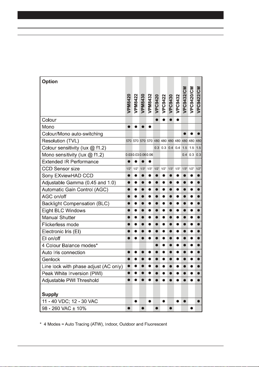
These instructions cover 3X series cameras. Read all of these instructions. Use them to install
your camera and have them available for its lifetime. If you have any problems, contact your
agent. Note that not all cameras have all of the features described in this manual. Refer to the
table below for the features of individual cameras. All 3X series cameras are fitted with a Direct
Drive (DD) lens connector, have adjustable back focus and accept C and CS lenses.
Page 2

Installation Instructions 3X Series Cameras
PRODUCT SAFETY
Installation and servicing is only to be carried out by suitably qualified and
experienced personnel.
Mains cameras contain hazardous voltages
Do not remove covers as there is a risk of injury or death by electric shock.
Cameras connected to mains supplies must be earthed.
Only power low voltage cameras from a class 2 isolated power supply.
The 3X series camera range is designed for use in general purpose CCTV applications and has
no other purpose. Only operate your camera between the temperatures of -10
O
C and +50OC.
Do not operate your camera outside its specified power supply range. 3X series cameras must
only be used in clean, dry, dust-free environments unless housed in a suitable protective
housing to IP65 or better.
ELECTROMAGNETIC COMPATIBILITY (EMC)
This is a class A product. In a domestic environment this product may cause radio
interference in which case the user may be required to take adequate measures.
This product is intended solely for use in general CCTV applications.
The product must be installed and maintained in accordance with good installation practice to
enable the product to function as intended and to prevent problems.
MANUFACTURERS DECLARATION OF CONFORMANCE
The manufacturer declares that the equipment supplied with this manual is compliant with the
essential protection requirements of the EMC directive 89/336 and the Low Voltage Directive
LVD 73/23 EEC. Conforming to the requirements of standards EN 55022 for emissions, IEC801
parts 2, 3 and 4 for immunity and EN 60950 for Electrical Equipment safety.
Page 3

3X Series Cameras Installation Instructions
CAUTIONS
In order to avoid damaging your camera, note the following points.
1) The camera has threaded mounting points on the top and bottom of the case.
Only use a standard, photographic mounting bolt with a 1/4-20 UNC thread.
2) Before fitting the lens, make sure that its back will not touch the CCD sensor or
associated components when screwed fully home.
3) Do not touch the image surface of the sensor. If the sensor is accidentally
touched, only clean it using isopropanol.
4) Do not expose the sensor to direct sunlight as this may impair the performance
of the camera.
POWER SUPPLY
3X series cameras are available in AC mains and AC and DC low voltage types. The voltage
required to operate the camera is clearly marked on the rear panel of the camera.
The green POWER LED on the rear panel indicates that power is connected. Only power low
voltage cameras from a class 2 isolated power supply. The power consumption of a 3X
series camera is less than 5 Watts.
Mains power supply
Cameras that are intended to operate directly from the mains supply are fitted with a nondetachable power supply cord. The voltage of operation is clearly marked on the rear panel of
the camera. Generally this is 98 - 260V AC at 50Hz. REFER TO THE WIRING INSTRUCTION
LABEL ATTACHED TO THE SUPPLY CORD and terminate the cord with the appropriate mains
plug fitted with a 3A fuse. MAINS CAMERAS MUST BE CONNECTED TO A PROTECTIVE
EARTH. Ensure that a secure means of isolation from the mains is provided for the camera in
accordance with the national wiring regulations of the country of installation.
Auto-switching power supply
Cameras fitted with an automatic selecting power supply operate between 11-40V DC and
12-30V AC. Connections and polarity are indicated above the screw terminals on the rear
panel. The power supply must be a class 2 isolated type.
VIDEO CONNECTIONS
To obtain a video output, connect a video coaxial cable terminated with a 75W BNC connector
to the BNC socket marked VIDEO OUT on the rear of the camera.
On selected cameras, a means of external synchronisation may be provided - see table 1 for
details. For external synchronisation, connect a video coaxial cable terminated with a 75W B NC
connector to the socket marked GENLOCK on the rear of the camera. The GENLOCK facility
synchronises to either a 1V peak-to-peak video signal or a standard sync plus blanking signal.
A signal connected to the GENLOCK input automatically overrides all other synchronisation
settings.
On colour cameras, the genlock facility locks the lines and not the subcarriers together.
Page 4
Installation Instructions 3X Series Cameras
S
T
S
FUNCTION SWITCHES
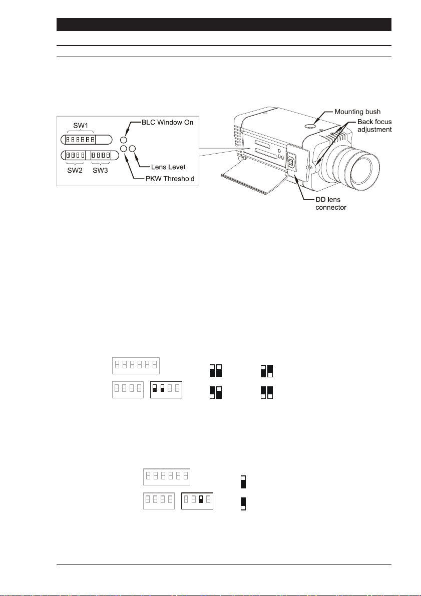
On the side of the camera is a hinged flap. The hinged flap covers a lens level potentiometer, the
Peak White Inversion threshold potentiometer, the BLC window activation button and three
banks of function switches.
Figure 1
Switch Naming Conventions
The DIP switches located under the hinged flap are in three banks SW1, SW2 and SW3.
Throughout this manual, switches are referenced in the following manner: SW1-3 which
corresponds to switch number 3 of switch bank 1.
Colour Balance
There are four colour balance modes selected by dip switches SW3-1 and SW3-2. For the
majority of applications the Auto setting will provide excellent colour rendition and is the default
setting. For applications where the illumination is predominantly daylight, the Outdoor setting
may provide improved colour rendition over Auto. Where a mixture of illuminations such as
tungsten, fluorescent and daylight exist, the Indoor setting may provide the best colour
rendition. Where fluorescent lighting is predominant use the Fluorescent setting.
W1
1
2
3
4
56
1122
AUTO
FLUORESCEN
1
2
33
44
SW2
1
SW3
2
INDOOR
OUTDOOR
Gamma
There are two different levels of Gamma selected by dip switch SW3-3. Choose between
NORM (Normal = 0.45) to provide increased visibility in dark areas of the scene, or LIN (Linear
= 1.0). The default setting is NORM.
W1
1
2
3
4
56
11
22
3
44
SW2
SW3
3
3
NORM (0.45)
LIN (1.0)
Page 5
3X Series Cameras Installation Instructions
S
F
S
J
S
S
0
FUNCTION SWITCHES
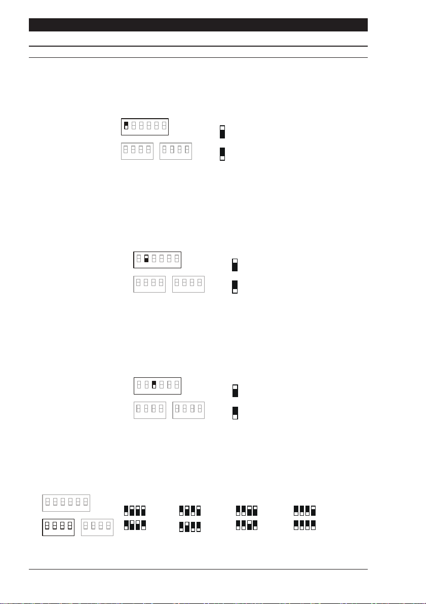
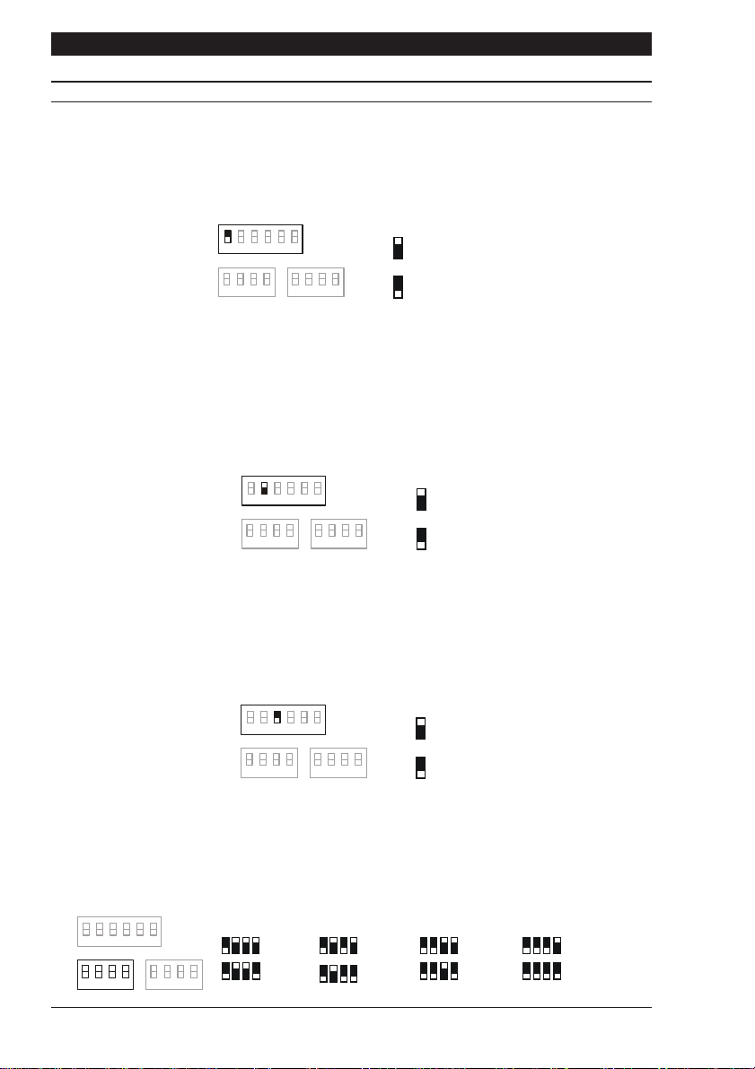
AGC (Automatic Gain Control)
The Automatic Gain Control feature can improve picture quality when the level of illumination is
low. Select ON or OFF using dip switch SW1-1. For most applications, the AGC feature should
be ON and is therefore the default setting.
W1
1
2
3
4
56
1
AGC OF
11
22
33
44
SW2 SW3
AGC ON
LL-PH (Line Lock, Phase Adjust)
The Line Lock, Phase Adjust feature is selected by dip switch SW1-2. Choose FIX (fixed) or
ADJ (adjustable). Both settings are line-locked however, the ADJ setting allows ±120
O
phase
adjustment via the potentiometer located on the rear of the camera. The ADJ mode should be
used when cameras are connected to different mains supply phases (R, Y, B). Default setting
is FIX.
W1
1
2
3
4
56
11
22
33
44
SW2 SW3
2
FIX
AD
SYNC (Synchronisation)
The Synchronisation feature is selected using dip switch SW1-3. Choose L/L (Line-Lock) or
INT (internal). L/L locks the frame rate to the mains so that cameras are triggered at the same
point on the mains supply AC cycle. INT locks the frame rate to the internal oscillator of the
camera. The default setting is L/L.
W1
1
2
3
4
56
11
22
33
44
SW2 SW3
3
INT
L/L
Shutter speed switches
Shutter speeds are selected with dip switches SW2-1, SW2-2, SW2-3 and SW2-4. Dip switch
SW2-1 must be down to enable manual shutter speed selection. For EI, BLC and Flickerless
functions, switch SW2-1 must be up.
W1
1
2341
1/4,0001/1,0001/2501/50
1/10,00
SW2
1
2
3
4
56
1
1
2
1
3
2
4
SW3
234
3
4
1/100
1
234
1/500
234
1/2,000
Page 6
Installation Instructions 3X Series Cameras
S
F
S
F
44444
4
66666
6
55555
5
FGHBC
D
FUNCTION SWITCHES
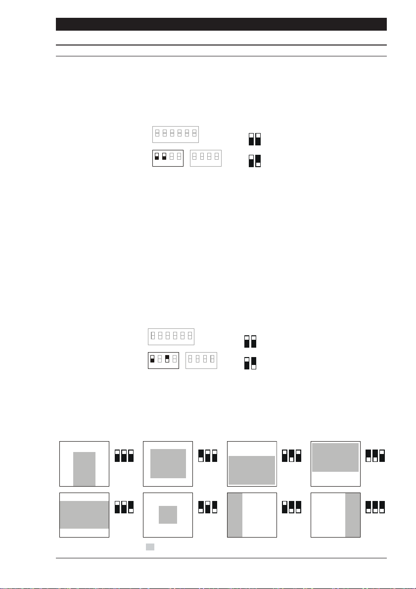
EI (Electronic Iris)
The EI (Electronic Iris) feature compensates for excessive light level by automatically adjusting
shutter speed. Selecting Electronic Iris disables manual shutter speed selection. The Electronic
Iris setting must not be used when the camera is set to Flickerless mode. The default setting is
Electronic Iris ON.
W1
2
3
4
56
1
12
EI ON
1
SW2
2
1
33
2
44
SW3
EI OF
BLC (Back Light Compensation)
The backlight compensation feature can be used to eliminate the effect of an area of strong
background lighting in a scene. If a strong background light such as a window exists in a
scene, the camera will try to compensate for it by reducing the overall exposure. This would
mean that the areas surrounding the window would become too dark.
By using the backlight compensation feature, it is possible to select areas of the scene which
may be used to control the exposure. Typically, the object of interest lies in the centre of the
scene and this is the area normally used to calculate the exposure. The edges, where strong
backlighting is likely to be, are ignored.
The BLC feature is switched ON or OFF using switch SW2-1 and SW2-3. Switch SW2-1 must
be up. Default is OFF. BLC will only function with a manual iris lens when the Electronic Iris
feature is switched on. For direct drive and auto iris lenses, BLC will still function even though
the Electronic Iris feature is switched off.
W1
1
2
3
4
56
1
22
SW2
1
3
44
SW3
3
13
BLC ON
BLC OF
To facilitate backlight compensation, eight pre-defined windows are provided. To select a
window, first, press the BLC window activation switch (see figure 1). This will superimpose
the currently selected window over the video output on the monitor. Use the three dip switches
SW1-4, SW1-5 and SW1-6 to select one of the pre-defined windows according to the diagram
below.
4
6
5
A
.
4
6
5
E
= area used to calculate camera exposure
Page 7

3X Series Cameras Installation Instructions
S
F
S
F
FUNCTION SWITCHES
The overlay window will automatically disappear 5 seconds after the last dip switch setting is
made. Any parts of the scene that are not covered by the BLC window will be ignored when
determining the overall scene exposure.
Back Light Compensation feature - Example 1.
People entering a shop through a brightly lit doorway are to be monitored. Without backlight
compensation, a person entering the shop would be seen in silhouette because the relatively
bright background would cause the camera to reduce its exposure.
By using the backlight compensation feature, it is possible to select a window around the area
of interest, i.e. the doorway. Choosing window A, will ensure that the camera exposure
system only uses the central area of the scene to calculate the scene exposure. Therefore a
person entering the shop will be clearly displayed.
Back Light Compensation feature - Example 2.
The camera is required to observe a typical street scene. The sky above the buildings in the
street is very bright causing the cameras exposure system to overcompensate. Using the
backlight compensation feature to select window C ensures that the relative brightness of the
sky in the scene doesnt adversely affect the exposure. The buildings and street will be
correctly exposed.
Flickerless
The Flickerless setting can reduce the flicker caused by certain lighting conditions. Choose
between ON or OFF. The default setting is OFF. Switch SW2-1 must be up. Note that the
Electronic Iris setting must be off for correct operation of the Flickerless function.
W1
2
3
4
56
1
1
22
SW2
1
33
4
SW3
4
14
FLICKERLESS ON
FLICKERLESS OF
Peak White Inversion (PKW)
Excessively bright or peak white areas in a scene can cause auto-iris lenses (Direct Drive and
Video Drive types) to react and close down thereby losing the detail in darker areas of the
scene. The Peak White Inversion feature is designed to overcome this. It allows you to render
any part of the scene over a certain brightness threshold as black.
A typical usage of this may occur in a highway surveillance role. Car headlamps would
normally cause an auto-iris lens to close. By using peak white inversion to render the headlamps
as black, the lens will not react to them and therefore correctly expose the rest of the scene.
W1
1
2
3
4
56
11
22
33
4
SW2
SW3
4
4
PKW ON
PKW OF
Page 8
Installation Instructions 3X Series Cameras
+
3 = Drive +
4 = Drive -
s
FUNCTION SWITCHES
Select PKW ON or OFF using dip switch SW3-4. The Peak White Inversion threshold potentiometer
(see figure 1), allows you to set the level above which all video is set to black. The default
setting for the camera is PKW OFF.
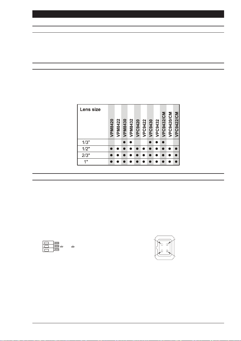
LENS SELECTION
Suitable lens types are C and CS mount in fixed iris, manual iris, auto iris or direct drive versions.
Sizes are shown below. Cameras are factory set for CS mount lenses. If using a C mount lens,
rotate either of the back focus screws approximately 30 turns anticlockwise before fitting the
lens.
LENS CONNECTION
Fixed and Manual iris lenses (for indoor use only) require no wiring connections.
Auto Iris Lenses
Connections for auto-iris lenses are located on the rear of the camera. Connect auto-iris lenses
to the 3 terminal connector according to the diagram below.
Direct Drive
Connect DD lenses to the female 4 pin socket on the side of the camera. If the lens does not
have a DD plug fitted then wire the lens to a suitable plug in accordance with the diagram below.
= Lens positive supply
+
+
= Lens ground
V
= Video drive signal
V
1
3
1 = Damp 2 = Damp
2
4
DD Lens ConnectorAuto-Iris Lens Connection
Page 9

3X Series Cameras Installation Instructions
LENS SETUP PROCEDURES
For manual or fixed iris lenses set the EI switch and AGC switch to ON.
Auto Iris lenses
Switch the EI and AGC off. Refer to the lens instructions and adjust the lens for the optimum
picture (video output level of 1V peak-to-peak). Switch the AGC on.
Direct Drive lenses
Where fitted, switch the EI and AGC off. Use an appropriate screwdriver to turn the lens level
potentiometer (under the hinged flap) fully clockwise. Next, slowly adjust the potentiometer
anticlockwise until the optimum picture is obtained (video output level of 1V peak-to-peak).
Switch the AGC on.
FOCUS ADJUSTMENT
The back focus adjustment screws are located on the top and side of the case and should be
adjusted using an appropriate screwdriver. If possible, always use the top screw to adjust the
back focus mechanism.
Turn the adjuster screw clockwise or anticlockwise to obtain focus. When the focus is sharp,
turn the back focus adjustment screw 2 or 3 turns anticlockwise. The picture will lose sharpness.
Turn the back focus screw clockwise until focus is once again obtained. If you have turned the
back focus screw clockwise past the point of best focus, repeat the procedure. The last turn
of the back focus adjustment screw must always be in a clockwise direction. Do not
over turn the back focus mechanism.
Fixed Lenses
Set the lens focus to infinity and view an image greater than two metres away. Focus the image
using the back focus screw. Set the lens focus as required.
Manual Iris Lenses
Open the iris fully and set the lens focus to infinity. View an image greater than two metres
away. Focus the image using the back focus screw. Set the lens focus and iris as required.
Auto Iris and Direct Drive Lenses
Fully open the iris by covering the lens with a suitable neutral density (ND) filter. Set the lens
focus to infinity. View an image greater than two metres away. Focus the image using the back
focus screw. Remove the ND filter and set the lens focus as required.
Zoom Lenses
Set the lens focus to infinity and fully open the iris by covering the lens with a suitable neutral
density (ND) filter. Zoom out to the widest field of vision and view a distant object. Adjust the
back focus screw until the object is in focus. Next, zoom fully in and adjust the lenses focus
until the object is again focused. Repeat these steps until the full zoom range may be viewed
with the minimum loss of focus.
Page 10
Installation Instructions 3X Series Cameras
SYNCHRONISATION
Cameras that operate from AC supplies are line-locked for a supply frequency of 50Hz. If the
supply frequency is unstable, then disable the line lock by setting the SYNC switch to INT.
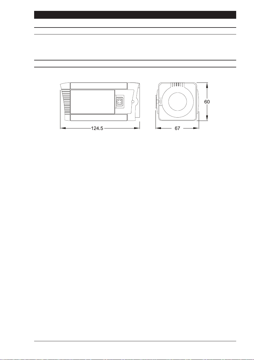
DIMENSIONS
Page 11

Caméras série 3X Notice dinstallation
Page 12

Caméras série 3X
Notice dinstallation
Caméras série 3X Notice dinstallation
INTRODUCTION
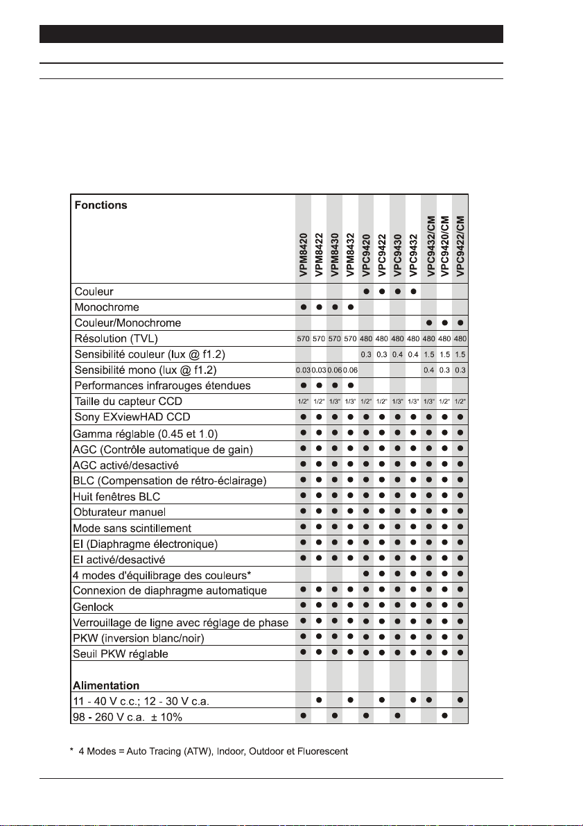
Cette notice concerne les caméras série 3X. Veuillez-la lire intégralement. Elle vous aidera à
installer votre caméra et restera à votre disposition pendant toute sa durée utile. En cas de
problème, prenez contact avec votre fournisseur. À noter que les caméras ne disposent pas
toutes des caractéristiques décrites dans cette notice. Pour connaître les caractéristiques des
caméras individuelles, reportez-vous au tableau ci-dessous. Toutes les caméras de la série 3X
sont équipées dun connecteur dobjectif à entraînement direct et dune mise au point réglable;
elles acceptent toutes les objectifs C et CS.
Page 14

Notice dinstallation Caméras série 3X
T
ON
SÉCURITÉ DU PRODUIT
IMPORTAN
Linstallation et la maintenance doivent uniquement être effectuées par un
technicien qualifié et expérimenté.
Des tensions dangereuses sont présentes dans les caméras secteur.
Ne pas déposer les couvercles pour éviter tout risque daccident corporel ou
fatal par électrocution.
Les caméras connectées au secteur doivent être mises à la terre.
Seules les caméras basse tension doivent être alimentées par une alimentation
isolée de classe 2.
La gamme de caméras série 3X a été conçue pour les applications de caméras en circuit fermé
à usage général et nassure aucun autre objectif. Votre caméra doit opérer à une température
comprise entre -10°C et +50°C. Elle ne doit pas opérer hors de la plage dalimentation spécifiée.
Les caméras de la série 3X doivent être utilisées dans un environnement propre, sec et non
poussiéreux, sauf si elles sont installées dans une armoire de protection conforme à la norme
IP65 ou supérieure.
COMPATIBILITÉ ÉLECTROMAGNÉTIQUE
ATTENTI
Il sagit dun produit de classe A. Dans un environnement domestique, ce produit
est susceptible de provoquer des interférences radio, auquel cas lutilisateur
devra éventuellement prendre des mesures appropriées.
Ce produit se destine exclusivement aux applications de caméras en circuit fermé.
Son installation et sa maintenance doivent être réalisées conformément aux pratiques appropriées
pour lui permettre de fonctionner de la manière prévue et éviter lapparition de problèmes.
DÉCLARATION DE CONFORMITÉ DU CONSTRUCTEUR
Le constructeur déclare que léquipement fourni avec cette notice se conforme aux
caractéristiques essentielles de protection de la directive 89/336 sur la compatibilité
électromagnétique et de la directive LVD 73/23 EEC sur les basses tensions. Léquipement est
conforme aux caractéristiques des normes EN 55022 sur les émissions, IEC801 paragraphes
2, 3 et 4 sur limmunité et EN 60950 sur la sécurité des équipements électriques.
Page 15

Caméras série 3X Notice dinstallation
N
PRÉCAUTIONS
ATTENTIO
Pour éviter dendommager votre caméra, veuillez tenir compte des points suivants:
1) La caméra comporte des points de montage filetés au-dessus et au-dessous
de son boîtier. Utilisez uniquement un boulon de montage photographique
standard à filetage 1/4-20 UNC.
2) Avant dinstaller lobjectif, assurez-vous que sa partie arrière ne touche pas le
capteur à couplage de charge (CCD) ni les composants associés une fois
totalement vissé en position.
3) Ne touchez pas à la surface dimagerie du capteur. En cas de contact accidentel
avec le capteur, nettoyez-le uniquement avec de lisopropanol.
4) Nexposez pas directement le capteur au soleil, sous peine daffecter les
performances de la caméra.
ALIMENTATION
Les caméras de la série 3X sont disponibles en versions secteur c.a. et basse tension c.a. et
c.c. La tension opérationnelle de la caméra est clairement indiquée sur son panneau
arrière. Le voyant dalimentation vert à larrière indique que la caméra est sous tension. Seules
les caméras basse tension doivent être alimentées par une alimentation isolée de classe 2. La
consommation électrique dune caméra série 3X est inférieure à 5 watts.
Alimentation secteur
Les caméras prévues pour opérer directement sur le secteur sont équipées dun cordon
dalimentation ne pouvant pas être détaché. La tension opérationnelle est clairement indiquée
sur le panneau arrière de la caméra. Il sagit généralement de 98 - 260V c.a. à 50Hz. REPORTEZVOUS À LÉTIQUETTE COMPORTANT LES INSTRUCTIONS DE CÂBLAGE SUR LE CORDON
DALIMENTATION et munissez le cordon dune prise secteur appropriée équipée dun fusible 3
A. LES CAMÉRAS SECTEUR DOIVENT ÊTRE CONNECTÉES À UNE TERRE DE PROTECTION.
Assurez-vous quil existe un moyen sécurisé disoler la caméra du secteur conformément aux
réglementations nationales de câblage dans le pays dinstallation.
Alimentation à commutation automatique
Les caméras équipées dune alimentation à sélection automatique opèrent sur une tension de
11-40 V c.c. et de 12-30 V c.a. Les connexions et la polarité sont indiquées au-dessus des
bornes à vis sur le panneau arrière. Il doit sagir dune alimentation isolée de classe 2.
CONNEXIONS VIDÉO
Pour obtenir une sortie vidéo, branchez un câble vidéo coaxial muni dun connecteur BNC 75W
sur la prise BNC annotée VIDEO OUT à larrière de la caméra.
Certaines caméras bénéficient dun moyen de synchronisation externe. Pour plus de détails,
reportez-vous au tableau 1. Pour obtenir une synchronisation externe, branchez un câble
vidéo coaxial muni dun connecteur BNC 75W sur la prise annotée GENLOCK à larrière de la
caméra. La fonction GENLOCK se synchronise sur un signal vidéo 1 V crête à crête ou un
signal vidéo standard plus suppression. Un signal connecté à lentrée GENLOCK remplace
automatiquement tout autre réglage de synchronisation.
La fonctionnalité GENLOCK verrouille les lignes entre elles, plutôt que les sous-porteuses
(caméras couleur uniquement).
Page 16
Notice dinstallation Caméras série 3X
S
T
S
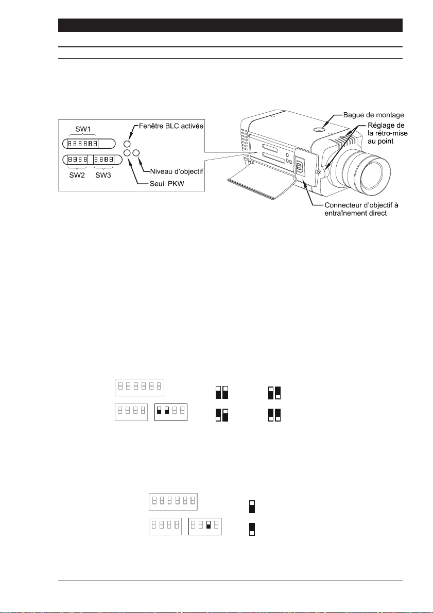
COMMUTATEURS DE FONCTION
Sur le côté de la caméra figure un cache à charnières. Ce cache dissimule le potentiomètre de
niveau dobjectif, le potentiomètre dinversion blanc/noir (PKW), le bouton dactivation de fenêtre
BLC et trois rangées de commutateurs de fonction.
Figure 1
Conventions de dénomination des commutateurs
Les commutateurs DIP situés au-dessous du cache à charnières sont répartis en trois rangées
SW1, SW2 et SW3. Dans la suite de ce manuel, ils sont désignés comme suit: SW1-3 correspond
au commutateur numéro 3 de la première rangée de commutateurs.
Équilibrage des couleurs
Il existe quatre modes déquilibrage des couleurs sélectionnés par les commutateurs DIP SW31 et SW3-2. Dans la majorité des applications, le réglage Auto fournit un excellent rendu de
couleur et constitue donc le réglage par défaut. Dans les applications où léclairage est
essentiellement la lumière du jour, le réglage Outdoor (extérieur) pourra améliorer le rendu de
couleur par rapport au réglage Auto. Avec un éclairage combiné (tungstène, fluorescent et
lumière du jour par exemple), le réglage Indoor (intérieur) pourra fournir le meilleur rendu de
couleur. Si léclairage est essentiellement fluorescent, utilisez le réglage Fluorescent.
W1
1
2
3
4
56
1122
AUTO
FLUORESCEN
1
2
33
44
SW2
1
SW3
2
INDOOR
OUTDOOR
Gamma
Il existe deux niveaux gamma différents sélectionnés par le commutateur DIP SW3-3. Vous
avez le choix entre NORM (Normale = 0,45) pour obtenir une meilleure visibilité dans les zones
sombres ou LIN (Linéaire = 1,0). Le réglage par défaut est NORM.
W1
1
2
3
4
56
11
22
3
44
SW2
SW3
3
3
NORM (0.45)
LIN (1.0)
Page 17
Caméras série 3X Notice dinstallation
S
F
S
J
S
T
S
0
COMMUTATEURS DE FONCTION
AGC (Automatic Gain Control - contrôle automatique du gain)
Le contrôle automatique de gain AGC permet daméliorer la qualité de limage en présence dun
niveau déclairage insuffisant. Vous pouvez lactiver (ON) ou le désactiver (OFF) au moyen du
commutateur DIP SW1-1. Dans la majorité des applications, la fonction AGC doit être activée
(ON) et constitue donc le réglage par défaut.
W1
1
2
3
4
56
1
AGC OF
11
22
33
44
SW2 SW3
AGC ON
LL-PH (Line Lock, Phase Adjust - verrouillage de ligne, réglage de phase)
La fonction de verrouillage de ligne et de réglage de phase (LL-PH) est sélectionnée par le
commutateur DIP SW1-2. Vous avez le choix entre FIX (fixe) et ADJ (réglable). Les deux
réglages assurent un verrouillage de ligne; toutefois, le réglage ADJ permet un ajustement de
phase de ±120° via le potentiomètre situé à larrière de la caméra. Le mode ADJ doit être utilisé
lorsque les caméras sont connectées à différentes phases dalimentation secteur (R, Y, B). La
valeur par défaut est FIX.
W1
1
2
3
4
56
11
22
33
44
SW2 SW3
2
FIX
AD
SYNC (synchronisation)
La fonction de synchronisation (SYNC) est réglée au moyen du commutateur DIP SW1-3. Vous
avez le choix entre L/L (verrouillage de ligne) et INT (interne). L/L verrouille la vitesse de trame
sur le secteur pour déclencher les caméras au même point dans le cycle dalimentation secteur
c.a. Le réglage INT verrouille la vitesse de trame sur loscillateur interne de la caméra. La valeur
par défaut est L/L.
W1
1
2
3
4
56
11
22
33
44
SW2 SW3
3
IN
L/L
Commutateurs de vitesse dobturateur
La vitesse dobturateur est sélectionnée au moyen des commutateurs DIP SW2-1, SW2-2 et
SW2-3. Le commutateur DIP SW2-1 doit être en position inférieure pour permettre la sélection
manuelle de vitesse dobturateur. Pour les fonctions EI, BLC et sans scintillement, le commutateur
SW2-1 doit être en position supérieure.
W1
1
1
1
SW2
1
2
3
4
56
2
1
3
2
SW3
3
4
234
4
1/100
1
234
1/500
234
1/2,000
2341
Page 18
1/4,0001/1,0001/2501/50
1/10,00
 Loading...