

Vista VPM8130, VPM8120, VPM8030, VPC9132-CM, VPC9132 User Manual 2
...
VPM8030
VPM8032
VPM8130
VPM8132
VPM8120
VPM8122
VPC9030
VPC9032
VPC9130
VPC9132
VPC9032/CM
VPC9130/CM
VPC9132/CM
Series 3 CCD Cameras
Installation Instructions
Installation Instructions
Instructions d’installation
Installationanweisungen
Installatie-instructies
Istruzioni di ins tallazione
GB
F
D
NL
2112131
I
41
Series 3 Cameras Installation Instructions
INTRODUCTION
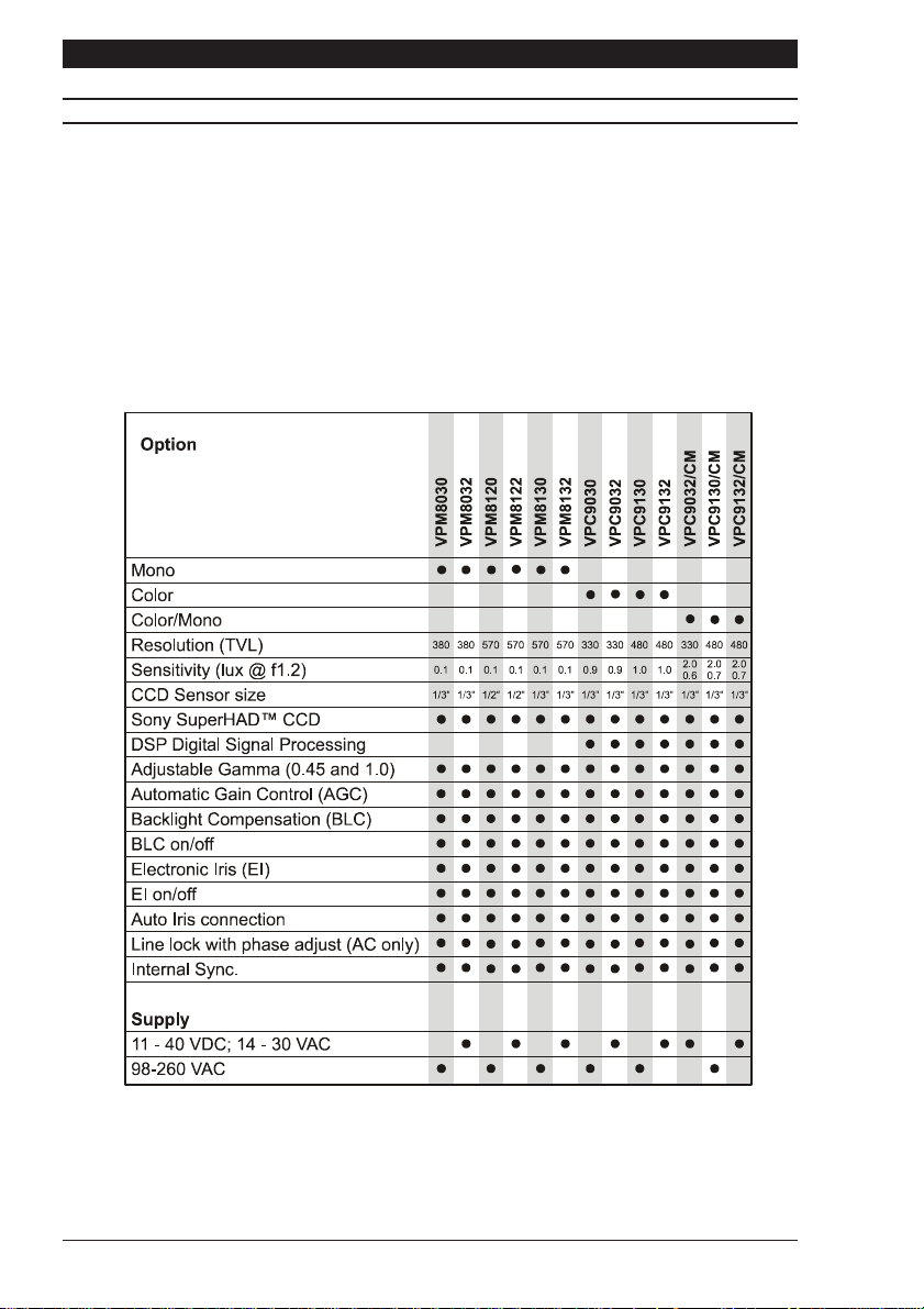
Read all of these instructions. Use them to install your camera and have them available for
its lifetime. If you have any problems, contact your agent. Note that not all cameras have all
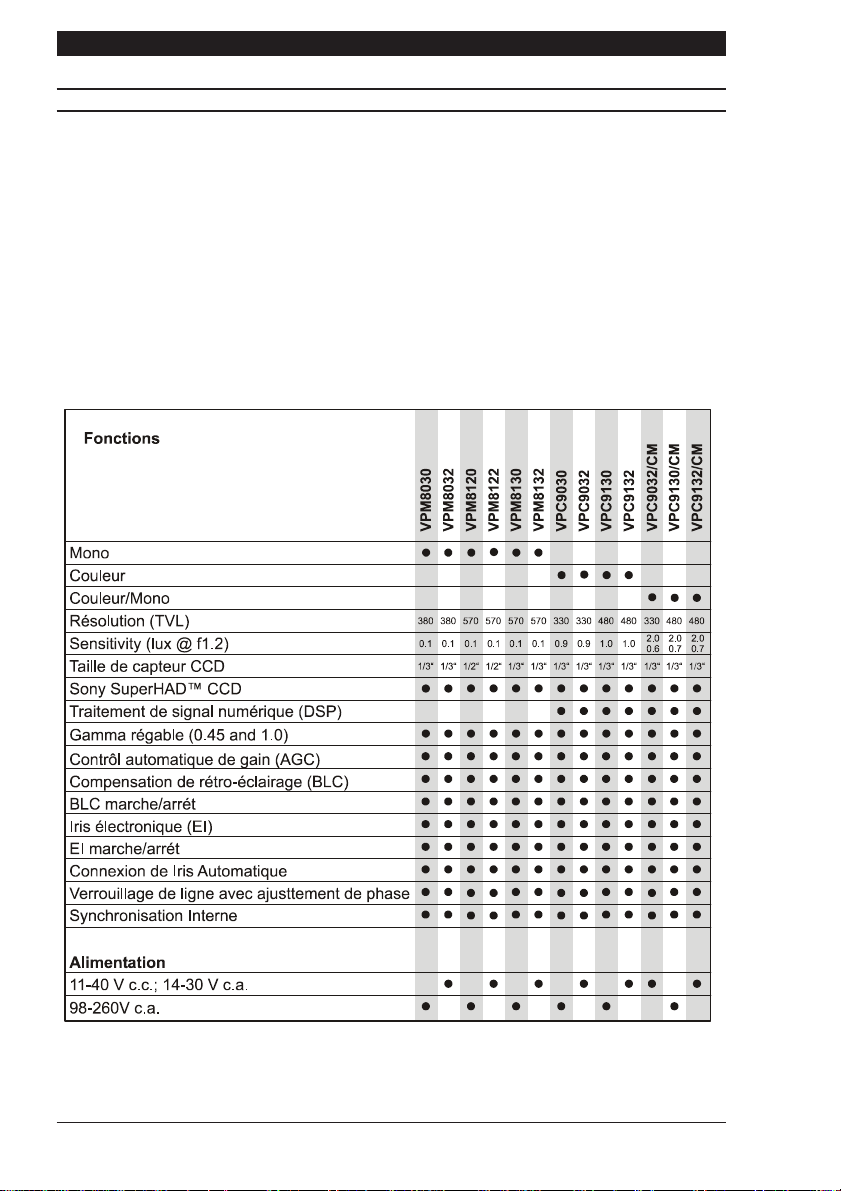
of the features described in this manual. Refer to the table below for the features of individual
cameras. All cameras are fitted with a Direct Drive (DD) lens connector, an Auto Iris (AI)
connector, have adjustable back focus and accept C and CS lenses.
VPC.../CM cameras are designed to give a good image over a broad range of lighting
conditions. To achieve this, the cameras operate in colour mode where the scene illumination
is bright and automatically switch to monochrome where the scene illumination is low.
Typically, the switchover occurs at approximately 2.0 lux.
TABLE 1
Note: NTSC and EIA camera models have suffixes /N and /E respectively. These variants
are also covered by Table 1
Page 2

Installation Instructions Series 3 Cameras
PRODUCT SAFETY
Installation and servicing is only to be carried out by suitably qualified and
experienced personnel.
Mains cameras contain hazardous voltages
Do not remove covers as there is a risk of injury or death by electric shock.
Cameras connected to mains supplies must be earthed.
Only power low voltage cameras from a class 2 isolated power supply.
This camera range is designed for use in general purpose CCTV applications and has no
other purpose. Only operate your camera between the temperatures of -10
O
C and +50OC.
Do not operate your camera outside its specified power supply range. Cameras must only
be used in clean, dry, dust-free environments unless housed in suitable protective housings
to IP65 or better.
ELECTROMAGNETIC COMPATIBILITY (EMC)
This is a class A product. In a domestic environment this product may cause radio
interference in which case the user may be required to take adequate measures.
This product is intended solely for use in general CCTV applications.
The product must be installed and maintained in accordance with good installation practice
to enable the product to function as intended and to prevent problems. Refer to your agent
for installation guidance.
MANUFACTURERS DECLARATION OF CONFORMANCE
The manufacturer declares that the equipment supplied with this manual is compliant with
the essential protection requirements of the EMC directive 89/336 and the Low Voltage
Directive LVD 73/23 EEC. Conforming to the requirements of standards EN 55022 for
emissions, IEC801 parts 2, 3 and 4 for immunity and EN 60950 for Electrical Equipment
safety.
Page 3

Series 3 Cameras Installation Instructions
CAUTIONS
In order to avoid damaging the camera note the following points.
1) The camera has threaded mounting points on the top and bottom of the case.
Only use a standard, photographic, mounting-bolt with a 1/4 BSW (20 UNC) thread.
2) Before fitting the lens make sure that its back will not touch the CCD sensor or
associated components when screwed fully home.
3) Do not touch the image-surface of the sensor. If the sensor is accidentally touched,
only clean it using ethyl alcohol.
4) Do not expose the sensor to direct sunlight as this may impair the performance of
the camera.
5) The weight of your camera is 0.5kg. (0.35kg. for VP.....2 versions)
6) Only use your camera in a clean, dust-free environment.
7) For outdoor use, an appropriate protective housing conforming to IP65 or UL50
or better must be used.
POWER SUPPLY
Cameras are available in AC mains and AC and DC low voltage types. The voltage required
to operate the camera is clearly marked on the rear panel of the camera. Only power
low voltage cameras from a class 2 isolated power supply. The power consumption of
a series 3 camera is less than 5 Watts.
Mains power supply
Cameras that are intended to operate directly from the mains supply are fitted with a nondetachable power supply cord. The voltage of operation is clearly marked on the rear panel
of the camera. Generally this is 98 to 260 VAC at 50 Hz for CCIR/PAL (110 VAC ±10% at
60 Hzfor EIA/NTSC). REFER TO THE WIRING INSTRUCTION LABEL ATTACHED TO
THE SUPPLY CORD and terminate the cord with the appropriate mains plug fitted with a
3A fuse. MAINS CAMERAS MUST BE CONNECTED TO A PROTECTIVE EARTH
GROUND. Ensure that a secure means of isolation from the mains is provided for the
camera in accordance with the national wiring regulations of the country of installation.
Auto-switching power supply
Cameras fitted with an automatic selecting power supply operate between 11-40 VDC and
14-30 VAC. Connections and polarity are indicated above the screw terminals on the rear
panel. The power supply must be a class 2 isolated type.
Page 4
Installation Instructions Series 3 Cameras
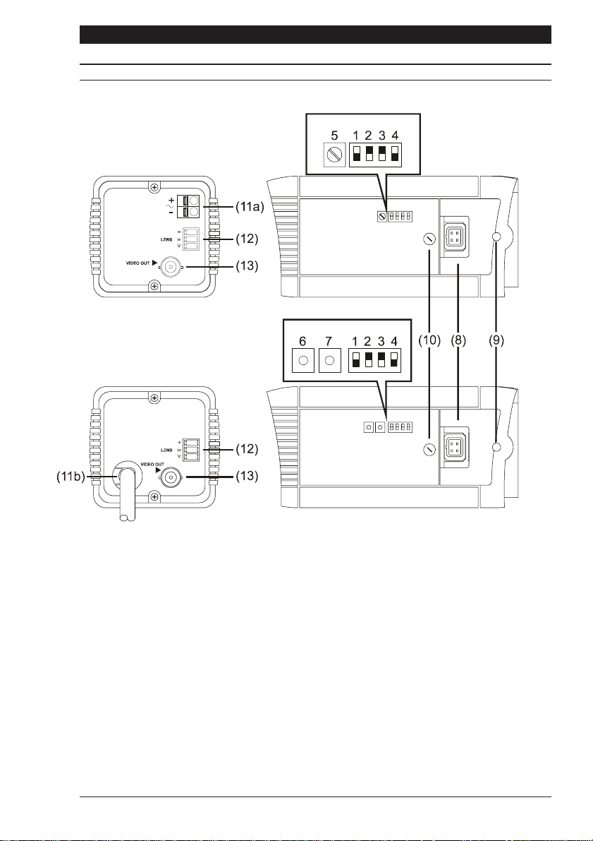
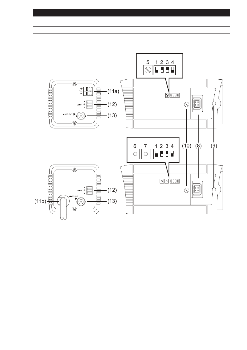
CONTROLS AND SWITCHES
On the side of the camera is a hinged flap. The hinged flap covers various adjustment
controls and function switches.
MONOCHROME
LOW VOLTAGE MODELS
COLOUR
230 VAC/ 110 VAC MODELS
Default switch positions shown (white represents switch position)
(1) Synchronisation Selection (LL/INT)
This switch is used to select the camera synchronisation mode. When the camera is
connected to an AC supply the Line-lock (LL) mode can be used. This locks the camera
frame rate to the mains frequency so that cameras in a system are triggered at the same
point on the mains AC cycle. Also see 5, 6 and 7 Line Lock Phase Adjustment.
(2) Backlight Compensation (BLC)
The BLC (Back Light Compensation) facility compensates for back-lit scenes by enhancing
objects in the centre of the scene which would previously have been in silhouette. Select
ON or OFF using the BLC switch. Default is OFF. BLC will only function with a manual iris
lens when the Electronic Iris facility is switched on. For direct drive and auto iris lenses,
BLC will still function even though the Electronic Iris facility is switched off.
(3) Gamma
Two different gamma correction options are available. Select Normal (0.45) to provide
increased visibility in dark areas of the scene, or Linear (1.0). The default setting is Normal.
Page 5

Series 3 Cameras Installation Instructions
+
CONTROLS AND SWITCHES
(4) Electronic Iris (EI)
The Electronic Iris (EI) compensates for excessive light level by automatically adjusting the
shutter speed. The electronic iris should be ON when using fixed or manual iris lenses.
When using Auto Iris (AI) lenses of either the video drive or DC drive types the EI must be
OFF. Also see (10) Electronic Iris and DC Lens Level Adjustment Potentiometer.
(5) Line Lock Phase Adjust Potentiometer
When the camera is in line-lock mode it is possible to adjust the point on the AC cycle at
which the camera triggers. This facility is provided so that cameras that are connected to
different mains phases may still be synchronised.
The line lock phase adjustment potentiometer allows the line lock phase trigger point to be
adjusted by ±120
O
. Rotating the potentiometer clockwise advances the trigger point and
turning it anticlockwise retards the trigger point. The factory default setting is the zero
crossing point. If all cameras in a system are on the same mains phase then no line lock
phase adjustment should be made.
(6 and 7) Line Lock Phase Adjust Buttons (+ Advance; - Retard)
When the camera is in line-lock mode it is possible to adjust the point on the AC cycle at
which the camera triggers. This facility is provided so that cameras that are connected to
different mains phases may still be synchronised.
The line lock phase adjustment buttons allows the line lock phase trigger point to be adjusted
O
by ±120
. Pressing the advance button advances the trigger point and pressing the retard
button retards the trigger point. The factory default setting is the zero crossing point. If all
cameras in a system are on the same mains phase then no line lock phase adjustment
should be made.
(8) Direct Drive/DC Drive Lens Connector
This 4-pin connector supplies the power and DC control signal for use with DC drive Auto
Iris lenses. If the lens does not have a DD plug fitted then wire the lens to a suitable plug in
accordance with the diagram below:
1
3
1 = Damp 2 = Damp
3 = Drive +
2
4
4 = Drive -
DD Lens Connector
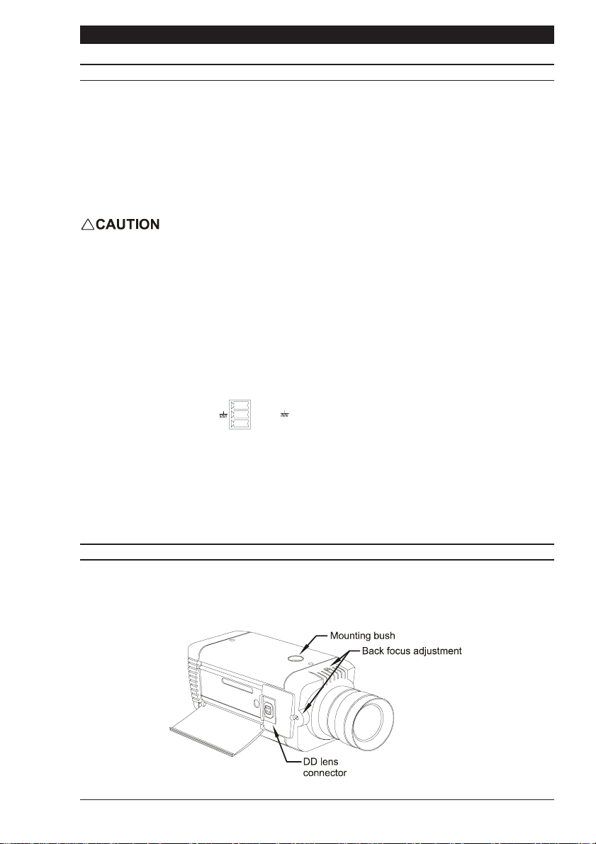
(9) Back Focus Adjustment screws
These two adjustment points located on the camera body top and side (top not shown), are
used to adjust the back focal length or picture focus. The range of adjustment allows both
C and CS mount lenses to be used without the need for a spacer ring. Refer to the section
on Focus Adjustment
(10) Electronic Iris and DC Lens Level Adjustment Potentiometer
If the camera is used with a direct drive (DD) lens this potentiometer varies the DC reference
voltage used to control the lens. The potentiometer has the effect of increasing or decreasing
the lens aperture. This potentiometer should be set to obtain a 1V pk-pk video output.
If a mono camera (VPM..) is used with a manual iris or fixed iris lens, and hence the
electronic iris is switched ON, this potentiometer controls the electronic
Page 6
Installation Instructions Series 3 Cameras
s
CONTROLS AND SWITCHES
iris level. The potentiometer is factory set to give a 1V pk-pk video output for a typical
scene. The level should not be adjusted unless absolutely necessary.
(11a) Supply Voltage Terminals
This terminal accepts 11-40 VDC or 14-30 VAC at 50Hz (CCIR/PAL) or 60Hz (EIA/NTSC)
power source. The terminals are the quick release type. To connect a cable press the
appropriate release lever and insert the end of cable fully home. Ensure that there is a
sufficient length of bare tinned wire to make contact with the connector. Also ensure that
the cable insulation is not too thick, preventing the cable from being properly inserted.
Only connect the camera to a class 2 power supply.
(11b) Supply Voltage Power Cord
The non-detachable power supply cord must be connected to a power supply of 98 to 260
VAC at 50Hz (CCIR/PAL); or 110 VAC ±10% at 60Hz (EIA/NTSC). CAMERAS MUST BE
CONNECTED TO A PROTECTIVE EARTH GROUND.
(12) Video Iris Lens Connector
This three way connector provides the power and video drive signal for use with video
drive Auto Iris lenses. The terminal block that mates with this connector is provided in the
packing kit. Connect the lens to the terminal block in accordance with the diagram below:
= Lens positive supply
+
V
+
= Lens ground
= Video drive signal
V
Auto Iris Lens Connection
(13) Video Output BNC Connector
To obtain a 1.0V [pk-pk] composite video signal, connect a video coaxial cable terminated
with a 75 Ohm BNC connector to the BNC socket marked VIDEO OUT.
CAMERA MOUNTING
Mounting points are provided on the top and bottom of the camera and are used to mount
the camera on a bracket or tripod. Only use standard, photographic 1/4 BSW (20 UNC)
mounting bolts.
Page 7
Series 3 Cameras Installation Instructions
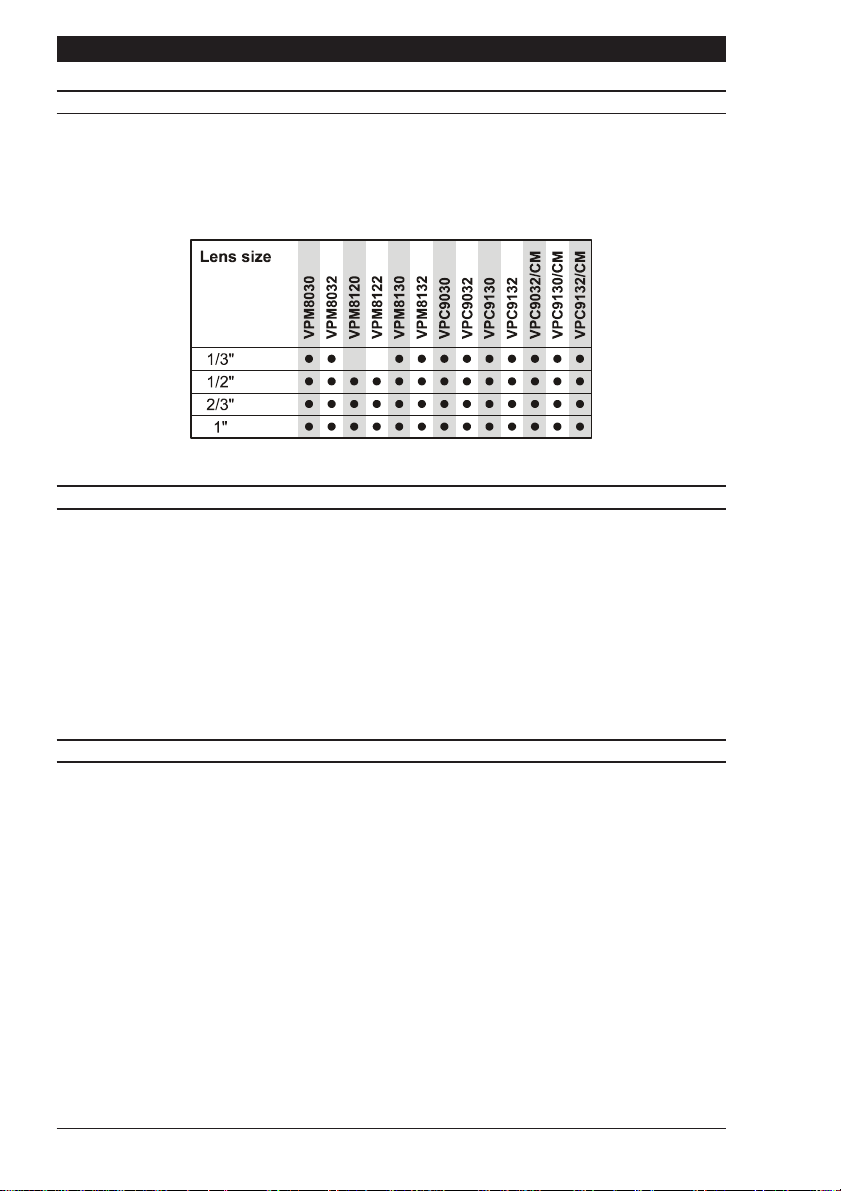
LENS SELECTION
Suitable lens types are C and CS mount in fixed iris, manual iris, auto iris or direct drive
versions. Sizes are shown below. Cameras are factory set for CS mount lenses. If using a
C mount lens, rotate either of the back focus screws approximately 30 turns anticlockwise
before fitting the lens.
LENS SETUP PROCEDURES
For manual or fixed iris lenses set the EI switch to ON.
Auto Iris lenses
Switch the EI off. Refer to the lens instructions and adjust the lens for the optimum picture
(video output level of 1V peak-to-peak).
Direct Drive lenses
Switch the EI off. Use an appropriate screwdriver to turn the lens level potentiometer (under
the hinged flap) fully clockwise then back off until the optimum picture is obtained (video
output level of 1V peak-to-peak).
FOCUS ADJUSTMENT
The back focus adjustment screws are located on the top and side of the case and should
be adjusted using an appropriate screwdriver. If possible, always use the top screw to
adjust the back focus mechanism.
Turn the adjuster screw clockwise or anticlockwise to obtain focus. When the focus is
sharp, turn the back focus adjustment screw 2 or 3 turns anticlockwise. The picture will
lose sharpness. Turn the back focus screw clockwise until focus is once again obtained. If
you have turned the back focus screw clockwise past the point of best focus, repeat the
procedure. The last turn of the back focus adjustment screw must always be in a
clockwise direction. Do not over turn the back focus mechanism.
Fixed Lenses
Set the lens focus to infinity and view an image greater than two metres away. Focus the
image using the back focus screw. Set the lens focus as required.
Manual Iris Lenses
Open the iris fully and set the lens focus to infinity. View an image greater than two metres
away. Focus the image using the back focus screw. Set the lens focus and iris as required.
Page 8
Installation Instructions Series 3 Cameras
FOCUS ADJUSTMENT
Auto-iris and Direct Drive Lenses
Fully open the iris by covering the lens with a suitable neutral density (ND) filter. Set the
lens focus to infinity. View an image greater than two metres away. Focus the image using
the back focus screw. Remove the ND filter and set the lens focus as required.
Zoom Lenses
Set the lens focus to infinity and fully open the iris by covering the lens with a suitable
neutral density (ND) filter. Zoom out to the widest field of vision and view a distant object.
Adjust the back focus screw until the object is in focus. Next, zoom fully in and adjust the
lens until the object is again focused. Repeat these steps until the full zoom range may be
viewed with the minimum loss of focus.
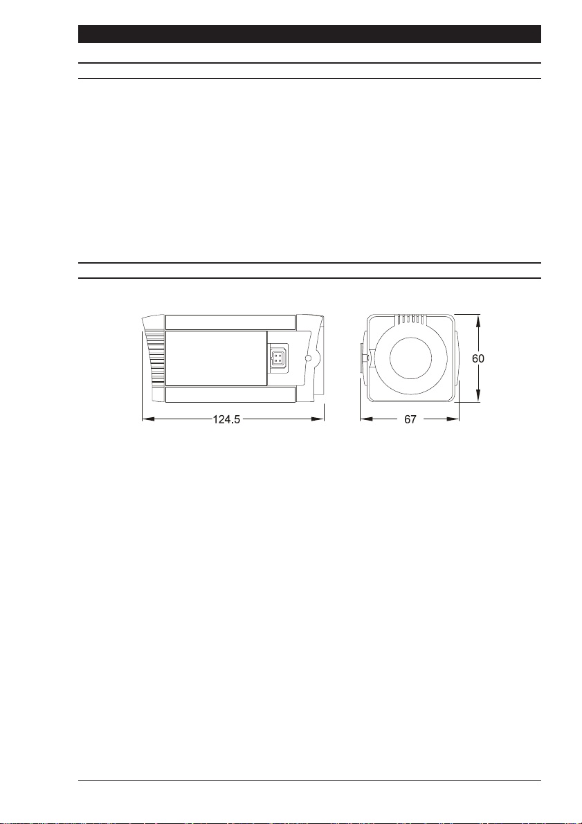
DIMENSIONS
Page 9

Series 3 Cameras Installation Instructions
Page 10

Série 3 Caméras
Instructions dinstallation
Série 3 Caméras Instructions dinstallation
INTRODUCTION
Veuillez-la lire intégralement. Elle vous aidera à installer votre caméra et restera à votre
disposition pendant toute sa durée utile. A noter que les caméras ne disposent pas toutes
des caractéristiques décrites dans cette notice. Pour connaître les caractéristiques des
caméras individuelles, reportez-vous au tableau ci-dessous. Toutes les caméras sont
équipées dun connecteur dobjectif à entraînement direct, dun connecteur de diaphragme
électronique et dune mise au point réglable; elles acceptent toutes les objectifs C et CS.
Les caméras à commutation couleur/monochrome (VPC.../CM) ont été conçues pour fournir
une image de qualité dans toute une variété de conditions déclairage. Pour y parvenir,
elles opèrent en mode couleur en présence dun éclairage vif et reviennent automatiquement
au monochrome lorsque léclairage de la scène saffaiblit. La commutation seffectue
généralement à 2 lux environ.
TABLEAU 1
Remarque: Les modèles de caméras NTSC et EIA ont respectivement les suffixes /N et
/E. Ces variantes sont également traitées au tableau 1
Page 12

Instructions dinstallation Série 3 Caméras
T
ON
SECURITE DU PRODUIT
IMPORTAN
Linstallation et la maintenance doivent uniquement être effectuées par un
technicien qualifié et expérimenté.
Des tensions dangereuses sont présentes dans les caméras secteur.
Ne pas déposer les couvercles pour éviter tout risque daccident corporel ou fatal
par électrocution.
Les caméras connectées au secteur doivent être mises à la terre.
Seules les caméras basse tension doivent être alimentées par une alimentation
isolée de classe 2.
Cette gamme de caméras a été conçue pour les applications de caméras en circuit fermé
à usage général et nassure aucun autre objectif. Votre caméra doit opérer à une température
comprise entre -10 et +50
spécifiée. Les caméras doivent être utilisées dans un environnement propre, sec et non
poussiéreux, sauf si elles sont installées dans une armoire de protection conforme à la
norme IP65 ou supérieure.
O
C. Elle ne doit pas opérer hors de la plage dalimentation
COMPATIBILITE ELECTROMAGNETIQUE
ATTENTI
Il sagit dun produit de classe A. Dans un environnement domestique, ce produit est
susceptible de provoquer des interférences radio, auquel cas lutilisateur devra
éventuellement prendre des mesures appropriées.
Ce produit se destine exclusivement aux applications de caméras en circuit fermé.
Son installation et sa maintenance doivent être réalisées conformément aux pratiques
appropriées pour lui permettre de fonctionner de la manière prévue et éviter lapparition de
problèmes. Pour plus de détails sur linstallation, prenez conseil auprès de votre revendeur.
DECLARATION DE CONFORMITE DU CONSTRUCTEUR
Le constructeur déclare que léquipement fourni avec cette notice se conforme aux
caractéristiques essentielles de protection de la directive 89/336 sur la compatibilité
électromagnétique et de la directive LVD 73/23 EEC sur les basses tensions. Léquipement
est conforme aux caractéristiques des normes EN 55022 sur les émissions, IEC801
paragraphes 2, 3 et 4 sur limmunité et EN 60950 sur la sécurité des équipements électriques.
Page 13

Série 3 Caméras Instructions dinstallation
N
PRECAUTIONS
ATTENTIO
Pour éviter dendommager la caméra, veuillez tenir compte des points suivants:
1) La caméra comporte des points de montage filetés au-dessus et au-dessous de
son boîtier. Utilisez uniquement un boulon de montage photographique standard
à filetage BSW 1/4 pouce (20 UNC).
2) Avant dinstaller lobjectif, assurez-vous que sa partie arrière ne touche pas le
capteur à couplage de charge (CCD) ni les composants associés une fois
totalement vissé en position.
3) Ne touchez pas à la surface dimagerie du capteur. En cas de contact accidentel
avec le capteur, nettoyez-le uniquement avec de lalcool éthylique.
4) Nexposez pas directement le capteur au soleil, sous peine daffecter les
performances de la caméra.
5) Votre caméra pèse 500g. (350g pour les versions VP....2)
6) La caméra ne doit être utilisée que dans un endroit propre et non poussiéreux.
7) Pour un usage en extérieur, vous devez utiliser un boîtier protecteur approprié
conforme ou supérieur à la norme IP65 ou UL50.
ALIMENTATION
Les caméras sont disponibles en versions secteur c.a. et basse tension c.a. et c.c. La
tension opérationnelle de la caméra est clairement indiquée sur son panneau arrière.
Seules les caméras basse tension doivent être alimentées par une alimentation isolée
de classe 2. La consommation électrique dune caméra série 3 est inférieure à 5 watts.
Alimentation secteur
Les caméras prévues pour opérer directement sur le secteur sont équipées dun cordon
dalimentation ne pouvant pas être détaché. La tension opérationnelle est clairement indiquée
sur le panneau arrière de la caméra. Il sagit généralement de 98-260 Vc.a. à 50 Hz pour
CCIR/PAL (110 V c.a. ±10% à 60 Hzpour EIA/NTSC). REPORTEZ-VOUS A LETIQUETTE
COMPORTANT LES INSTRUCTIONS DE CABLAGE SUR LE CORDON DALIMENTATION
et munissez le cordon dune prise secteur appropriée équipée dun fusible 3 A. LES
CAMERAS SECTEUR DOIVENT ETRE CONNECTEES A UNE TERRE DE PROTECTION.
Assurez-vous quil existe un moyen sécurisé disoler la caméra du secteur conformément
aux réglementations nationales de câblage dans le pays dinstallation.
Alimentation à commutation automatique
Les caméras équipées dune alimentation à sélection automatique opèrent sur une tension
de 11-40 V c.c. et de 14-30 V c.a. Les connexions et la polarité sont indiquées au-dessus
des bornes à vis sur le panneau arrière. Il doit sagir dune alimentation isolée de
classe 2.
Page 14
Instructions dinstallation Série 3 Caméras
COMMANDES ET COMMUTATEURS
Sur le côté de la caméra figure un cache à charnières. Le cache à charnières protège
différents commutateurs de fonctions et commandes de réglage.
MONO
MODÈLES BASSE TENSION
COULEUR
MODÈLES 230 VC.A./110 V C.A.
Position par défaut des commutateurs (le blanc
représente la position des commutateurs)
(1) Synchronisation Selection (sélection de synchronisation) - (LL/INT)
Ce commutateur est utilisé pour sélectionner le mode de synchronisation de la caméra. Le
mode de verrouillage de ligne (LL) peut être utilisé lorsque la caméra opère sur une
alimentation c.a. Ce mode verrouille la vitesse de trame de caméra sur la fréquence secteur
pour déclencher les caméras au même point dans le cycle secteur c.a. Voir aussi le réglage
de phase de verrouillage de ligne aux points 5, 6 et 7.
(2) Backlight Compensation (BLC - compensation de rétro-éclairage)
La fonction de compensation de rétro-éclairage BLC se charge de compenser les scènes
à rétro-éclairage en accentuant les objets au centre de la scène dont seule la silhouette
apparaîtrait autrement. Activez (ON) ou désactivez (OFF) le rétro-éclairage au moyen du
commutateur BLC. Par défaut, il est désactivé (OFF). La compensation BLC ne fonctionne
quavec un objectif à diaphragme manuel lorsque le diaphragme électronique est activé.
Dans le cas des objectifs à entraînement direct et à diaphragme automatique, la
compensation BLC continue à fonctionner même si le diaphragme électronique est
désactivé.
Page 15

Série 3 Caméras Instructions dinstallation
1 = Amortissement -
2 = Amortissement +
COMMANDES ET COMMUTATEURS
(3) Gamma
Deux options de correction gamma sont disponibles. Sélectionnez Normal (0.45) pour
optimiser la visibilité dans les zones sombres de la scène ou Linear (1.0). Le réglage par
défaut est Normal.
(4) Electronic Iris (EI - diaphragme électronique)
Le diaphragme électronique EI se charge de compenser un niveau déclairage excessif en
réglant automatiquement la vitesse de lobturateur. Le diaphragme électronique doit être
activé (ON) lorsquun objectif à diaphragme fixe ou manuel est utilisé. Lorsque le diaphragme
automatique AI des types dentraînement vidéo ou c.c. est utilisé, le diaphragme électronique
doit être désactivé (OFF). Voir aussi (10) Diaphragme électronique et potentiomètre de
réglage du niveau dobjectif c.c..
(5) Potentiomètre de réglage de phase de verrouillage de ligne
Lorsque la caméra fonctionne en mode de verrouillage de ligne, il est possible de régler le
point de déclenchement de la caméra dans le cycle c.a. Cette fonctionnalité a été prévue
pour pouvoir continuer à synchroniser les caméras connectées à différentes phases secteur.
Le potentiomètre de réglage de phase de verrouillage de ligne permet de régler le point de
déclenchement de phase de verrouillage de ligne de ±120O. Une rotation vers la droite du
potentiomètre fait avancer le point de déclenchement et une rotation vers la gauche le
retarde. Le réglage par défaut est un point de croisement zéro. Si toutes les caméras du
système sont connectées à la même phase secteur, la phase de verrouillage de ligne ne
doit pas être réglée.
(6 et 7) Boutons de réglage de phase de verrouillage de ligne (+ pour avancer ; - pour
retarder)
Lorsque la caméra fonctionne en mode de verrouillage de ligne, il est possible de régler le
point de déclenchement de la caméra dans le cycle c.a. Cette fonctionnalité a été prévue
pour pouvoir continuer à synchroniser les caméras connectées à différentes phases secteur.
Les boutons de réglage de phase de verrouillage de ligne permettent de régler le point de
déclenchement de phase de verrouillage de ligne de ±120
O
. Une pression sur le bouton
«plus» fait avancer le point de déclenchement et une pression sur le bouton «moins» le
retarde. Le réglage par défaut est un point de croisement zéro. Si toutes les caméras du
système sont connectées à la même phase secteur, la phase de verrouillage de ligne ne
doit pas être réglée.
(8) Connecteur dobjectif à entraînement direct/entraînement c.c.
Ce connecteur à 4 broches fournit lalimentation et le signal de contrôle c.c. à utiliser avec
les objectifs à entraînement c.c. et diaphragme automatique. Si lobjectif nest pas muni
dune prise dentraînement direct, câblez lobjectif sur une prise appropriée conformément
au schéma ci-dessous:
Page 16
1
2
3
3 = +
Entraînement
4 = -
4
Entraînement
Connecteur d'objectif à entraînement direct
 Loading...