

Vista VP-HDA20IR-SMW Installation Manual
VP-HDA20IR-SMW Manual V1.0
Installation Manual
VP-HDA20IR-SMW
Please read this manual thoroughly before use and keep it handy for future reference.

2
3
Before You Begin
Read these instructions before installing or operating this product.
Note: This installation should be made by a qualified service person and should conform to local codes.
This manual provides installation and operation information. To use this document, you must have the following
minimum qualifications:
• A basic knowledge of CCTV systems and components
• A basic knowledge of electrical wiring, low-voltage electrical connections and IP networking/infrastructure
Intended use
Only use this product for its designated purpose; refer to the product specification and user documentation.
Using the camera in continuous motion applications e.g. Auto Scan, Tour, or Pattern functions with Auto Focus
(Auto (AF) will reduce the warranty to 6 months.
Customer Support
For assistance in installing, operating, maintaining and troubleshooting this product refer to this document and
any other documentation provided. If you still have questions, please contact Norbain Technical Support and
Sales:
Norbain SD, 210 Wharfedale Road, Winnersh Triangle, Wokingham, Berkshire RG41 5TP, England.
UK +44 (0) 118 912 5000 / Vista Technical Support +44 (0) 118 912 5125
Note: You should be at the equipment and ready with details before calling Technical Support.
Conventions Used in this Manual
Boldface or button icons highlight command entries. The following WARNING, CAUTION and Note statements
identify potential hazards that can occur if the equipment is not handled properly:
* WARNING:
Improper use of this equipment can cause severe bodily injury or equipment damage.
* CAUTION:
Improper use of this equipment can cause equipment damage.
Note: Notes contain important information about a product or procedure.
This apparatus is manufactured to comply with the radio interference.
A Declaration of Conformity in accordance with the following EU standards has been made. The
manufacturer declares that the product supplied with this document is compliant the provisions of
the EMC Directive 2004/108/EC, the CE Marking Directive 93/68 EEC and all associated
amendments.
All lead-free products offered by the company comply with the requirements of the European law
on the Restriction of Hazardous Substances (RoHS) directive: 2011/65/EU, which means our
manufacture processes and products are strictly “lead-free” and without the hazardous
substances cited in the directive.
The crossed-out wheeled bin mark symbolizes that within the European Union the product must
be collected separately at the product end-of-life. This applies to your product and any
peripherals marked with this symbol. Do not dispose of these products as unsorted municipal
waste.
* This symbol indicates electrical warnings and cautions.
** This symbol indicates general warnings and cautions.
NORBAIN SD reserves the right to make changes to the product and specification of the product from time to
time without prior notice.
WARNINGS AND CAUTIONS:
To reduce the risk of fire or electric shock, do not insert any metallic objects through the ventilation grills or other
openings on the equipment.
4
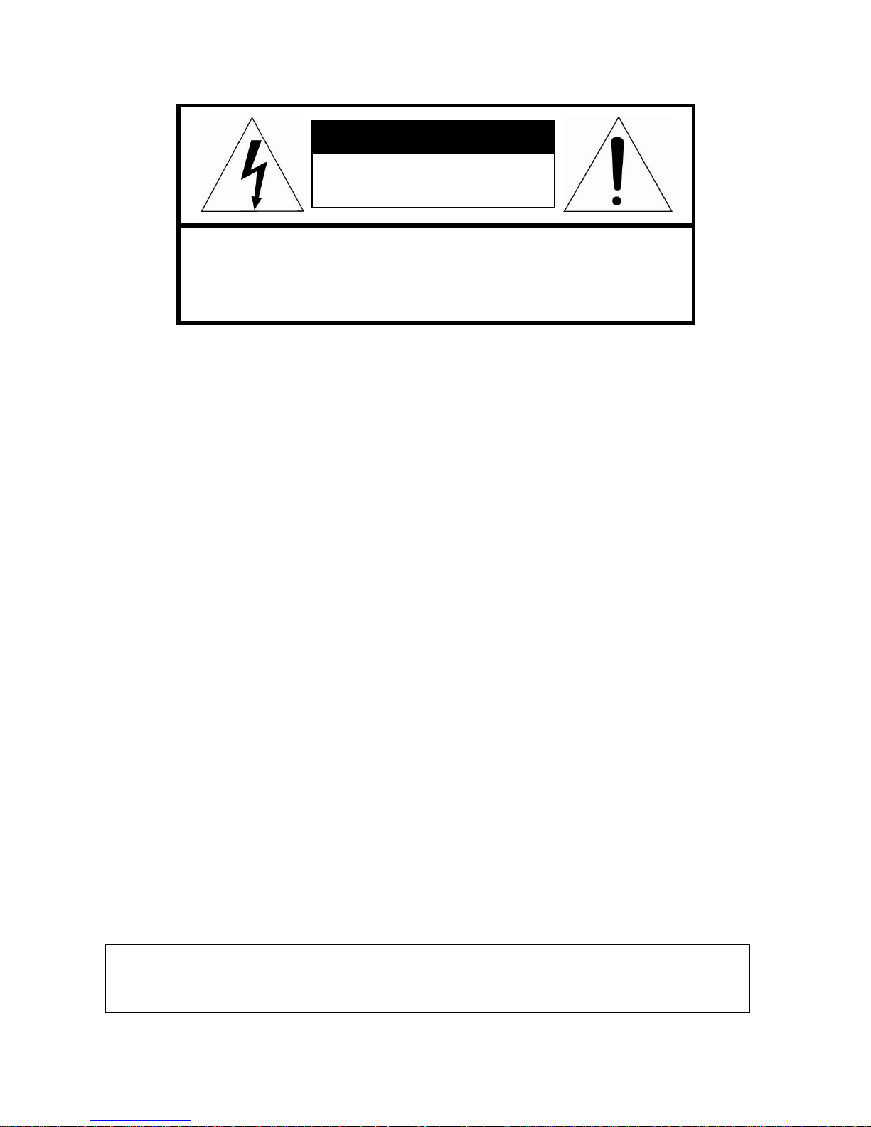
CAUTION
RISK OF ELECTRIC SHOCK
DO NOT OPEN
CAUTION: TO REDUCE THE RISK OF ELECTRIC SHOCK,
DO NOT REMOVE COVER (OR BACK)
NO USER-SERVICEABLE PARTS INSIDE.
REFER SERVICING TO QUALIFIED SERVICE PERSONNEL.
IMPORTANT SAFETY INSTRUCTIONS
1. Read these instructions.
2. Keep these instructions.
3. Heed all warnings.
4. Follow all instructions.
5. Clean only with dry cloth.
6. Do not block any ventilation openings. Install in accordance with the manufacturer’s
instructions.
7. Do not install near any heat sources such as radiators, heat registers, stoves, or other
apparatus (including amplifiers) that produce heat.
8. Do not defeat the safety purpose of the polarized or grounding-type plug. A polarized plug
has two blades with one wider than the other. A grounding type plug has two blades and a
third grounding prong. The wide blade or the third prong is provided for your safety. If the
provided plug does not fit into your outlet, consult an electrician for replacement of the
obsolete outlet.
9. Protect the power cord from being walked on or pinched particularly at plugs, convenience
receptacles, and the point where they exit from the apparatus.
10. Only use attachments/accessories specified by the manufacturer.
11. Unplug this apparatus during lightning storms or when unused for long periods of time.
12. Refer all servicing to qualified service personnel. Servicing is required when the apparatus
has been damaged in any way, such as power-supply cord or plug is damaged, liquid has
been spilled or objects have fallen into the apparatus, the apparatus has been exposed to
rain or moisture, does not operate normally, or has been dropped.
13. CAUTION – THESE SERVICING INSTRUCTIONS ARE FOR USE BY QUALIFIED
SERVICE PERSONNEL ONLY. TO REDUCE THE RISK OF ELECTRIC SHOCK DO NOT
PERFORM ANY SERVICING OTHER THAN THAT CONTAINED IN THE OPERATING
INSTRUCTIONS UNLESS YOU ARE QUALIFIED TO DO SO.
14. Use a Certified/Listed Class 2 power source only.
CE COMPLIANCE STATEMENT
WARNING
This is a Class A product. In a domestic environment this product may cause radio
interference in which case the user may be required to take adequate measures.

5
Table of Contents
Chapter 1 — Introduction ...................................................... Error! Bookmark not defined.
1.1 Features .................................................................................... Error! Bookmark not defined.
Chapter 2 — Installation and Configuration ........................ Error! Bookmark not defined.
2.1 Package Contents .................................................................... Error! Bookmark not defined.
2.2 Mounting the Camera ............................................................... Error! Bookmark not defined.
2.2.1 Locking the Camera ........................................................... Error! Bookmark not defined.
2.3 Basic Configuration of Dome Camera System ....................... Error! Bookmark not defined.
2.4 Setting Dome Camera Video Signal & Coaxial Protocol ........ Error! Bookmark not defined.
2.5 Setting Dome Camera Address (ID) ........................................ Error! Bookmark not defined.
2.6 Connections .............................................................................. Error! Bookmark not defined.
2.7 Getting Started ......................................................................... Error! Bookmark not defined.
Chapter 3 — Program and Operation ................................... Error! Bookmark not defined.
3.1 Dome Camera Selection ........................................................... Error! Bookmark not defined.
3.2 Accessing the On-Screen Menu .............................................. Error! Bookmark not defined.
3.3 How to control the On-Screen Menu ....................................... Error! Bookmark not defined.
3.4 Auto Scan Setup ....................................................................... Error! Bookmark not defined.
3.5 Preset Setup ............................................................................. Error! Bookmark not defined.
3.6 Quick Setting a Preset.............................................................. Error! Bookmark not defined.
3.7 Tour Setup ................................................................................. Error! Bookmark not defined.
3.8 Pattern Setup (Learn Tour)....................................................... Error! Bookmark not defined.
3.9 Privacy Zone Setup .................................................................. Error! Bookmark not defined.
3.10 Camera Setup ......................................................................... Error! Bookmark not defined.
3.11 Dome Communication ............................................................ Error! Bookmark not defined.
3.12 Alarm Setup ............................................................................ Error! Bookmark not defined.
3.13 Configuration Menu (Dome Setup) ........................................ Error! Bookmark not defined.
Appendix A — Specifications ............................................... Error! Bookmark not defined.
Appendix B — Troubleshooting ........................................... Error! Bookmark not defined.
Appendix C — Warranty ........................................................ Error! Bookmark not defined.

1
Chapter 1 — Introduction
1.1 Features
• Built-in optical power zoom camera with True Night Shot function
• 240 Preset positions with the individual camera AE setup
• 8 Tours consist of Presets, Patterns, Auto Scans and other Tours can be programmed with over
300 functions and preset locations. While moving, each Preset scan can be watched in smooth
Vector Scan mode.
• 16 Auto Scans with the normal, the vector, and the random mode and the endless Auto-Pan with
13 speed steps
• 8 Patterns (up to 500 seconds) and 16 Privacy Zones
• 4 Alarm inputs, 2 Alarm outputs (5VTTL)
• Variable speed from 0.1/sec. to 380/sec.
Three Variable speed (SLOW, NORMAL, TURBO)
• Pan/Tilt speed is inversely proportional to the zoom ratio with the option.
• Maximum speed is 380/sec. when Preset command.
• Tilt range is -5 to 90
• Programmable user preferences (alarm, preset, title, etc.)
• 90 Auto Flip
• Function Run menu using DVR without function key (Pattern, Scan …)
• Built-in RS-485 receiver driver (Up to 3999 selectable camera addresses)
• 12VDC for Camera

2
Chapter 2 — Installation and Configuration
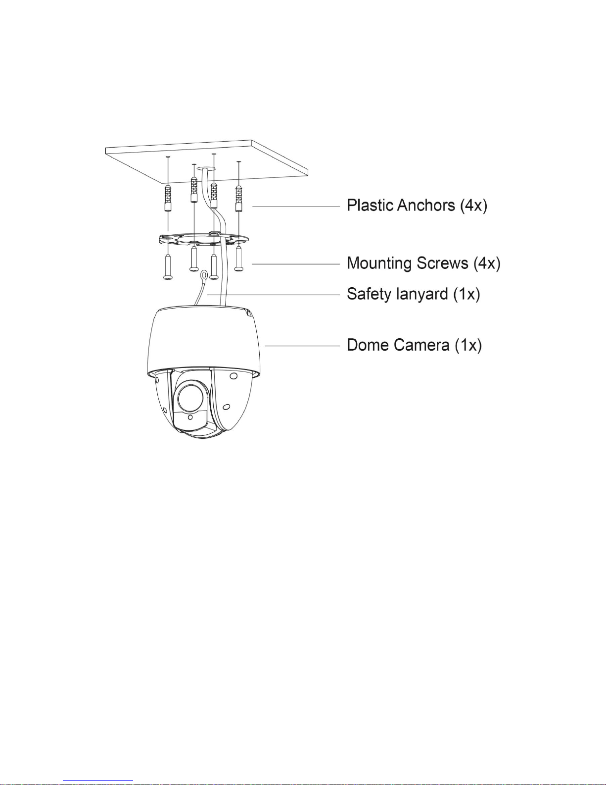
2.1 Package Contents
The package contains the following.
* Dome Camera 1
* Instruction Manual (This Document) 1
* Template Sheet 1
* Mounting Bracket 1
* Safety Lanyard 1
* Accessory Kit 1
1) Mounting screws (PH6 x 35.0) (4)
2) Plastic anchors (4)
3) O-Rings (4)
* Accessory Connector 1
1) 2-Pin Terminal Block (1)
2) 3-Pin Terminal Block (3)
3
2.2 Mounting the Dome Camera
The dome camera is for use in surface or pendent mounting applications, and the mounting
member must be capable of supporting loads of up to 10 lb (4.5 kg). (Pendent mounting must use
pendent mount accessory.)
The dome camera’s mounting bracket should be attached to a structural object, such as hard wood,
wall stud or ceiling rafter that supports the weight of the dome camera.
CAUTION: A silicone rubber sealant must be applied to seal the housing to secure
waterproofing.
CAUTION: Please reset the camera after 30 minutes when installing it in situations colder
than -10°C.
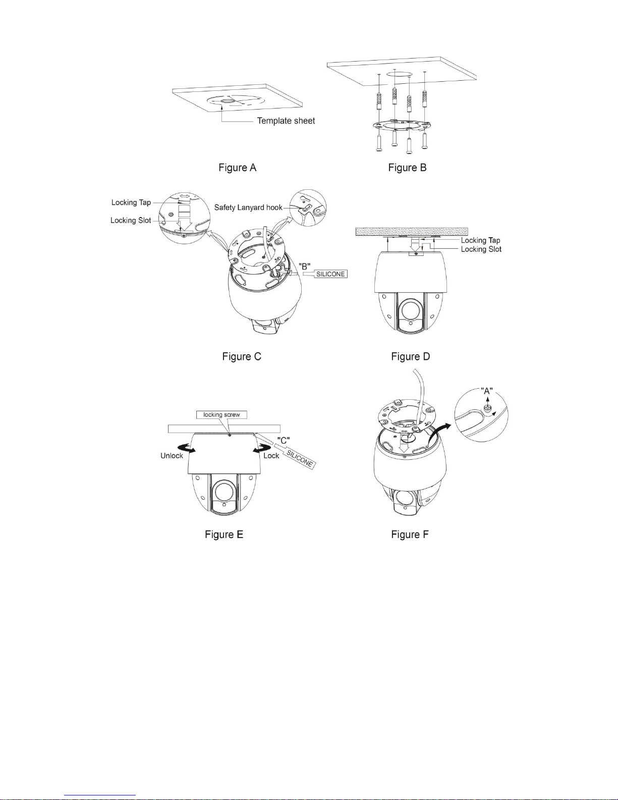
2.2.1 Locking the Dome Camera
1. Make screw holes on the ceiling using the supplied mounting Template Sheet (Figure A).
2. Fix the Mounting Bracket to the ceiling using supplied Anchors (4x) and Mounting Screws (4x)
(Figure B).
3. Hook up the Safety Lanyard to the Safety Lanyard Hook of the Mounting Bracket (Figure C).
4. Align the locking tab on the bracket and the locking slot on the base of the dome (Figure D).
5. Turn the dome to the counterclockwise about 10 degree to the locked position (Figure E).
4
CAUTION: Before installing mounting bracket to surface pre-adjust the four mounting
screws "A" on the base of the dome camera to best match the mounting bracket
locked position. Unscrew the locking screw on the side of the dome's base and
fit the tab of the mounting bracket into the locking slot. Screws "A" should not
be too tight or too loose when the dome is in the locked position. After setting
the proper positions of screws "A" remove the mounting bracket and install it to
the proper surface. If it is too difficult to lock the dome in position after the
mounting bracket has been installed readjust the screws "A" by unscrewing
them a small amount and try to install dome camera again.
5
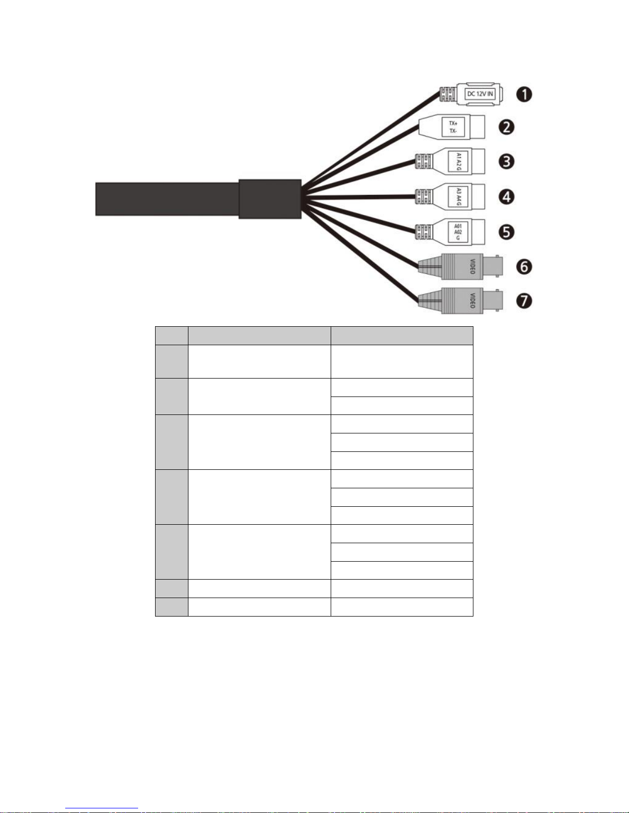
2.3 Basic Configuration of Dome Camera System
No.
Type
Description
1
DC JACK
CAMERA POWER
(12VDC)
2
2-PIN
TERMINAL BLOCK
TX+: RS485+ (A)
TX-: RS485- (B)
3
3-PIN
TERMINAL BLOCK
A1: ALARM INPUT 1
A2: ALARM INPUT 2
G: GND
4
3-PIN
TERMINAL BLOCK
A3: ALARM INPUT 3
A4: ALARM INPUT 4
G: GND
5
3-PIN
TERMINAL BLOCK
AO1: ALARM OUTPUT 1
AO2: ALARM OUTPUT 2
G: GND
6
BNC BLACK
HD OUTPUT
7
BNC YELLOW
CVBS OUTPUT
The dome camera must be installed by qualified service personnel in accordance with all local and
federal electrical and building codes.
6
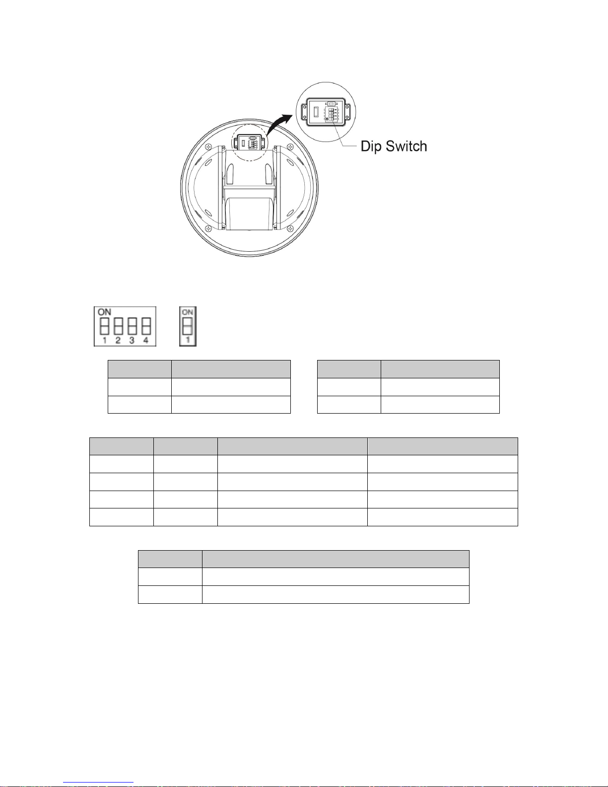
2.4 Setting the Dome Camera (DIP Switch)
NOTE: Open the DIP switch cover and change the setting of DIP switch.
After changing the setting, close the cover tightly to ensure waterproofing.
S1 S2
You can set video signal with D1 and video type with D2 in S1.
S1-D1
Video Signal
S1-D2
Video Type
OFF
HD-TVI Output
OFF
NTSC
ON
AHD Output
ON
PAL
You can set coaxitron protocol with D3 and D4 in S1.
S1-D3
S1-D4
HD-TVI Output
AHD Output
OFF
OFF
Hikvision-C
ACP-PTZ
ON
OFF
Pelco-C
Reserved
OFF
ON
Reserved
Reserved
ON
ON
Reserved
Reserved
You can set CVBS output with D1 in S2.
S2-D1
CVBS Output
OFF
When WDR is on, CVBS output will be disabled.
ON
CVBS output will be enabled (DWDR)

7
2.5 Setting the Dome Camera Address (ID)
To prevent damage, each dome camera must have a unique address (ID).
The factory default setting is 1.
Refer to ‘3.10 Dome Communication’ section for detailed information.
2.6 Connections
• Connecting to the RS-485
The dome camera can be controlled remotely by an external device or control system, such as a
control keyboard, using RS-485 half-duplex serial communications signals.
• Connecting HD Output connector
Connect the HD output (BNC) connector to the video input.
• Connecting CVBS Output connector
Connect the CVBS output (BNC) connector to the video input.
• Connecting Alarms
- A1,A2,A3,A4 (Alarm Input 1,2,3,4)
You can use external devices to signal the dome camera to react on events. Mechanical or
electrical switches can be wired to the A1,A2,A3,A4 (Alarm Input 1,2,3,4) and G (Ground)
connectors.
See Chapter 3 — Program and Operation for configuring alarm input.
- G (Ground)
NOTE: All the connectors marked G or GND are common.
Connect the ground side of the alarm input and/or alarm output to the G (Ground) connector.
- AO1,AO2 (5VTTL Alarm Output 1,2)
The dome camera can activate external devices such as buzzers or lights. Connect the device
to the AO1,AO2 (Alarm Output 1,2) and G (Ground) connectors.
See Chapter 3 — Program and Operation for configuring alarm output.
• Connecting the Power
Connect power of 12VDC for the dome camera.
When using a 12VDC adapter, connect the positive (+) pole to the ‘+’ position and
the negative (-) pole to the ‘-’ position.
 Loading...