

Vista VK-C402DN Install And User Manual

VK-C402DN install and user manual
Installation and user
instructions for Vista’s
VK-C402DN, 540TVL
day/night, MPEG4,
Network camera.

ii
WARNINGS AND CAUTIONS:
TO REDUCE THE RISK OF FIRE OR ELECTRIC SHOCK, DO NOT EXPOSE THIS PRODUCT TO RAIN OR
MOISTURE. DO NOT INSERT ANY METALLIC OBJECTS THROUGH THE VENTILATION GRILLS OR
OTHER OPENINGS ON THE EQUIPMENT.
CAUTION
EXPLANATION OF GRAPHICAL SYMBOLS
The lightning flash with arrowhead symbol, within an equilateral triangle, is intended to alert
the user to the presence of uninsulated "dangerous voltage" within the product's enclosure
that may be of sufficient magnitude to constitute a risk of electric shock to persons.
The exclamation point within an equilateral triangle is intended to alert the user to the
presence of important operating and maintenance (servicing) instructions in the literature
accompanying the product.
PRECAUTIONS
Safety ---------------------------------- Installation -----------------------------
Cleaning ----------------------------------
CAUTION
RISK OF ELECTRNIC SHOCK
DO NOT OPEN
CAUTION: TO REDUCE THE RISK OF ELECTRIC SHOCK,
DO NOT REMOVE COVER (OR BACK).
NO USER-SERVICEABLE PARTS INSIDE.
REFER SERVICING TO QUALIFIED SERVICE PERSONNEL.
Should any liquid or solid object fall into the cabinet,
unplug the unit and have it checked by the qualified
personnel before operating it any further.
Unplug the unit from the wall oulet if it is not going to
be used for several days or more. To disconnect the
cord, pull it out by the plug. Never pull the cord itself.
Allow adequate air circulation to prevent internal heat
build-up. Do not place the unit on surfaces (rugs,
blankets, etc.) or near materials(curtains, draperies)
that may block the ventilation holes.
Height and vertical linearity controls located at the rear
panel are for special adjustments by qualified
personnel only.
Do not install the unit in an extremely hot or humid place
or in a place subject to excessive dust, mechanical
vibration.
The unit is not designed to be waterproof.
Exposure to rain or water may damage the unit.
Clean the unit with a slightly damp soft cloth.
Use a mild household detergent. Never use strong
solvents such as thinner or benzene as they might
damage the finish of the unit.
Retain the original carton and packing materials for safe
transport of this unit in the future.

iii
FCC COMPLIANCE STATEMENT
CE COMPLIANCE STATEMENT
FCC INFORMATION: THIS EQUIPMENT HAS BEEN TESTED AND FOUND TO
COMPLY WITH THE LIMITS FOR A CLASS A DIGITAL DEVICE, PURSUANT TO PART 15 OF
THE FCC RULES. THESE LIMITS ARE DESIGNED TO PROVIDE REASONABLE
PROTECTION AGAINST HARMFUL INTERFERENCE WHEN THE EQUIPMENT IS
OPERATED IN A COMMERCIAL ENVIRONMENT. THIS EQUIPMENT GENERATES, USES,
AND CAN RADIATE RADIO FREQUENCY ENERGY AND IF NOT INSTALLED AND USED IN
ACCORDANCE WITH THE INSTRUCTION MANUAL, MAY CAUSE HARMFUL
INTERFERENCE TO RADIO COMMUNICATIONS. OPERATION OF THIS EQUIPMENT IN A
RESIDENTIAL AREA IS LIKELY TO CAUSE HARMFUL INTERFERENCE IN WHICH CASE
THE USER WILL BE REQUIRED TO CORRECT THE INTERFERENCE AT HIS OWN
EXPENSE.
CAUTION: CHANGES OR MODIFICATIONS NOT EXPRESSLY APPROVED BY THE
PARTY RESPONSIBLE FOR COMPLIANCE COULD VOID THE USER'S AUTHORITY TO
OPERATE THE EQUIPMENT.
THIS CLASS A DIGITAL APPARATUS COMPLIES WITH CANADIAN ICES-003.
CET APPAREIL NUMÉRIQUE DE LA CLASSE A EST CONFORME À LA NORME NMB-003 DU
CANADA.
WARNING
This is a Class A product. In a domestic environment this product may cause radio interference in
which case the user may be required to take adequate measures.

iv
IMPORTANT SAFEGUARDS
1. READ INSTRUCTIONS -- All the safety and operating instructions should be read before the
appliance is operated.
2. RETAIN INSTRUCTIONS -- The safety and operating instructions should be retained for future
reference.
3. CLEANING -- Unplug video monitor or equipment from the wall outlet before cleaning. Do not
use liquid cleaners or aerosol cleaners. Use a damp cloth for cleaning.
4. ATTACHMENTS -- Do not use attachments not recommended by the video monitor or
equipment manufacturer as they may result in the risk of fire, electric shock or injury to persons.
5. WATER AND MOISTURE -- Do not use video monitor or equipment near water - for example,
near a bathtub, washbowl, kitchen sink, laundry tub, in a wet basement, or near a swimming
pool or the like.
6. ACCESSORIES -- Do not place video monitor or equipment on an unstable cart, stand or table.
The video monitor or equipment may fall causing serious injury to a child or adult and serious
damage to the equipment. Wall or shelf mounting should follow the manufacturer's instructions
and should use a mounting kit approved by the manufacturer.
6A. Video monitor or equipment and cart combinations should be moved with care.
Quick stops, excessive force and uneven surfaces may cause the equipment and cart
combination to overturn.
7. VENTILATION -- Slots and openings in the cabinet at the back or bottom are provided for
ventilation and to ensure reliable operation of the video monitor or equipment and to protect it
from overheating. These openings must not be blocked or covered. The openings should never
be blocked by placing the video monitor or equipment on a bed, sofa, rug, or other similar
surface. Video monitor or equipment should never be placed near or over a radiator or heat
register. Video monitor or equipment should not be placed in a built-in installation such as a
bookcase unless proper ventilation is provided.
8. POWER SOURCES -- Video monitor or equipment should be operated only from the type of
power source indicated on the marking label. If you are not sure of the type of power supplied to
your home, consult your video monitor or equipment dealer or local power company. For video
monitor or equipment designed to operate from battery power refer to the operating instructions.
9. GROUNDING OR POLARIZATION -- This video monitor may be equipped with a polarized
alternating - current line plug (a plug having one blade wider than the other). This plug will fit into
the power outlet only one way. This is a safety feature. If you are unable to insert the plug fully
into the outlet, try reversing the plug. If the plug should still fail to fit, contact your electrician to
replace your obsolete outlet. Do not defeat the safety purpose of the polarized plug. Alternate
Warnings - This video monitor is equipped with a three-wire grounding-type plug, a plug having
a third (grounding) pin. This plug will only fit into a grounding-type power outlet. This is a safety

v
feature. If you are unable to insert the plug into the outlet, contact your electrician to replace
your obsolete outlet. Do not defeat the safety purpose of the grounding-type plug.
10. POWER CORDS -- Do not allow anything to rest on the power cord. Do not locate video monitor
or equipment where the cord will be abused by persons walking on it.
11. HEED WARNINGS -- Follow all instructions marked on the video monitor or equipment.
12. LIGHTNING -- For added protection for video monitor or equipment during a lightning storm, or
when it is left unattended and unused for long periods of time, unplug it from the wall outlet and
disconnect the antenna or cable system. This will prevent damage to the video product due to
lightning and power-line surges.
13. OVERLOADING --Do not overload wall outlets and extension cords as this can result in a risk of
fire or electric shock.
14. OBJECT AND LIQUID ENTRY -- Never push objects of any kind into video monitor or
equipment through openings as they may touch dangerous voltage points or short-out parts that
could result in a fire or electric shock. Never spill liquid of any kind on the product.
15. SERVICING -- Do not attempt to service video monitor or equipment yourself as opening or
removing covers may expose you to dangerous voltage or other hazards. Refer all servicing to
qualified service personnel.
16. DAMAGE REQUIRING SERVICE -- Unplug video monitor or equipment from the wall outlet and
refer servicing to qualified service personnel under the following conditions:
A. When the power-supply cord or the plug has been damaged.
B. If liquid has spilled or objects have fallen into the video product.
C. If the video product has been exposed to rain or water.
D. If the video product does not operate normally by following the operating instructions, adjust
only those controls that are covered by the operating instructions as an improper adjustment
of other controls may result in damage and will often require extensive work by a qualified
technician to restore the video product to its normal operation.
E. If the video product has been dropped, or the cabinet damaged.
F. When the video product exhibits a distinct change in performance -- this indicates a need for
service.
17. REPLACEMENT PARTS -- When replacement parts are required, be sure the service
technician has used replacement parts specified by the manufacturer or that have the same
characteristics as the original part. Unauthorized substitutions may result in fire, electric shock or
other hazards.
18. SAFETY CHECK -- Upon completion of any service or repairs to this video product, ask the
service technician to perform safety checks to determine that the video product is in proper
operating condition.
19. FIELD INSTALLATION -- This installation should be made by a qualified service person and
should conform to all local codes.

vi
TABLE OF CONTENTS
1. Product Introduction ........................................................................................................................ 1
1.1 Features ................................................................................................................................ 1
2. NETWORK CAMERA INSTALLATION ........................................................................................... 2
2.1 Package Contents ................................................................................................................. 2
2.2 Dimensions ............................................................................................................................ 2
2.3 FUNCTION DESCRIPTION ................................................................................................... 3
2.4 CONNECTION....................................................................................................................... 4
2.4.1 POWER INPUT TERMINAL ........................................................................................ 4
2.4.2 VIDEO OUT CONNECTOR ......................................................................................... 4
2.4.3 NETWORK CONNECTOR .......................................................................................... 4
2.4.4 VIDEO AUTO IRIS INSTALLATION & ADJUSTMENT ............................................... 4
2.4.5 DC AUTO IRIS LENS INSTALLATION & ADJUSTMENT ........................................... 6
2.4.6 MANUAL IRIS LENS ADJUSTMENT .......................................................................... 7
2.5 BACK FOCUS ADJUSTMENT .............................................................................................. 7
2.6 ZOOM LENS BACK FOCUS ADJUSTMENT ........................................................................ 8
2.7 Network Device IP Assignment ............................................................................................. 9
2.7.1 IP setting...................................................................................................................... 9
2.7.2 Maintenance .............................................................................................................. 10
3. OPERATING CAMERA (Analog Mode) ........................................................................................ 11
3.1 SETTINGS ........................................................................................................................... 11
3.1.1 Main Menu ................................................................................................................. 11
3.1.2 WB ............................................................................................................................. 12
3.1.3 AE .............................................................................................................................. 14

vii
3.1.4 BLC............................................................................................................................ 17
3.1.5 CAM SET................................................................................................................... 17
3.1.6 SPECIAL ................................................................................................................... 20
3.1.7 D&N ........................................................................................................................... 22
3.1.8 DNR ........................................................................................................................... 23
3.1.9 MOTION DET ............................................................................................................ 24
3.1.10 END ......................................................................................................................... 25
4. Operation by Web Browser ........................................................................................................... 26
4.1 Connecting to the NETWORK CAMERA by Web Browser ................................................. 26
4.2 Real-Time Monitoring .......................................................................................................... 26
4.3 NETWORK CAMERA Setting .............................................................................................. 27
4.3.1 Video Setting ............................................................................................................. 27
4.3.2 Alarm Setting ............................................................................................................. 29
4.3.3 System Setting .......................................................................................................... 33
4.4 Help ..................................................................................................................................... 45
5. Appendix ....................................................................................................................................... 46
5.1 Troubleshooting ................................................................................................................... 46
5.2 Preventive Maintenance ...................................................................................................... 46
5.3 Product Specifications ......................................................................................................... 47


1
1. Product Introduction
The VK-C402DN camera provides high-quality colour and monochrome images, this camera has
been designed specifically for closed-circuit television (CCTV) and security surveillance
applications. The NETWORK CAMERA supports the operation through an IP network or via
standard composite coax type applications..
1.1 Features
• High resolution and high performance 1/3" SONY Super HAD CCD technology.
• Full frame rate up to D1 (25fps@720x576, 30fps@720x480) resolution compatible with
MPEG4 standard.
• Superior image quality (540 TV Lines).
• 0.3 Lux(Color) @ F1.2 Sensitivity.
• C/CS, backfocus cam for easy adjustment.
• Auto electronic shutter [1/60(1/50) ~ 1/120,000] and manual electronic shutter modes.
• Full control via the OSD menu key on the rear of the camera.
• Auto and manual white balance modes .
• BLC (Back Light Compensation)
• Day&Night (Auto / Color / B/W)
• AGC (Auto Gain Control)
• Incredible noise reduction for picture quality & file size.
• Sens-up (x2 ~ x128)
• Privacy Zone 4 point.
• MIRROR
• VIDEO OUT(BNC)
• Motion Detection 4point.
• Internal / AC line lock.
• Built-in network interface (10Base-T/100Base-TX) for remote monitoring by PC.
• Interface protocol : TCP/IP, HTTP, UDP, DHCP, RTP, RTSP, SMTP, DDNS.
• Compatible with video- or DC-type lenses with OSD select.
• Quick connect for video or DC lens with 4-pin connector.
• Supports pre & post alarm record in client PC
• Notify events via e-mail
• Quick & Easy set up with user friendly GUI
• Operates in 12VDC.
• Use Certified / Listed Class 2 power supply only.
IMPORTANT: The user of this camera is responsible for checking and complying
with local, state, and federal laws and statutes concerning the recording and
monitoring of audio signals.
2
2. NETWORK CAMERA INSTALLATION
Installation of the camera must be performed by qualified service personnel in accordance with all
local and national electrical and mechanical codes.
2.1 Package Contents
Carefully remove the camera and its accessories from the carton and verify that they were not
damaged in shipment.
The contents of the package includes:
1. Color CCD camera
2. Mini-DIN connector (for video-or dc-type auto-iris lens)
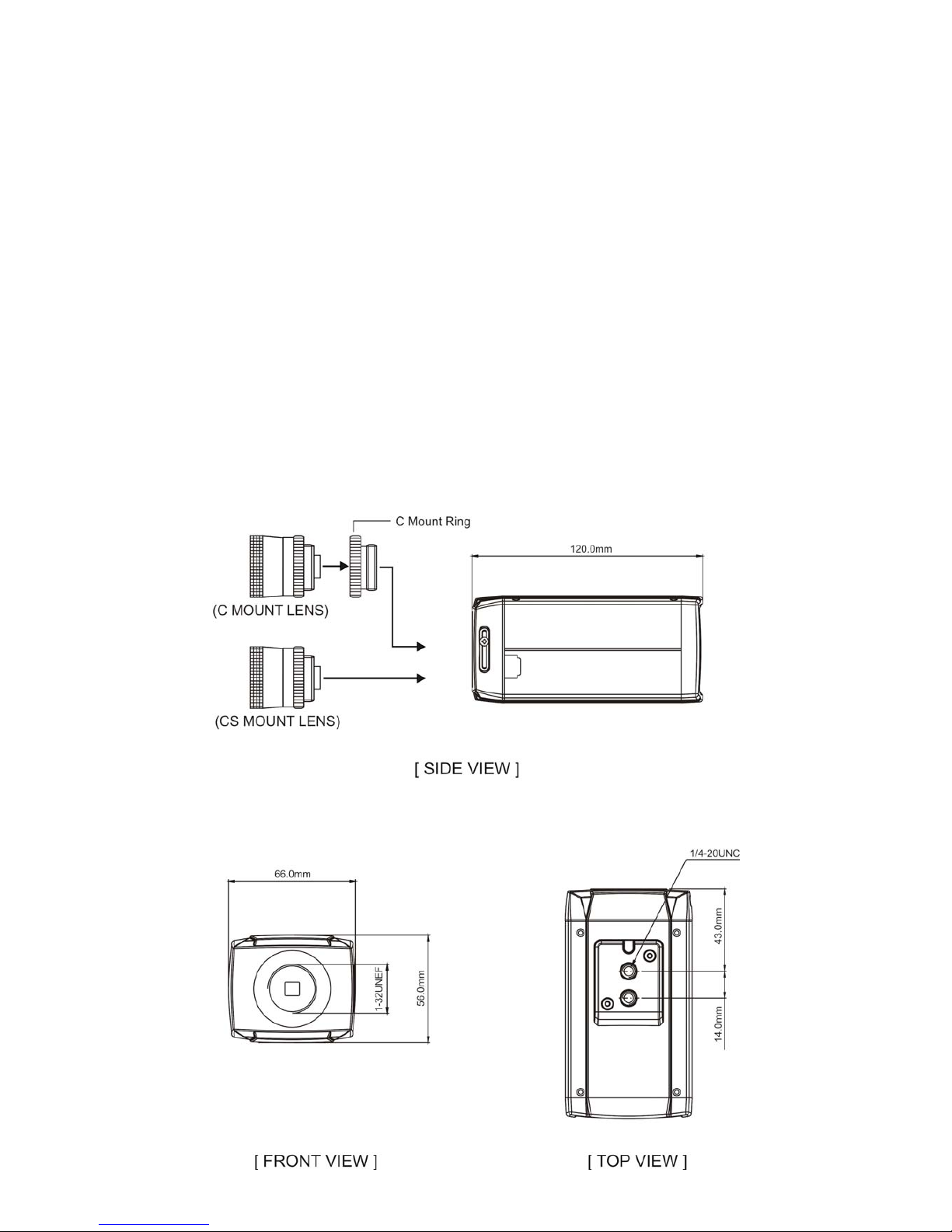
2.2 Dimensions
3
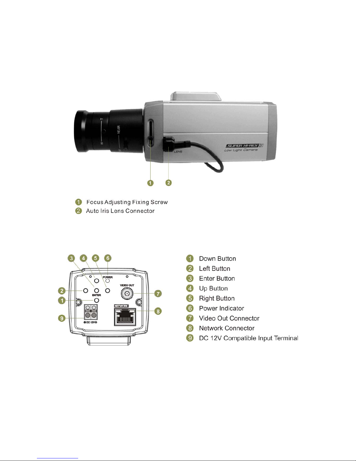
2.3 FUNCTION DESCRIPTION
[SIDE VIEW]
[REAR VIEW]
4
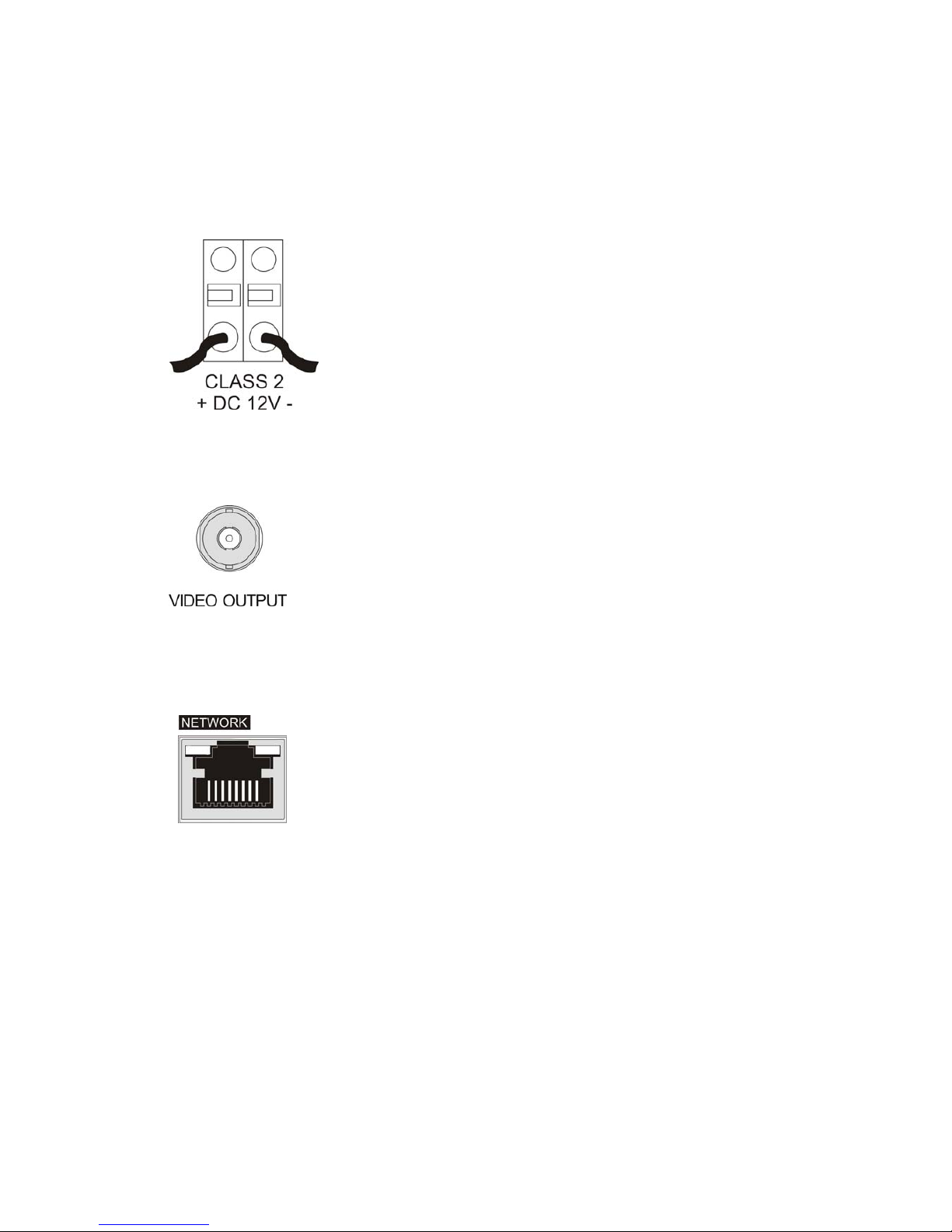
2.4 CONNECTION
2.4.1 POWER INPUT TERMINAL
Power input terminal: Receives DC12V from the power supply.
Use Certified / Listed Class 2 power supply only.
2.4.2 VIDEO OUT CONNECTOR
BNC: This BNC connector provides a 1.0Vp-p/75 ohms composite
video signal.
2.4.3 NETWORK CONNECTOR
Network Connector: The Network Camera supports the operation
through the network. Therefore, it is necessary to connect a
standard RJ-45 cable to it. Generally a cross cable is used for
directly connection to PC, while a direct cable is used for
connection to a hub.
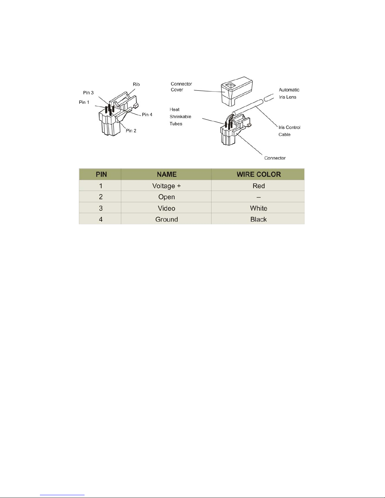
2.4.4 VIDEO AUTO IRIS INSTALLATION & ADJUSTMENT
The camera supports video-type auto iris lenses which adjust to changing light levels. Perform the
following steps to install and adjust a video-type auto iris lens.
5
1. If necessary, solder the lens control wires to the connector supplied with the camera.
2. Attach the video-type auto iris lens to the lens mount on the front of the camera.
3. IMPORTANT: Plug the connector from the lens into the auto iris jack on the side of the
camera. The connector is polarized and can only be inserted into the jack one way.
4. Apply power to the camera.
5. The OSD AE menu in the lens select should be in the “VIDEO↓”.
6. Adjust the focus ring on the lens for an optimum picture. If a picture is not visible, set the
lens for proper exposure by adjusting the ALC (Automatic Level Control) and the level on the
lens. The ALC setting can range between AVG (average) or PK (peak). A midrange setting
is appropriate for most applications.
For ALC adjustments: AVG To slow the reaction of the lens to changing light, set the range
to the AVG setting. Use when there are bright spots in the picture such as lights or glare
from the sun.
PK To increase the speed of the lens reaction to the changing light, set the lens adjustment
to PK so the lens will adjust to the brightest or peak object in the video. Use this setting if
you want to see the brightest object and not the background objects.
For Level adjustments: Adjust the level control for the best picture during the day. A night
adjustment may not provide the proper setting for controlling the light during the day.
7. Set the back focus of the camera before the final adjustment of the video level.
8. If the auto iris has a gain adjustment and the picture oscillates between open and closed
under bright lights, slowly turn the gain adjustment counter clockwise until the oscillating
6
stops. Increase the light getting to the camera by adjusting the level control and re-adjusting
the gain control.
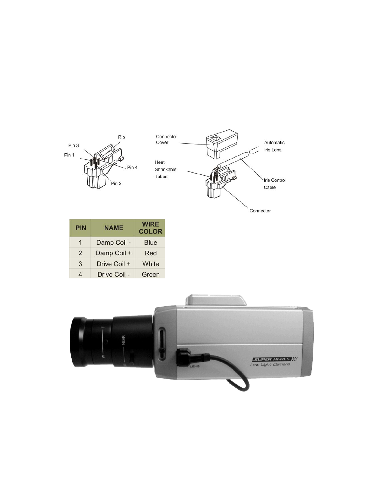
2.4.5 DC AUTO IRIS LENS INSTALLATION & ADJUSTMENT
The camera supports DC-type auto iris lenses. Perform the following steps to install and adjust a
DC-type auto iris lens.
1. Solder the lens control wires to the connector supplied with the camera.
2. Attach the DC-type auto iris lens to the lens mount
on the front of the Camera.
3. Plug the connector into the auto iris jack on the
back of the camera. The connector is polarized and
can only be inserted into the Jack one way.
4. Apply power to the camera.
5. The OSD AE menu in the lens select should be in the "DC↓".

7
6. Adjust the auto iris lens for an optimum picture using the LEVEL control on the "DC↓" of the
OSD AE MENU.
2.4.6 MANUAL IRIS LENS ADJUSTMENT
When using a manual iris lens, turn the iris ring on the lens to the OPEN position and adjust the
manual iris for the appropriate range. Adjust during the brightest conditions, opening the lens to the
minimum f-stop yielding a good picture under the brightest scene conditions. Do not saturate the
picture.
Manual iris lenses are generally used internally only
2.5 BACK FOCUS ADJUSTMENT
For best results, perform back focus adjustments at night or while using a #6 or #8 welder's glass in
front of the lens. The focus of the camera will change slightly if the camera iris was adjusted on a
light scene, then changes to a dark scene. However, the camera will remain in focus if the iris was
focused on a dark scene and the scene lightens.
1. The lens should be mounted on the camera before applying power.
2. If a picture is visible, focus on the picture. If the picture is not visible, open the iris on the
lens. Open the lens as wide as possible by placing the welder's glass in front of the lens
and forcing the lens to automatically open.
3. When the iris is open to the widest point, re-adjust the focus for clear picture. If a clear
picture is not possible, set the focus ring to midrange.
4. Loosen the back focus lock screw.
5. Adjust the back focus ring for a clear picture.
6. Tighten the back focus lock screw.
7. Fine tune the focus with the focus ring on the lens.
8. Remove the welder's glass from in front of the lens.
9. Adjust the iris of the lens for the best picture quality.

8
2.6 ZOOM LENS BACK FOCUS ADJUSTMENT
The objective of back focusing a zoom lens is similar to that of a fixed focal length camera except
the back focus is also adjusted to maintain the focus when "zooming" the lens in and out on a scene.
1. Choose an object at the farthest range set for viewing with a zoom lens.
2. Make sure the iris of the lens is wide open. Do this by adjusting the camera at night or use
a welders glass in front of the lens.
3. Adjust the focus to the stop on the far range.
4. Adjust the zoom on the lens to obtain the widest picture.
5. Loosen the back focus lock screw.
6. Adjust the back focus ring for the clearest picture.
7. Tighten the back focus lock screw.
8. Adjust the zoom on the lens to the far telephoto position.
9. Adjust the back focus ring for the clearest picture.
10. Adjust the zoom on the lens back to the widest picture.
11. Loosen the back focus screw.
12. Re-adjust the back focus for the clearest picture.
13. Tighten the back focus lock screw.
14. Repeat the previous steps as necessary to maintain a clear picture throughout the entire
zoom range.
9
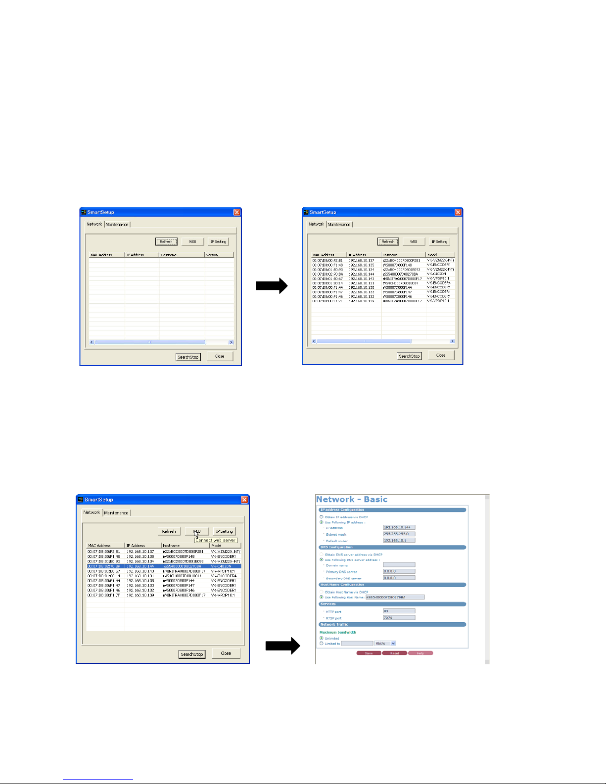
2.7 Network Device IP Assignment
When a camera, Encoder or Decoder is first connected to the network it has no IP address. So, it is
necessary to allocate an IP address to the device with the IP Setting Utility on the CD.
Open the program folder installed with the provided CD and execute “Smart Setup”.
2.7.1 IP setting
2.7.1.1 Web button
Select network device and click the ‘WEB’ button.
Users enter a network device IP directly.
 Loading...