

Vista VK2-REC04HDW Quick Start Manual
VK2-REC04HDW
Wireless Network Video Recorder
Quick Start Guide
Version 1.2 – Sept 2013
Vista VK2-REC04HDW Quick Start Guide
2
1. Hardware Overview
This installation guide provides detailed information and instructions for the VK2-REC04HDW Network Video
Recorder.
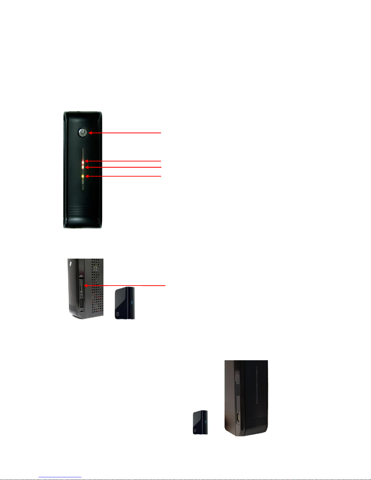
• Front View
• Right Side View
• Left Side View
REC LED : Emitting during recording
Power LED : See ** below
Power On/Standby button
Network LED : Emitting when Ethernet cable connected
** Power status
Red : Standby state
Orange : In booting progress
Green : Normal state
Sata hard disc drive
Extra Sata connector : To expand hard disc drive
adding to installed drive inside
1 USB Port : To connect external hard disk
drives for data backup.
Vista VK2-REC04HDW Quick Start Guide
3
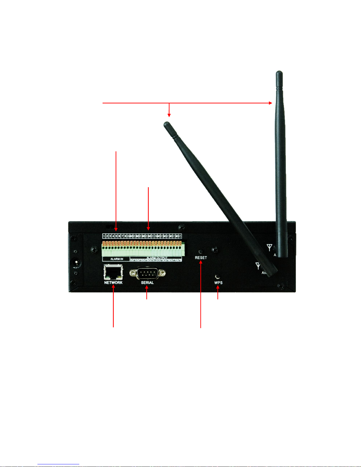
• Rear View
** Only working with wireless antennas
- NO Devices
- DC 30V 1A max
- AC 125V 0.5A max
8 Ports Alarm Output
- NC/NO Devices selectable
- TTL Level Input
8 Ports Sensor Input
- 2.4GHz wireless antennas
Gigabit Ethernet Port :
To connect to IP cameras
and Client software
RS232 Port :
To connect devices
such as POS
Reset Button :
To return all configurations
to factory default values
WPS Button :
To automatic detect and
connect to wireless cameras
WiFi Antennas
Vista VK2-REC04HDW Quick Start Guide
4
2. Installation
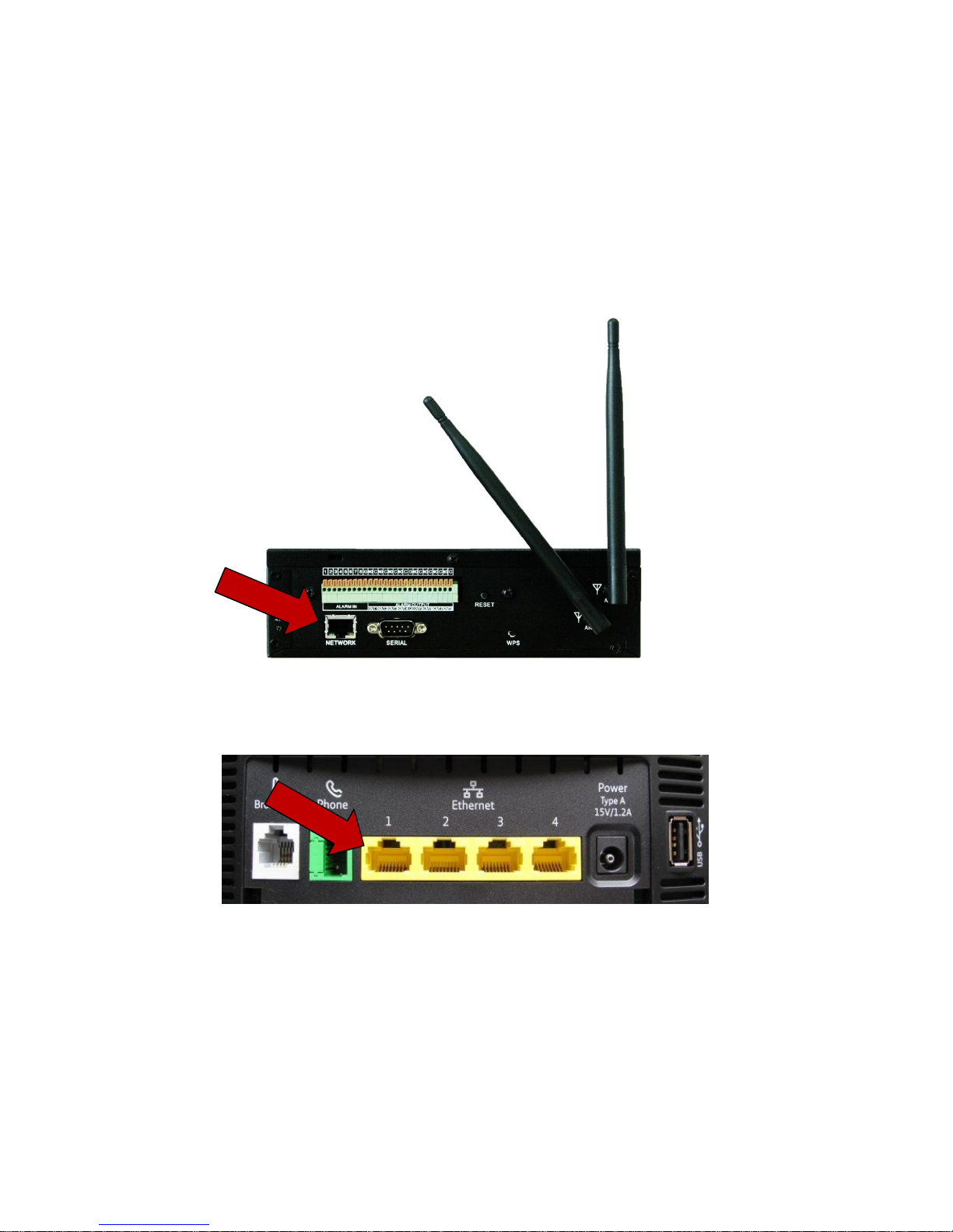
2.1 Connecting Power and Network
• Connecting to the RJ-45
Connect a standard RJ-45 cable to the network port of the broadband router (or Network Switch) and
the other end of the cable to the network port on the NVR.
VK2-REC04HDW
Example Broadband Router
Network Connections
Vista VK2-REC04HDW Quick Start Guide
5
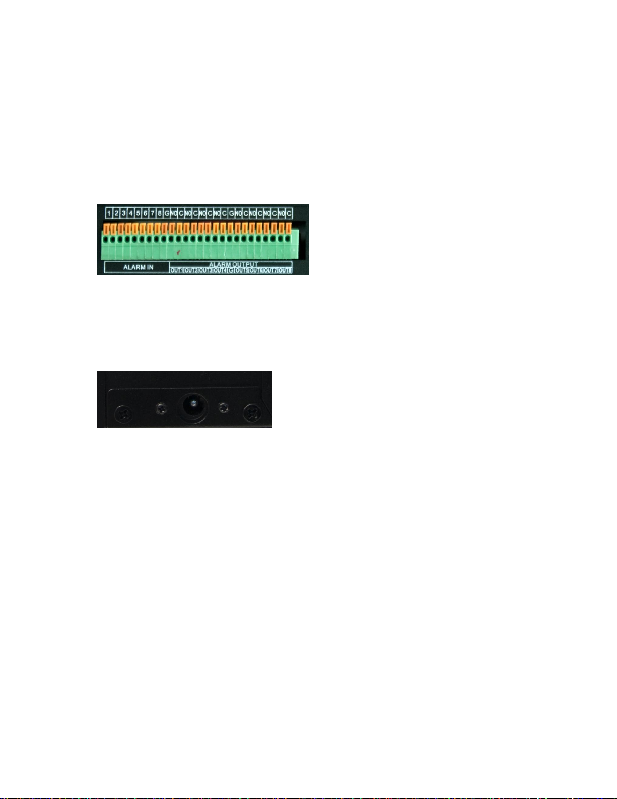
• Connecting Alarms
Alarm Input :
You can use external devices to signal the network camera to react on events. Mechanical or electrical
switches can be wired to the Alarm Input 1~8 and GND (Ground) connectors.
GND(Ground) :
Connect the ground side of the alarm input to the G (Ground) connector.
Alarm Output :
The network camera can activate external devices such as buzzers or lights. Connect the devices
to the Alarm Output 1~8 and C(Common) connectors.
• Connecting the Power
Connect the DC power adaptor to the NVR. As the power is supplied, the Power LED will start
flickering, indicating stand-by mode. Pressing the POWER button will turn the power on and the
Power LED will light.
 Loading...