

Vista VK2-PVMxxDEC Series, VK2-PVM18DEC, VK2-PVM27DEC, VK2-PVM32DEC User Manual
1
User Manual
VK2-PVMxxDEC
User manual
For 18.5, 27 and 31.5” models

2
Lease read this manual thoroughly before use and keep it handy for future reference.

3
Contents
1. Overview .................................................................................................................................................. 8
1.1 Package Contents ......................................................................................................................... 8
1.2 Connection Description .................................................................................................................. 8
2. Installation ............................................................................................................................................... 9
2.1 Starting System .......................................................................................................................... 10
2.2 Quick Setup ................................................................................................................................ 11
2.2.1 Account ............................................................................................................................. 11
2.2.2 System............................................................................................................................... 11
2.2.3 Network ............................................................................................................................. 12
2.2.4 Time/Date .......................................................................................................................... 12
2.2.5 Easy Installation Wizard....................................................................................................... 13
3. Live Screen Configuration ........................................................................................................................ 14
3.2 Quick menu ................................................................................................................................ 15
3.2.1 Channel Assign ................................................................................................................... 16
4. Setup menu ............................................................................................................................................ 17
4.1 Main standard buttons in Setup menu ........................................................................................... 18
4.2 SYSTEM ..................................................................................................................................... 19
4.2.1 System............................................................................................................................... 19
4.2.2 Time/Date .......................................................................................................................... 21
4.2.3 Account > User ................................................................................................................... 22
4.2.4 Configuration (Config) ......................................................................................................... 24
4.3 CAMERA ..................................................................................................................................... 26
4.3.1 Channel ............................................................................................................................. 26
4.4 DEVICE ...................................................................................................................................... 27
4.4.1 Display ............................................................................................................................... 27
4.4.2 Serial Device > Serial Device ................................................................................................ 29
4.5 NETWORK .................................................................................................................................. 30
4.5.1 Basic > WAN Port ............................................................................................................... 30
5. Displaying Media files .............................................................................................................................. 31
5.1 AVI Conversion program .............................................................................................................. 31
5.2 Adding Media file to the Monitor ................................................................................................... 32
6. Product Specfication .................................................................................... Error! Bookmark not defined.

4
Before You Begin
Read these instructions before installing or operating this product.
Note: This installation should be made by a qualified service person and should conform to
local codes.
This manual provides installation and operation information. To use this document, you must
have the following minimum qualifications:
A basic knowledge of CCTV systems and components
A basic knowledge of electrical wiring and low-voltage electrical connections
Intended use
Only use this product for its designated purpose; refer to the product specification and user
documentation.
Customer Support
For assistance in installing, operating, maintaining and troubleshooting this product refer to this
document and any other documentation provided. If you still have questions, please contact
Norbain Technical Support and Sales:
Norbain SD, Inspired, Easthampstead Road, Bracknell RG12 1YQ.
UK +44 (0) 118 912 5000
Note: You should be at the equipment and ready with details before calling Technical Support.
Conventions Used in this Manual
Boldface or button icons highlight command entries. The following WARNING, CAUTION
and Note statements identify potential hazards that can occur if the equipment is not handled
properly:
* WARNING:
Improper use of this equipment can cause severe bodily injury or equipment
damage.
** Caution:
Improper use of this equipment can cause equipment damage.
Note: Notes contain important information about a product or procedure.
5
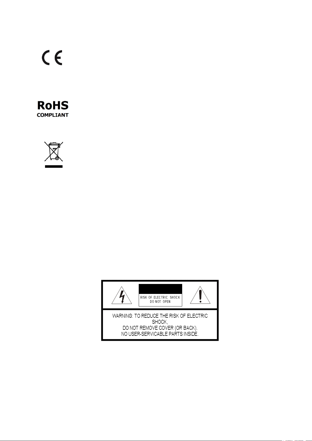
This apparatus is manufactured to comply with the radio interference.
A Declaration of Conformity in accordance with the following EU standards has been
made. The manufacturer declares that the product supplied with this document is
compliant the provisions of the EMC Directive 2004/108/EC, the CE Marking
Directive 93/68 EEC and all associated amendments.
All lead-free products offered by the company comply with the requirements of
the European law on the Restriction of Hazardous Substances (RoHS) directive:
2011/65/EU, which means our manufacture processes and products are strictly
“lead-free” and without the hazardous substances cited in the directive.
The crossed-out wheeled bin mark symbolizes that within the European Union the
product must be collected separately at the product end-of-life. This applies to
your product and any peripherals marked with this symbol. Do not dispose of these
products as unsorted municipal waste.
* This symbol indicates electrical warnings and cautions.
** This symbol indicates general warnings and cautions.
NORBAIN SD reserves the right to make changes to the product and specification of the product
from time to time without prior notice.
WARNINGS AND CAUTIONS:
To reduce the risk of fire or electric shock, do not insert any metallic objects through the ventilation
grills or other openings on the equipment.

6
IMPORTANT SAFEGUARDS
1. Read these instructions.
2. Keep these instructions.
3. Heed all warnings.
4. Follow all instructions.
5. Do not use this apparatus near water.
6. Clean only with dry cloth.
7. Do not block any ventilation openings. Install in accordance with the
manufacturer's instructions.
8. Do not install near any heat sources such as radiators, heat registers, stoves, or
other apparatus (including amplifiers) that product heat.
9. Do not defeat the safety purpose of the polarized or grounding-type plug. A
polarized plug has two blades with one wider than the other. A grounding type
plug has two blades and a third grounding prong. The wide blade or the third
prong is provided for your safety. If the provided plug does not fit into your
outlet, consult an electrician for replacement of the obsolete outlet.
10. Protect the power cord from being walked on or pinched particularly at plugs,
convenience receptacles, and the point where they exit from the apparatus.
11. Only use attachments/accessories specified by the manufacturer.
12. Unplug this apparatus during lightning storms or when unused for long periods
of time.
13. Refer all servicing to qualified service personnel. Servicing is required when
the apparatus has been damaged in any way, such as power-supply cord or
plug is damaged, liquid has been spilled or objects have fallen into the
apparatus, the apparatus has been exposed to rain or moisture, does not
operate normally, or has been dropped.
14. CAUTION - THESE SERVICING INSTRUCTIONS ARE FOR USE BY
QUALIFIED SERVICE PERSONNEL ONLY. TO REDUCE THE RISK OF
ELECTRIC SHOCK DO NOT PERFORM ANY SERVICING OTHER THAN
THAT CONTAINED IN THE OPERATING INSTRUCTIONS UNLESS YOU ARE
QUALIFIED TO DO SO.
15. IEC60950-1/UL60950-1 or Certified/Listed Class 2 power source only.

7
CE COMPLIANCE STATEMENT
WARNING
This is a Class A product. In a domestic environment this product may cause radio
interference in which case the user may be required to take adequate measures.
CAUTION
RISK OF EXPLOSION IF BATTERY IS REPLACED BY AN INCORRECT TYPE.
DISPOSE OF USED BATTERIES ACCORDING TO THE INSTRUCTIONS.
8
1. Overview
1.1 Package Contents
The device package contents consist of the following:
Note
Please check all components involved.
Table 1-1 Package contents
No
Name
No
Name
1
VK2-PVMxxDEC Monitor
2
Quick guide
3
Program CD
4
M6X10 SCREW *4
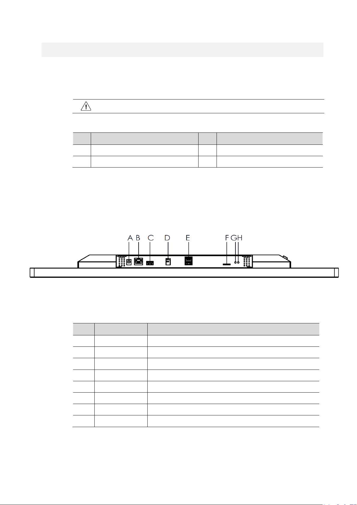
1.2 Connection Description
Each part is listed in the below:
Figure 1-1 Name and Connection of each front section
Table 1-2 Name and Function of each front section
No.
Name
Function
A
DC JACK
DC INPUT (27” & 31.5”:24V,18.5”:12V)
B
LAN/PoE+
Ethernet 10/100Base-T, RJ45 connector With PoE+ (IEEE 802.3AT)
C
USB2 port
USB port for Monitor Firmware upgrade (27” & 31.5” Only)
D
ALARM OUTPUT
Alarm output connector.
E
USB1 port
USB port for mouse connection and Decoder Firmware upgrade
F
Micro SD
Store media file.
G
LAN LED
Network connection indicator
H
Power LED
Power indicator
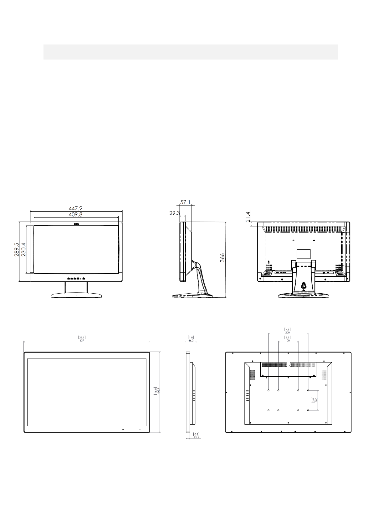
9
2. Installation
• VK2-PVM27/32DEC Use appropriate screws to mount VESA bracket (VESA HOLD 100 x 100
& 100x 200/Screw hole: M6 x 10mm), failure to do so may cause serious injury.
• Ensure that the VESA bracket has an adequate size mounting plate, screws and/or fixings to
support the weight of the monitor and bracket to the surface to which it is being attached.
Failure to do so may cause serious injury.
• If there is any doubt of the suitability of a mount or fixing method, a qualified technician
should be consulted.
VK2-PVM18DEC
VK2-PVM27DEC
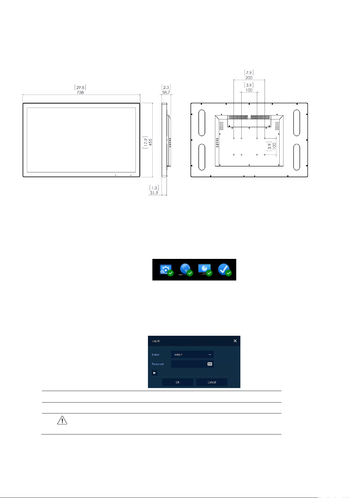
10
VK2-PVM32DEC
Figure 2-1 Dimension (unit: mm)
2.1 Starting System
On power up the following icons will appear sequentially:
1
Switching on initialize with below icons in order.
2
When the buzzer sounds, the start screen will be presented.
3
In Log in screen, enter the ID, Password and press OK.
Note
Default ID & Password is admin/admin.
Attention
Please change password after login due to security.
 Loading...