

Vista VK2-600PTZ Configuration And User Manual
Configuration and User manual

II
VK2-600PTZ User manual
III
VK2-600PTZ User manual
TO REDUCE THE RISK OF FIRE OR ELECTRIC SHOCK, DO NOT EXPOSE THIS PRODUCT TO RAIN
OR MOISTURE. DO NOT INSERT ANY METALLIC OBJECTS THROUGH THE VENTILATION GRILLS OR
OTHER OPENINGS ON THE EQUIPMENT.
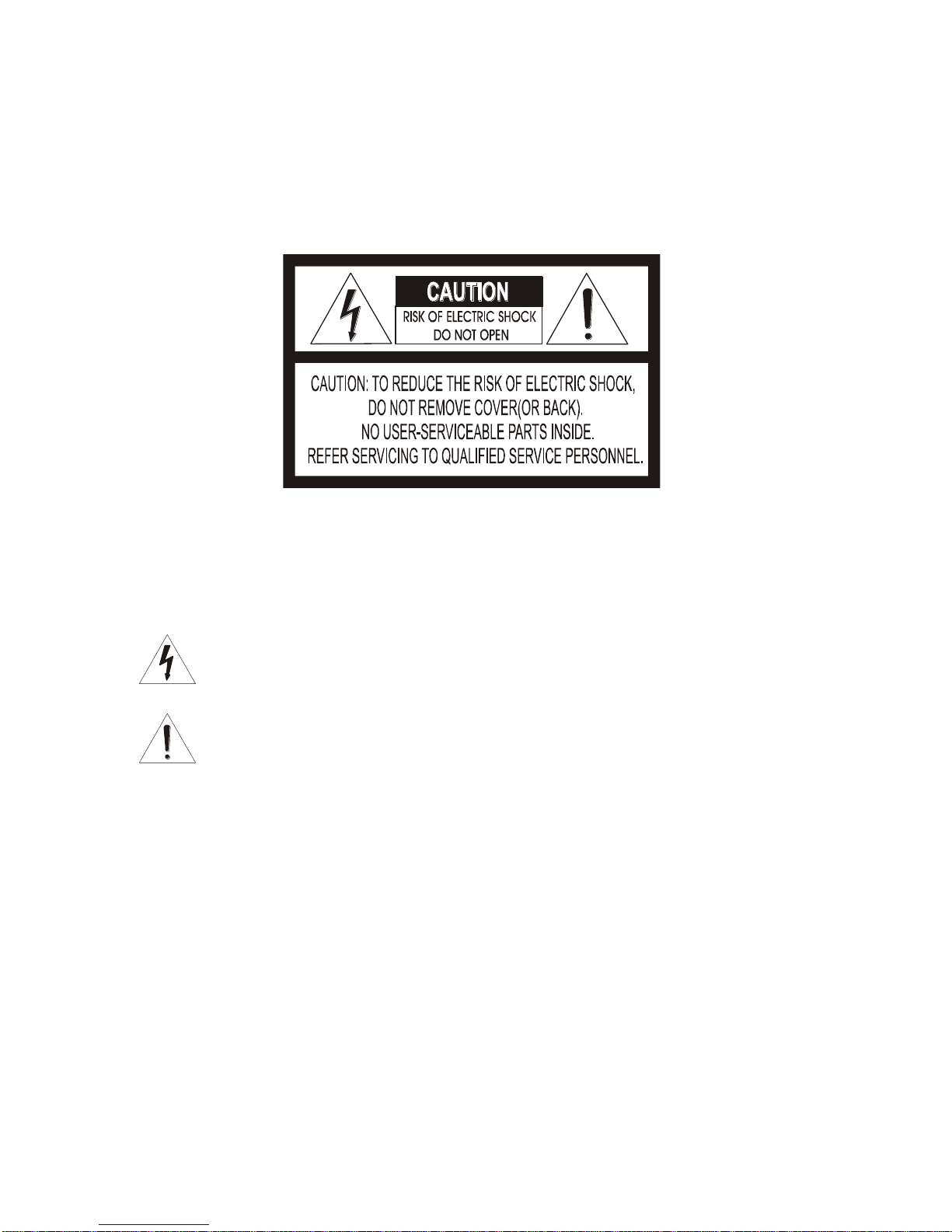
EXPLANATION OF GRAPHICAL SYMBOLS
The lightning flash with arrowhead symbol, within an equilateral triangle, is intended to
alert the user to the presence of uninsulated "dangerous voltage" within the product's
enclosure that may be of sufficient magnitude to constitute a risk of electric shock to
persons.
The exclamation point within an equilateral triangle is intended to alert the user to the
presence of important operating and maintenance (servicing) instruction in the literature
WARNING
CAUTION
accompanying the product.

IV
VK2-600PTZ User manual
CE COMPLIANCE STATEMENT
WARNING
THIS IS A CLASS A PRODUCT. IN A DOMESTIC ENVIRONMENT THIS
PRODUCT MAY CAUSE RADIO INTERFERENCE IN WHICH CASE THE USER
MAY BE REQUIRED TO TAKE ADEQUATE MEASURES.

V
VK2-600PTZ User manual
IMPORTANT SAFETY INSTRUCTIONS
1. Read these instructions.
2. Keep these instructions.
3. Heed all warnings.
4. Follow all instructions.
5. Do not use this apparatus near water.
6. Clean only with dry cloth.
7. Do not block any ventilation openings. Install in accordance with the manufacturer‘s
instructions.
8. Do not install near any heat sources such as radiators, heat registers, stoves, or other
apparatus (including amplifiers) that produce heat.
9. Do not defeat the safety purpose of the polarized or grounding-type plug. A polarized
plug has two blades with one wider than the other. A grounding type plug has two blades
and a third grounding prong. The wide blade or the third prong are provided for your
safety. If the provided plug does not fit into your outlet, consult an electrician for
replacement of the obsolete outlet.
10. Protect the power cord from being walked on or pinched particularly at plugs,
convenience receptacles, and the point where they exit from the apparatus.
11. Only use attachments/accessories specified by the manufacturer.
12. Use only with the cart, stand, tripod, bracket, or table specified by the
manufacturer, or sold with the apparatus. When a cart is used, use
caution when moving the cart/apparatus combination to avoid injury
from tip-over.
13. Unplug this apparatus during lightning storms or when unused for
long periods of time.
14. Refer all servicing to qualified service personnel. Servicing is required when the
apparatus has been damaged in any way, such as power-supply cord or plug is damaged,
liquid has been moisture, does not operate normally, or has been dropped.
15. CAUTION – THESE SERVICING INSTRUCTIONS ARE FOR USE BY QUALIFIED
SERVICE PERSONNEL ONLY. TO REDUCE THE RISK OF ELECTRIC SHOCK DO
NOT PERFORM ANY SERVICING OTHER THAN THAT CONTAINED IN THE
OPERATING INSTRUCTIONS UNLESS YOU QRE QUALIFIED TO DO SO.
16. Use satisfy clause 2.5 of IEC60950-1/UL60950-1 or Certified/Listed Class 2 power
source only.

VI
VK2-600PTZ User manual
Table of Contents
Chapter 1 — Introduction........................................................................................................... 1
1.1 Features ............................................................................................................................................. 1
Chapter 2 — Installation and Configuration ......................................................................... 2
2.1 Package Contents ........................................................................................................................... 2
2.2 Installation ......................................................................................................................................... 3
2.3 Basic Configuration of Dome Camera System ........................................................................ 5
2.4 Connections ...................................................................................................................................... 6
2.5 IP Assignment .................................................................................................................................. 7
2.6 Getting Started ................................................................................................................................. 8
Chapter 3 — Operation by Web Browser .............................................................................. 9
3.1 Access from a browser .................................................................................................................. 9
3.2 Access from the internet ............................................................................................................. 10
3.3 Setting the admin password over a secure connection ...................................................... 10
3.4 Live View Page ............................................................................................................................... 10
3.5 Network Camera Setup ................................................................................................................ 12
3.5.1 Basic Configuration ............................................................................................................... 13
1) Users .......................................................................................................................... 13
2) Network ...................................................................................................................... 14
3) Video & Image ........................................................................................................... 15
4) Audio .......................................................................................................................... 17
5) Date & Time ............................................................................................................... 18
3.5.2 Video & Image ......................................................................................................................... 19
3.5.3 Audio ......................................................................................................................................... 20
3.5.4 Event .......................................................................................................................................... 20
1) Event-In ...................................................................................................................... 20
2) Event-Out ................................................................................................................... 24
3) Event Map .................................................................................................................. 30
3.5.5 System ...................................................................................................................................... 31
1) Information ................................................................ ................................................ 31
2) Security ...................................................................................................................... 32
3) Date & Time ............................................................................................................... 35
4) Network ...................................................................................................................... 36
5) Language ................................................................................................................... 43
6) Maintenance .............................................................................................................. 44
7) Support ...................................................................................................................... 45
3.6 PTZ Control ..................................................................................................................................... 46

VII
VK2-600PTZ User manual
3.7 Help ................................................................................................................................................... 47
3.8 Resetting to the factory default settings ................................................................................. 48
3.9 System Requirement for Web Browser ................................................................................... 48
Chapter 4 — Program and Operation (RS485 telemetry) ................................................ 49
4.1 How to control the On-Screen Menu ........................................................................................ 49
4.2 Accessing the On-Screen Menu ................................................................................................ 49
4.3 Auto Scan ........................................................................................................................................ 50
4.4 Preset ................................................................................................................................................ 51
4.5 Quick setting a Preset .................................................................................................................. 54
4.6 Tour ................................................................................................................................................... 54
4.7 Pattern (Learn Tour) ...................................................................................................................... 55
4.8 Area Title .......................................................................................................................................... 56
4.9 Privacy Zone .................................................................................................................................. 57
4.10 Camera Menu ................................................................................................................................ 58
• FOCUS CONTROL ....................................................................................................... 58
• WB (White Balance) CONTROL ................................ .................................................. 59
• AE CONTROL ................................................................................................ .............. 59
• DNR CONTROL ............................................................................................................ 60
• LINE LOCK CONTROL ................................................................................................ 60
4.11 Dome Setup .................................................................................................................................. 61
• LANGUAGE SETUP ..................................................................................................... 61
• HOME FUNCTION SETUP ................................ ........................................................... 61
• OSD DISPLAY .............................................................................................................. 62
• VIEW ANGLE SETUP ................................................................................................... 63
• INITIALIZE DATA ......................................................................................................... 64
• ORIGIN OFFSET .......................................................................................................... 65
• DOME RESET .............................................................................................................. 66
• SYSTEM MENU ............................................................................................................ 66
• SYSTEM INFORMATION ............................................................................................. 68
4.12 Factory Setup ............................................................................................................................... 68
5 Dome Communication (RS485 Addressing etc) ....................................................................... 69
Appendix A — Specifications ................................................................................................. 70
Appendix B — Troubleshooting............................................................................................. 73
Appendix C — Glossary ........................................................................................................... 73

1
VK2-600PTZ User manual
Chapter 1 — Introduction
1.1 Features
Dual video streams simultaneously at full frame rate in all resolutions up to D1 (720X480 in
NTSC, 720X576 in PAL) using Motion JPEG and H.264 (or MPEG-4).
Built-in 22:1 optical zoom with True Day/Night operation.
Intelligent capabilities such as enhanced video motion detection. The encoder‘s external inputs
and outputs can be connected to devices such as sensors and relays, enabling the system to
react to alarms and activate lights or open/close doors.
Supports two-way audio.
Logs all user access, and lists currently connected users. Also, full frame rate video can be
provided over HTTPS.
Interface Protocol: TCP/IP, UDP, IPv4/v6, HTTP, HTTPS, QoS, FTP, SNMP, uPnP, RTP,
RTSP, RTCP, DHCP, ARP.
120 Preset positions with the individual Camera AE setup.
4 Tours consist of Presets, Patterns, Auto Scans and other Tours can be programmed with
over 150 functions and Preset locations. While moving, each Preset scan can be watched in
smooth Vector Scan mode.
4 Auto Scans with the normal, the vector, and the random mode and the Endless Auto-Pan
with 13 speed steps.
4 Patterns (up to 200 second) and 4 Privacy Zones.
8 Area Titles.
1 Alarm input / 1 Alarm output (TTL ON/OFF)
Variable speed from 0.1 /sec to 380 /sec.
Three Variable speed (SLOW, NORMAL, TURBO).
Turbo speed is 380 /sec with Ctrl key pressed.
Pan / Tilt speed is inversely proportional to the zoom ratio with the option.
Maximum speed is 380 /sec when Preset command.
Auto Calibration from 0.1 to 6 (Tilt range is 0 to 180 ).
Programmable user preferences (alarm, preset, title, etc.).
180 Digital Flip.
Up to 255 selectable camera addresses.
Multi-language Menu Display, Password Confirmation.
Function Run menu using DVR without function key (Pattern, Scan,..)
Built-in RS-485 receiver driver.
12VDC or PoE operation.
Use a Certified/Listed Class 2 power supply only.
2
VK2-600PTZ User manual
Chapter 2 — Installation and Configuration
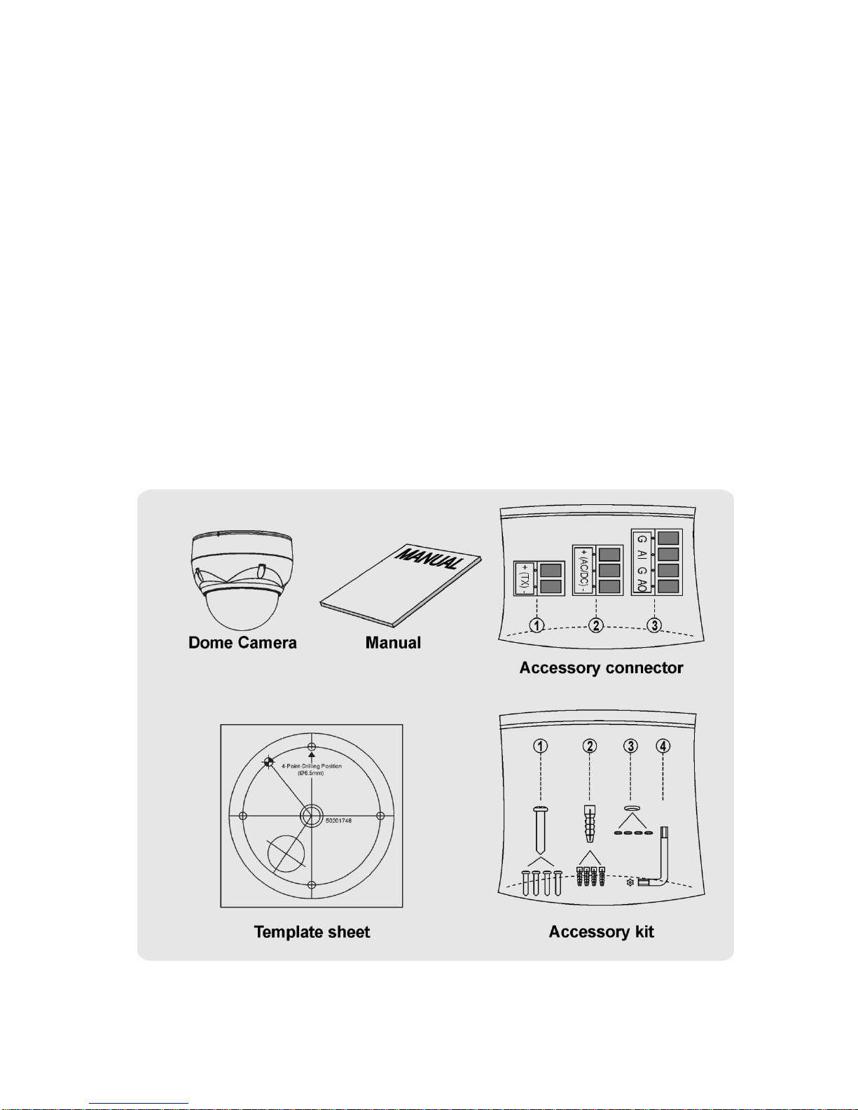
2.1 Package Contents
VK2-600PTZ is design to be a compact, ,vandal resistant dome camera.
The housing is constructed of aluminum, steel and plastic. The housing is designed to be
mounted both wall and ceiling type.
The housing meets the Protection Classification IP66 standards for dust and moisture resistance.
* Dome Camera ................................................................1
* Software / Manual CD ...................................................1
* Template sheet ..............................................................1
* Accessory kit .................................................................1
1) Mounting screws (PH6 x 35.0) ..........(4)
2) Plastic anchors ..................................(4)
3) O-Rings .............................................(4)
4) Torx wrench .......................................(1)
* Accessory connector ....................................................1
1) 2Pin Terminal Block ...........................(1)
2) 3Pin Terminal Block ...........................(1)
3) 6Pin Terminal Block ...........................(1)
3
VK2-600PTZ User manual
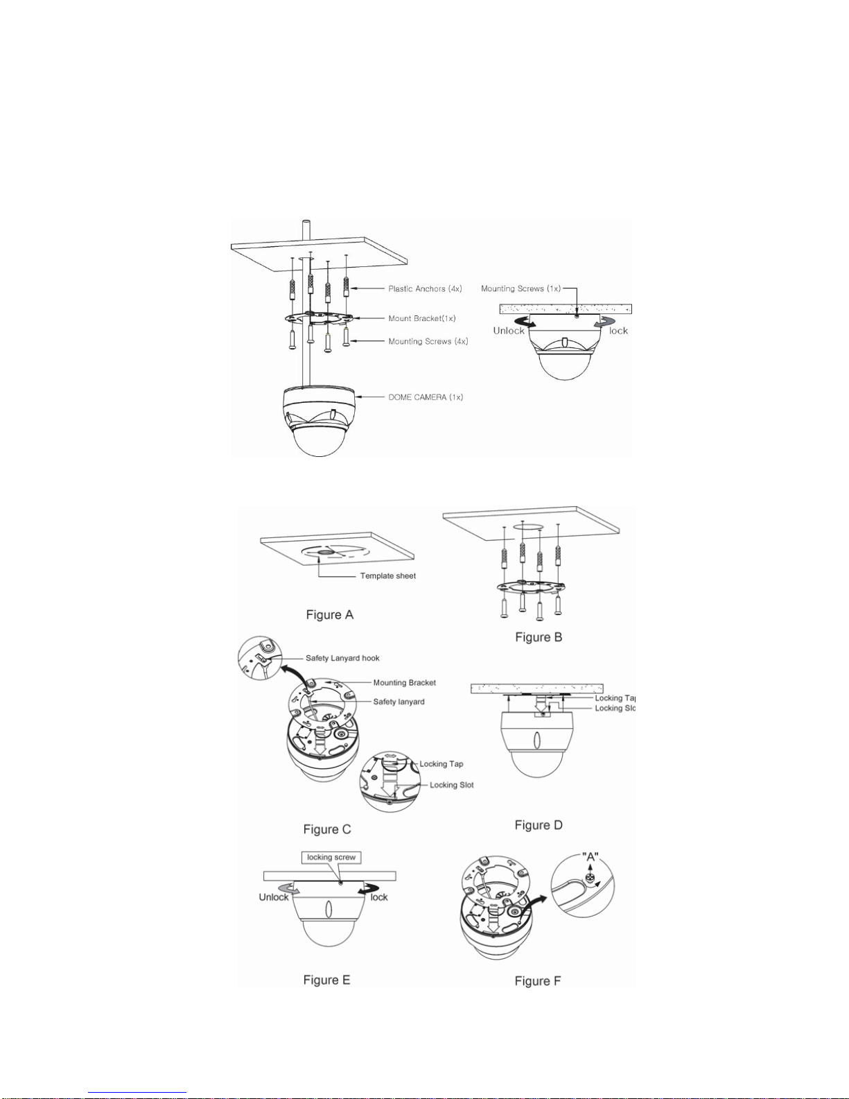
2.2 Installation
VK2-600PTZ is for use in surface mounting applications and the mounting surface
should be capable of supporting loads up to 3.5lb (1.6kg).
VK2-600PTZ‘s base should be attached to a structural object, such as hard wood, wall
stud or ceiling rafter that supports the weight of VK2-600PTZ.

4
VK2-600PTZ User manual
CAUTION: Before installing the bracket to surface, adjust the four mounting screws "A"
on the base of the dome camera to best match the mounting bracket locked position.
Unscrew the locking screw on the side of the dome's base and fit the tab of the mounting
bracket into the locking slot. Screws "A" should not be too tight or too loose when the
dome is in the locked position. After setting the proper positions of screws "A" remove
the mounting bracket and install it to the proper surface. If it is too difficult to lock the
dome in position after the mounting bracket has been installed readjust the screws "A" by
unscrewing them a small amount and try to install dome camera again.
5
VK2-600PTZ User manual
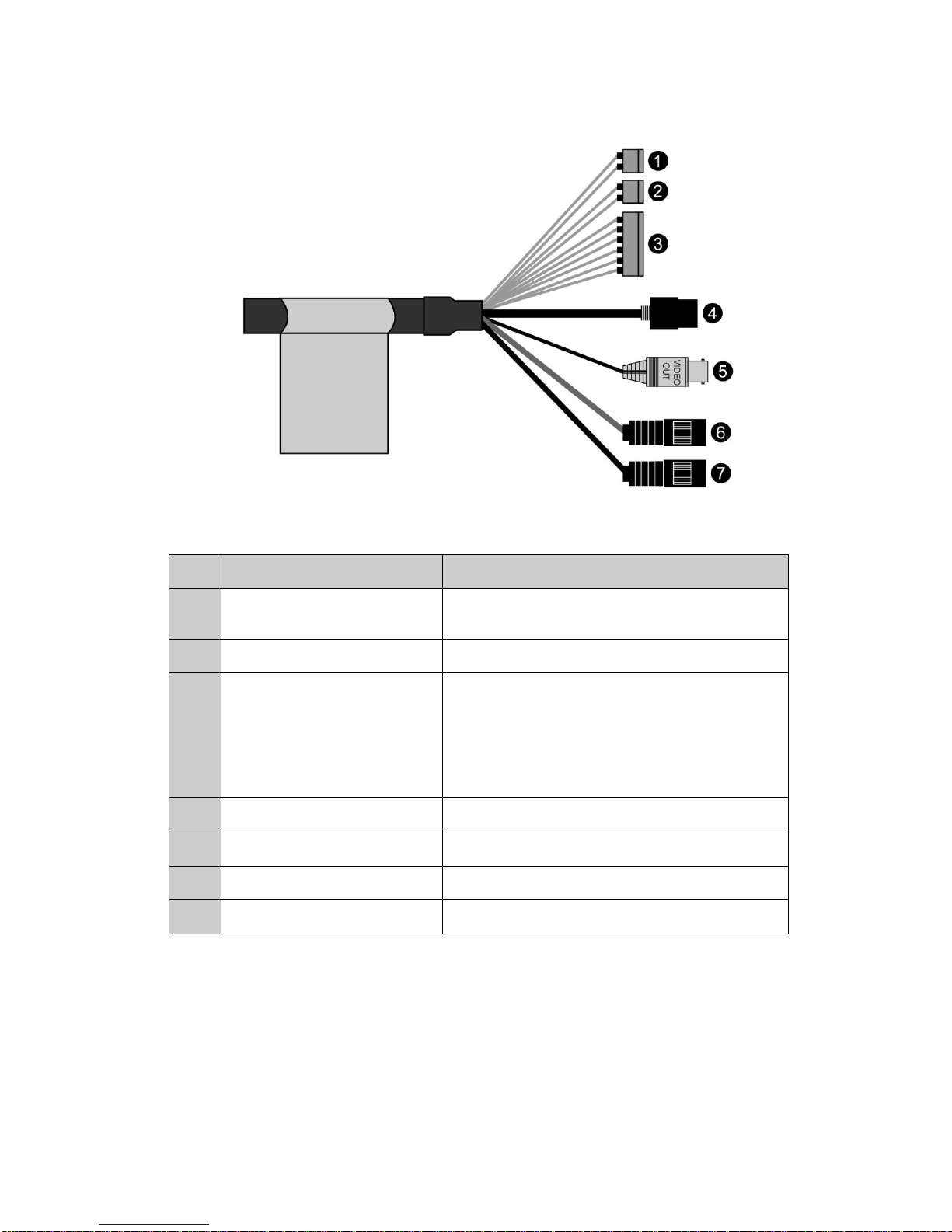
2.3 Basic Configuration of Dome Camera System
No.
Wire Color
Description
1
Red: 12V DC+
White: 12V DC-
Main Power: 2pin terminal
2
Pink, Brown
Heater Power(Option): 3pin terminal
3
Black: GND
Gray: Alarm Input
Yellow: GND
Black&White: Alarm Output
Green: RS485+
Blue: RS485-
Alarm Input/Output, RS485: 6pin terminal
4
Black
Ethernet: RJ45 Modular Jack
5
Yellow
Video Composite Output: BNC Jack
6
Red
Audio line output: RCA Jack
7
White
Audio line input: RCA Jack
VK2-600PTZ must be installed by qualified service personnel in accordance with all local
electrical and building codes.

6
VK2-600PTZ User manual
2.4 Connections
• Connecting to the RJ-45
Connect a standard RJ-45 cable to the network port of VK2-600PTZ. Generally a cross-over
cable is used for directly connection to PC, while a direct cable is used for connection to a hub.
• Connecting Alarms
AI (Alarm In)
You can use external devices to signal VK2-600PTZ to react on events. Mechanical or electrical
switches can be wired to the AI (Alarm In) and G (Ground) connectors.
See ―4.5.4 Event > 1) Event-In > Alarm In‖ for configuring alarm input.
G (Ground)
NOTE: All the connectors marked G or GND are common.
Connect the ground side of the alarm input and/or alarm output to the G (Ground) connector.
AO (Alarm Output)
VK2-600PTZ can activate external devices such as buzzers or lights. Connect the device to the
AO (Alarm Out) and G (Ground) connectors.
See ―4.5.4 Event > 2) Event-Out > Alarm Out‖ for configuring alarm output.
• Connecting to the RS485
VK2-600PTZ can be controlled remotely by an external device or control system, such as a
control keyboard, using RS485 half-duplex serial communications signals.
• Connecting Video out connector
Connect the video out (BNC) connector to the monitor or video input.
• Connecting the Power
Connect the power of DC12V 1.2A for VK2-600PTZ.
When using a DC 12V adapter, connector the positive(+) pole to the ‗+‘ position and the
negative(-) pole to the ‗-‗ position.
Use satisfy clause 2.5 of IEC60950-1/UL60950-1 or Certified/Listed Class 2 power source only.
7
VK2-600PTZ User manual
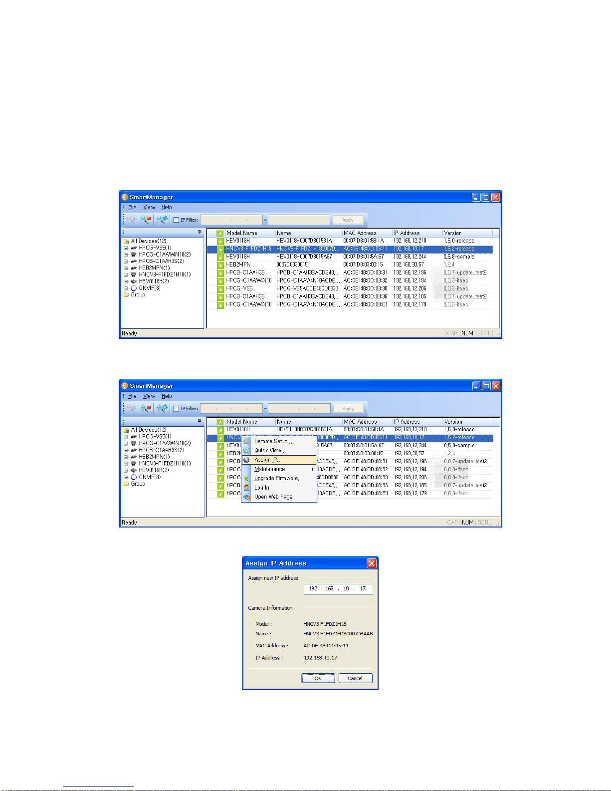
2.5 IP Assignment
When VK2-600PTZ, encoder or decoder is first connected to the network it has no IP address.
So, it is necessary to allocate an IP address to the device with the ―SmartManager‖ utility on the
CD.
1. Connect VK2-600PTZ / device to the network and power up.
2. Start SmartManager utility (All programs > NautilusClient16 > SmartManager), the main
window will be displayed, after a short while any network devices connected to the network
will be displayed in the list.
3. Select VK2-600PTZ on the list and click right button of the mouse.
You can see the pop-up menu as below.
4. Select Assign IP Address. You can see Assign IP window. Enter the required IP address.
Note: For more information, refer to the Smart Manger User‘s Manual.
8
VK2-600PTZ User manual
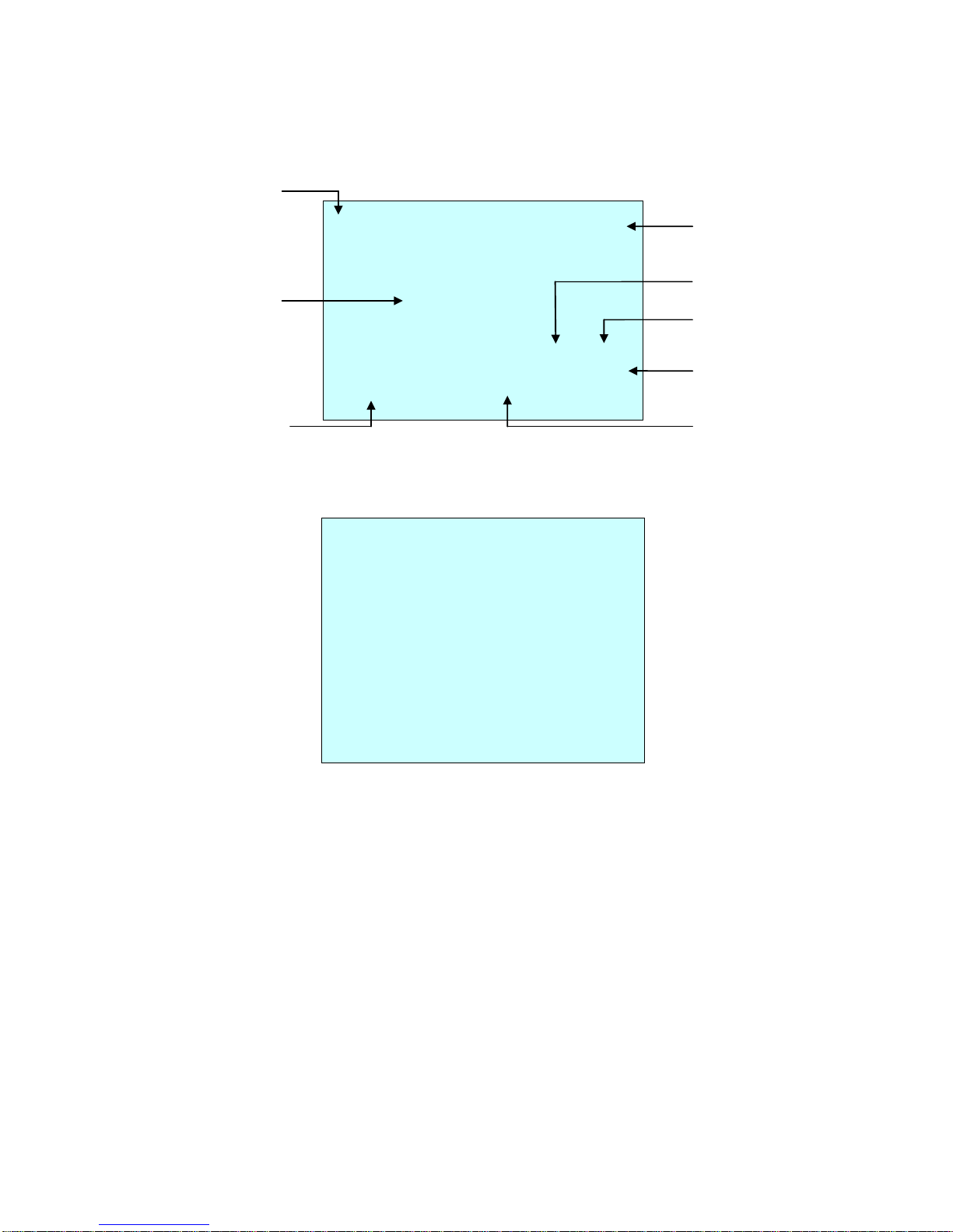
2.6 Getting Started
Once installed apply power to VK2-600PTZ. It will start a configuration sequence.
OSD Position
The dome can move the OSD position in the OSD position setup.
(AREA TITLE) (AF AE)
(FUNC TITLE )
(CTRL KEY TO MOVE)
SAVE AND EXIT(ESC TO CANCEL)
(ALARM MESSAGE) (DOME ID…)
(ANGLE…)
OSD Position Setup
001 AF AE
EMPTY DATA
DOMEID:0001
ALARM:1 W→360.0,090.0
INFORMATION
DISPLAY
FUNCTION
UNDER RUNNING
ALARM DISPLAY
CAMERA TITLE
CAMERA ID
VIEW DIRECTION
PAN & TILT ANGLE
PRESET TITLE
AREA TITLE
STATUS of
FOCUS and AE
9
VK2-600PTZ User manual
Chapter 3 — Operation by Web Browser
The VK2-600PTZ can be used with Windows operating system and browsers.
The recommended browsers are Internet Explorer, Safari, Firefox, Opera and Google Chrome
with Windows.
Note: To view streaming video in Microsoft Internet Explorer, set your browser to allow ActiveX
controls.
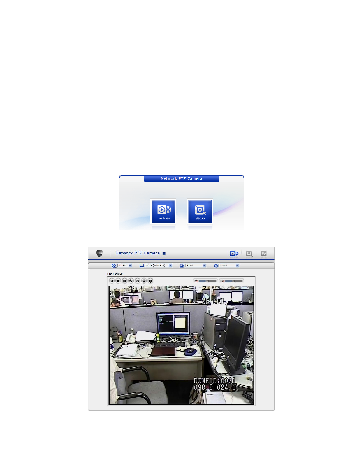
3.1 Access from a browser
1) Start a browser (Internet Explorer).
2) Enter the IP address or host name of the network camera in the Location/Address field of
your browser.
3) You can see a starting page. Click Live View or Setup to enter web page.
4) The encoder‘s Live View page appears in your browser.
10
VK2-600PTZ User manual
3.2 Access from the internet
Access from the internet once connected, the network camera is accessible on your local
network (LAN). To access the video encoder from the Internet you must configure your
broadband router to allow incoming data traffic to the video encoder. To do this, enable the NAT
traversal feature, which will attempt to automatically configure the router to allow access to the
video encoder. This is enabled from Setup > System > Network > NAT.
For more information, please see NAT traversal (port mapping) for IPv4, on ―4.5.5 System > 4)
Network > NAT traversal‖.
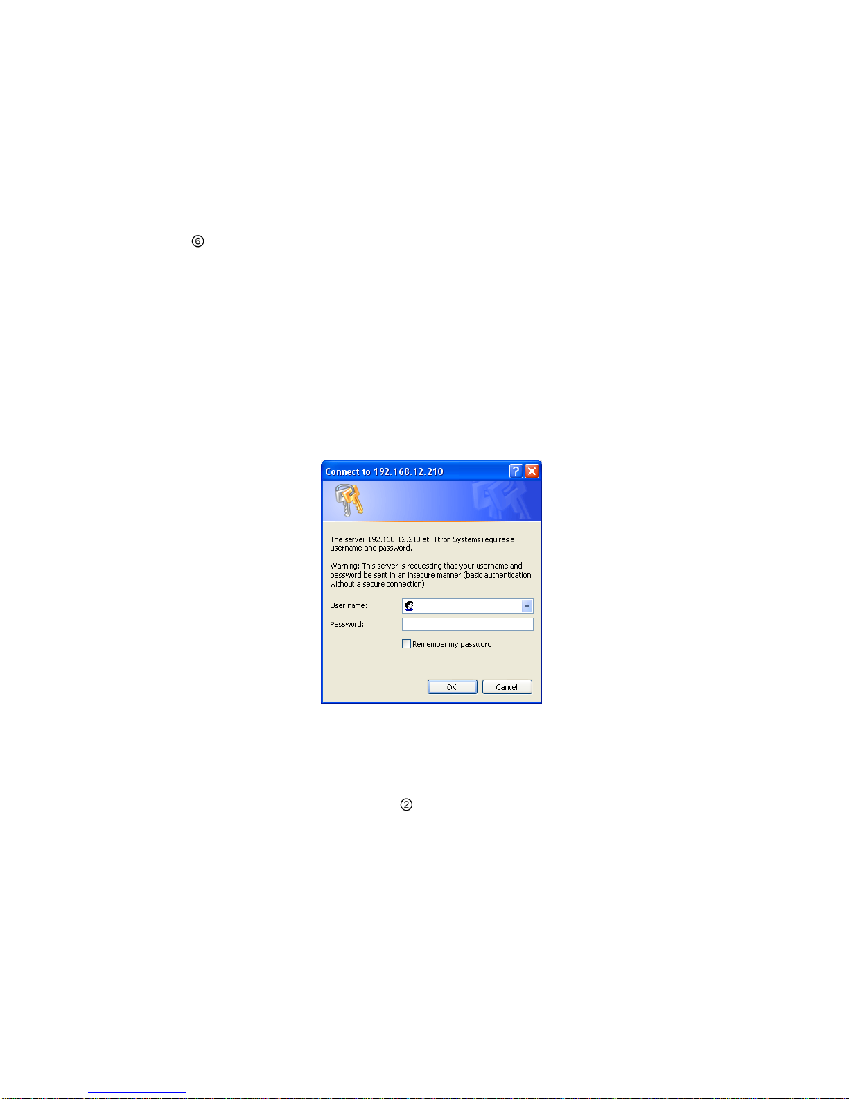
3.3 Setting the admin password over a secure connection
To gain access to the product, the password for the default administrator user must be set. This
is done in the ―Admin Password‖ dialog, which is displayed when the network camera is
accessed for the setup at the first time. Enter your admin name and password, set by the
administrator.
Note: The default administrator username and password is ―admin‖. If the password is lost, the
network camera must be reset to the factory default settings.
See ―4.8 Resetting to the factory default settings‖ for more details.
To prevent network eavesdropping when setting the admin password, this can be done via an
encrypted HTTPS connection, which requires an HTTPS certificate (see note below).
To set the password via a standard HTTP connection, enter it directly in the first dialog shown
below. To set the password via an encrypted HTTPS connection, see Setup > System > Security
> HTTPS, on ―4.5.5 System > 2) Security > HTTPS‖.
Note: HTTPS (Hypertext Transfer Protocol over SSL) is a protocol used to encrypt the traffic
between web browsers and servers. The HTTPS certificate controls the encrypted
exchange of information.
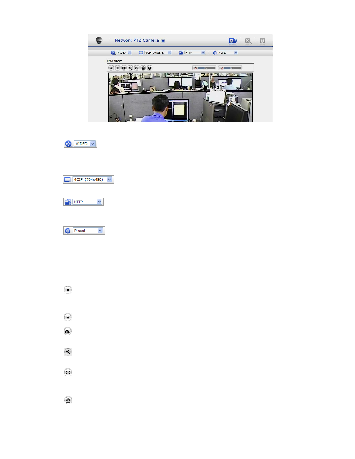
3.4 Live View Page
The live view page comes in seven screen modes like 704x576(480), 704x288(240),
352x288(240), 176x144(120), 640x480, 320x240 and 160x120. Users are allowed to select the
most suitable one out of those modes. Please, adjust the mode in accordance with your PC
specifications and monitoring purposes.
11
VK2-600PTZ User manual
1) General controls
The video drop-down list allows you to select a customized or pre-
programmed video stream on the live view page. Stream profiles are
configured under Setup > Basic Configuration > Video & Image.
See ―4.5.1 Basic Configuration‖ for more information.
The resolution drop-down list allows you to select the most suitable one
out of video resolutions to be displayed on live view page.
The protocol drop-down list allows you to select which combination of
protocols and methods to use depends on your viewing requirements, and
on the properties of your network.
The preset drop-down list allows you to select the preset number for the
PTZ camera being used. This icon is inactivated if the PTZ settings are not
set.
2) Control toolbar
The live viewer toolbar is available in the web browser page only. It displays the following
buttons:
The Stop button stops the video stream being played. Pressing the key again toggles
the start and stop. The Start button connects to the network camera or start playing a
video stream.
The Pause button pause the video stream being played.
The Snapshot button takes a snapshot of the current image. The location where the
image is saved can be specified.
The digital zoom activates a zoom-in or zoom-out function for video image on the live
screen.
The Full Screen button causes the video image to fill the entire screen area. No other
windows will be visible. Press the 'Esc' button on the computer keyboard to cancel full
screen view.
The Manual Trigger button activates a pop-up window to manually start or stop the
event.

12
VK2-600PTZ User manual
The Camera Menu button activates a pop-up window for camera menu control.
The PTZ button activates a pop-up window for Pan, Tilt and Zoom control.
Use this scale to control the volume of the speakers.
Use this scale to control the volume of the microphone.
Use this scale to control the volume of the speakers and microphones.
3) Camera Menu controls
If the network camera has been appropriately configured, the Live View page displays the
controls available for the OSD menu.
For more information, please see ―Chapter 3 — Program and Operation‖.
4) Pan/Tilt/Zoom controls
If the network camera has been appropriately configured, the Live View page displays the
controls available for the PTZ (Pan Tilt Zoom) or PT device installed. The administrator can
enable/disable the controls for specified users.
Please see ―4.6 PTZ Control‖ for more information.
5) Video and Audio Streams
The network camera provides several images and video stream formats. Your requirements
and the properties of your network will determine the type you use.
The Live View page in the network camera provides access to H.264, MPEG-4 and Motion
JPEG video streams, and to the list of available video streams. Other applications and
clients can also access these video streams/images directly, without going via the Live View
page.
3.5 Network Camera Setup
This section describes how to configure the network camera, and is intended for product
Administrators, who have unrestricted access to all the Setup tools; and Operators, who have
access to the settings for Basic, Live View, Video & Image, Audio, Event, and System
Configuration.
You can configure the network camera by clicking Setup in the top right-hand corner of the Live
View page. Click on this page to access the online help that explains the setup tools.
13
VK2-600PTZ User manual
When accessing the network camera for the first time, the ―Admin Password‖ dialog appears.
Enter your admin name and password, set by the administrator.
Note: If the password is lost, the network camera must be reset to the factory default settings.
See ―4.8 Resetting to the Factory Default Settings‖.
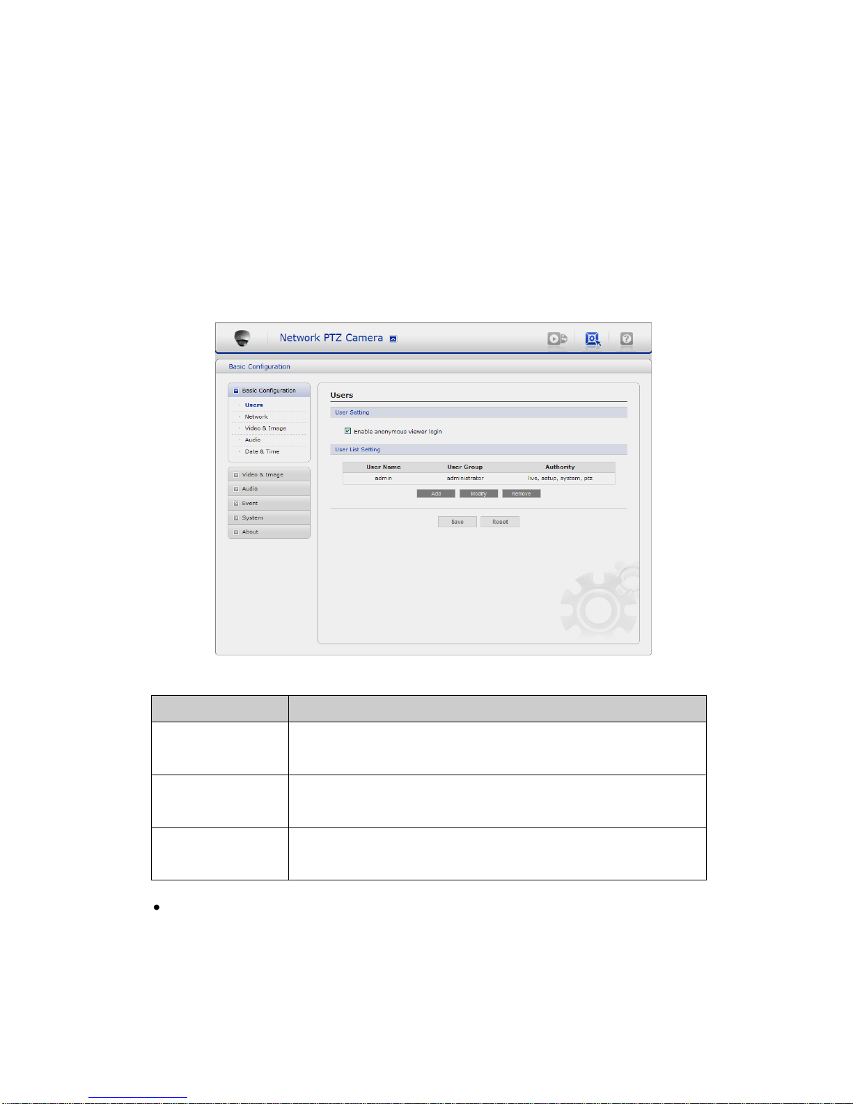
3.5.1 Basic Configuration
1) Users
User access control is enabled by default. An administrator can set up other users, by giving
these user names and passwords. It is also possible to allow anonymous viewer login, which
means that anybody may access the Live View page, as described below:
The user list displays the authorized users and user groups (levels):
User Group
Authority
Guest
Provides the lowest level of access, which only allows access
to the Live View page.
Operator
An operator can view the Live View page, create and modify
events, and adjust certain other settings. Operators have no
access to System Options.
Administrator
An administrator has unrestricted access to the Setup tools
and can determine the registration of all other users.
Enable anonymous viewer login: Check the box to use the webcasting features.
Refer to ―4.5.2 Video & Image‖ for more details.
14
VK2-600PTZ User manual
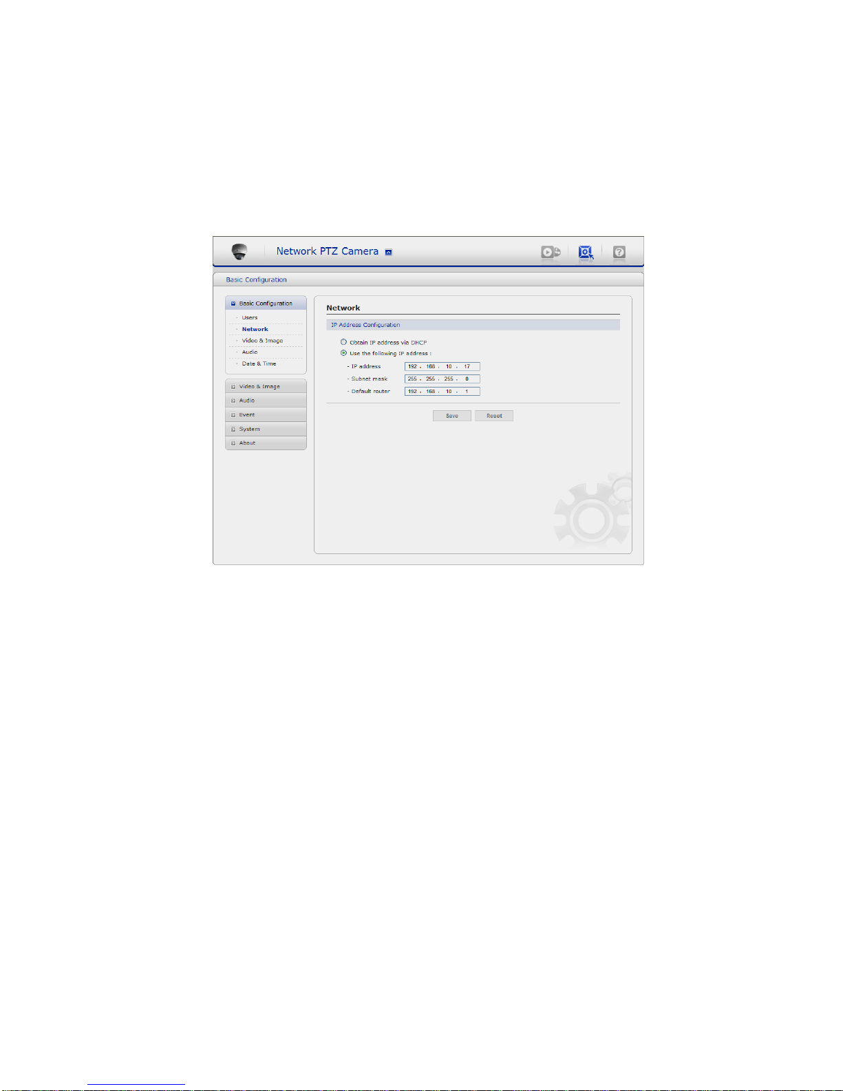
2) Network
The network camera support both IP version 4 and IP version 6. Both versions may be
enabled simultaneously, and at least one version must always be enabled. When using IPv4,
the IP address for the video encoder can be set automatically via DHCP, or a static IP
address can be set manually. If IPv6 is enabled, the video encoders receive an IP address
according to the configuration in the network router. There is also the option of using the
Internet Dynamic DNS Service. For more information on setting the network, please see
Setup > System > Network, on ―4.5.5 System > 4) Network‖.
• Obtain IP address via DHCP: Dynamic Host Configuration Protocol (DHCP) is a protocol
that lets network administrators centrally manage and automate the assignment of IP
addresses on a network. DHCP is enabled by default. Although a DHCP server is mostly
used to set an IP address dynamically, it is also possible to use it to set a static, known IP
address for a particular MAC address.
• Use the following IP address: To use a static IP address for the network camera, check
the radio button and then make the following settings:
- IP address - Specify a unique IP address for your network camera.
- Subnet mask - Specify the mask for the subnet the network camera is located on.
- Default router - Specify the IP address of the default router (gateway) used for
connecting devices attached to different networks and network segments.
Notes:
1. DHCP should only be enabled if using dynamic IP address notification, or if your DHCP
server can update a DNS server, which then allows you to access the network camera by
name (host name). If DHCP is enabled and you cannot access the unit, you may have to
reset it to the factory default settings and then perform the installation again.
2. The ARP/Ping service is automatically disabled two minutes after the unit is started,
or as soon as an IP address is set.
3. Pinging the unit is still possible when this service is disabled.
15
VK2-600PTZ User manual
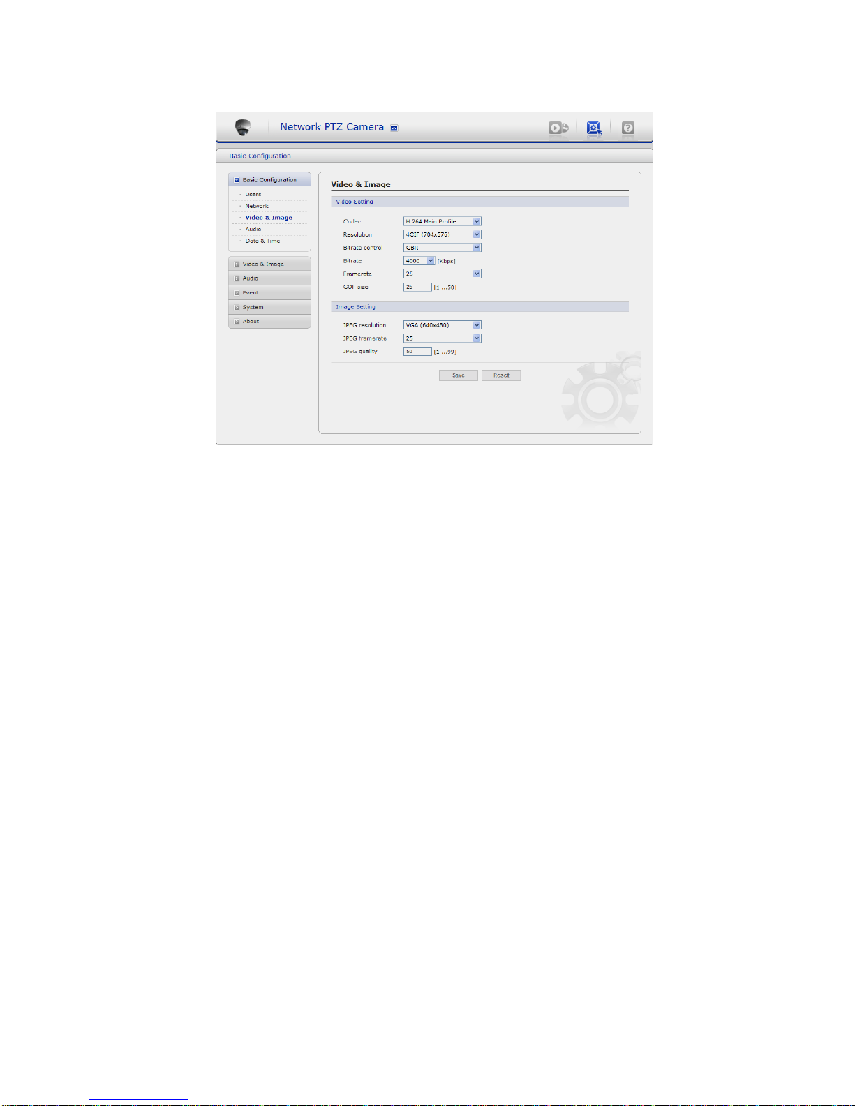
3) Video & Image
• Video Setting:
- Codec: The codec settings are separated into MPEG4 and H.264.
H.264 is also known as MPEG-4 Part 10. This is the new generation compression
standard for digital video.
This function offers higher video resolution than Motion JPEG or MPEG-4 at the same
bit rate and bandwidth, or the same quality video at a lower bit rate.
- Profile: There are 4 pre-programmed stream profiles available for quick set-up.
Choose the form of video encoding you wish to use from the drop-down list:
* H.264 MP(Main Profile): Primarily for low-cost applications that requires additional
error robustness, this profile is used rarely in videoconferencing and mobile
applications, it does add additional error resilience tools to the Constrained Baseline
Profile. The importance of this profile is fading after the Constrained Baseline Profile
has been defined.
* H.264 BP(Base Profile): Originally intended as the mainstream consumer profile for
broadcast and storage applications, the importance of this profile faded when the
High profile was developed for those applications.
* MPEG4 SP(Simple Profile): Mostly aimed for use in situations where low bit rate and
low resolution are mandated by other conditions of the applications, like network
bandwidth, device size etc.
* MPEG4 ASP(Advanced Simple Profile): Its notable technical features relative to the
Simple Profile, which is roughly similar to H.263, including "MPEG"-style quantization,
interlaced video, B pictures (also known as B Frames), Quarter Pixel motion
compensation (Qpel), Global motion compensation (GMC).
- Resolution: It enables users to determine a basic screen size when having an access
through the Web Browser or PC program. The screen size control comes in seven
modes like 4CIF(704x576(480)), 2CIF(704x288(240)), CIF(352x288(240)),
QCIF(176x144(120)), VGA(640x480), QVGA(320x240), and QQVGA(160x120). Users
can reset the selected screen size anytime while monitoring the screen on a real-time
basis.

16
VK2-600PTZ User manual
- Bitrate control: Limiting the maximum bit rate helps control the bandwidth used by the
H.264 or MPEG-4 video stream. Leaving the Maximum bit rate as unlimited maintains
consistently good image quality but increases bandwidth usage when there is more
activity in the image. Limiting the bit rate to a defined value prevents excessive
bandwidth usage, but images are lost when the limit is exceeded.
Note that the maximum bit rate can be used for both variable and constant bit rates.
The bit rate can be set as Variable Bit Rate (VBR) or Constant Bit Rate (CBR). VBR
adjusts the bit rate according to the image complexity, using up bandwidth for increased
activity in the image, and less for lower activity in the monitored area.
CBR allows you to set a fixed target bitrate that consumes a predictable amount of
bandwidth. As the bit rate would usually need to increase for increased image activity,
but in this case cannot, the frame rate and image quality are affected negatively. To
partly compensate for this, it is possible to prioritize either the frame rate or the image
quality whenever the bit rate needs to be increased. Not setting a priority means the
frame rate and image quality are equally affected.
- Compression: When it is necessary to adjust a smooth transmission status according to
network situations, users can increase the compressibility to carry out the network
transmission stably. On the other hand, when it is necessary to maintain a detailed
monitoring screen by enhancing the image quality, users can do so by decreasing the
compressibility. In ease case, please adjust this function according to the network status
and monitoring purposes. The default is 2000(Kbps).
- Frame rate: Upon the real-time play, users should select a frame refresh rate per second.
If the rate is high, the image will become smooth. On the other hand, if the rate is low,
the image will not be natural but it can reduce a network load.
- GOP size: Select the GOP(Group of Picture) size. If users want to have a high quality of
fast image one by one, please decrease the value. For the purpose of general
monitoring, please do not change a basic value. Such act may cause a problem to the
system performance. For the details of GOP setting, please contact the service center.
• Image Setting: Sometimes the image size is large due to low light or complex scenery.
Adjusting the frame rate and quality helps to control the bandwidth and storage used by
the Motion JPEG video stream in these situations. Limiting the frame rate and quality
optimizes bandwidth and storage usage, but may give poor image quality. To prevent
increased bandwidth and storage usage, the Resolution, Frame rate, and Frame Quality
should be set to an optimal value.
- JPEG resolution: Same as the video settings.
- JPEG frame rate: Same as the video settings.
- JPEG quality: Select the picture quality. If users want to have a high quality of fast
image one by one, please decrease the value. For the purpose of general monitoring,
please do not change a basic value. Such act may cause a problem to the system
performance.
When satisfied with the settings, click Save, or click Reset to revert to previously saved
settings.
17
VK2-600PTZ User manual
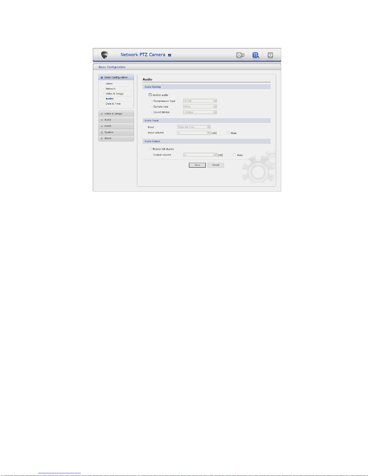
4) Audio
The network camera can transmit audio to other clients using an external microphone and
can play audio received from other clients by attaching a speaker. The Setup page has an
additional menu item called Audio, which allows different audio configurations, such as, full
duplex, and simplex.
• Audio Setting:
- Enable audio: Check the box to enable audio in the video stream.
- Compression type: Select the desired audio Compression format, G726.
- Sample rate: Select the required Sample rate (number of times per second the sound is
sampled). The higher the sample rate, the better the audio quality and the greater the
bandwidth required.
- Sound bitrate: Depending on the selected encoding, set the desired audio quality
(bitrate). The settings affect the available bandwidth and the required audio quality.
• Audio Input:
Audio from an external line source can be connected to the RCA Jack I/O of the network
camera.
- Input volume: If there are problems with the sound input being too low or high, it is
possible to adjust the input gain for the microphone attached to the network camera.
• Audio Output:
- Enable full duplex: Check the box to enable Full Duplex mode. It means that you can
transmit and receive audio (talk and listen) at the same time, without having to use any
of the controls. This is just like having a telephone conversation.
This mode requires that the client PC has a sound card with support for full-duplex
audio.
Uncheck the box enable Simplex mode. The simplex mode only transmits audio from
the network camera to any web client. It does not receive audio from other web clients.
18
VK2-600PTZ User manual
- Output volume: If the sound from the speaker is too low or high it is possible to adjust
the output gain for the active speaker attached to the network camera.
When satisfied with the settings, click Save, or click Reset to revert to previously saved
settings.
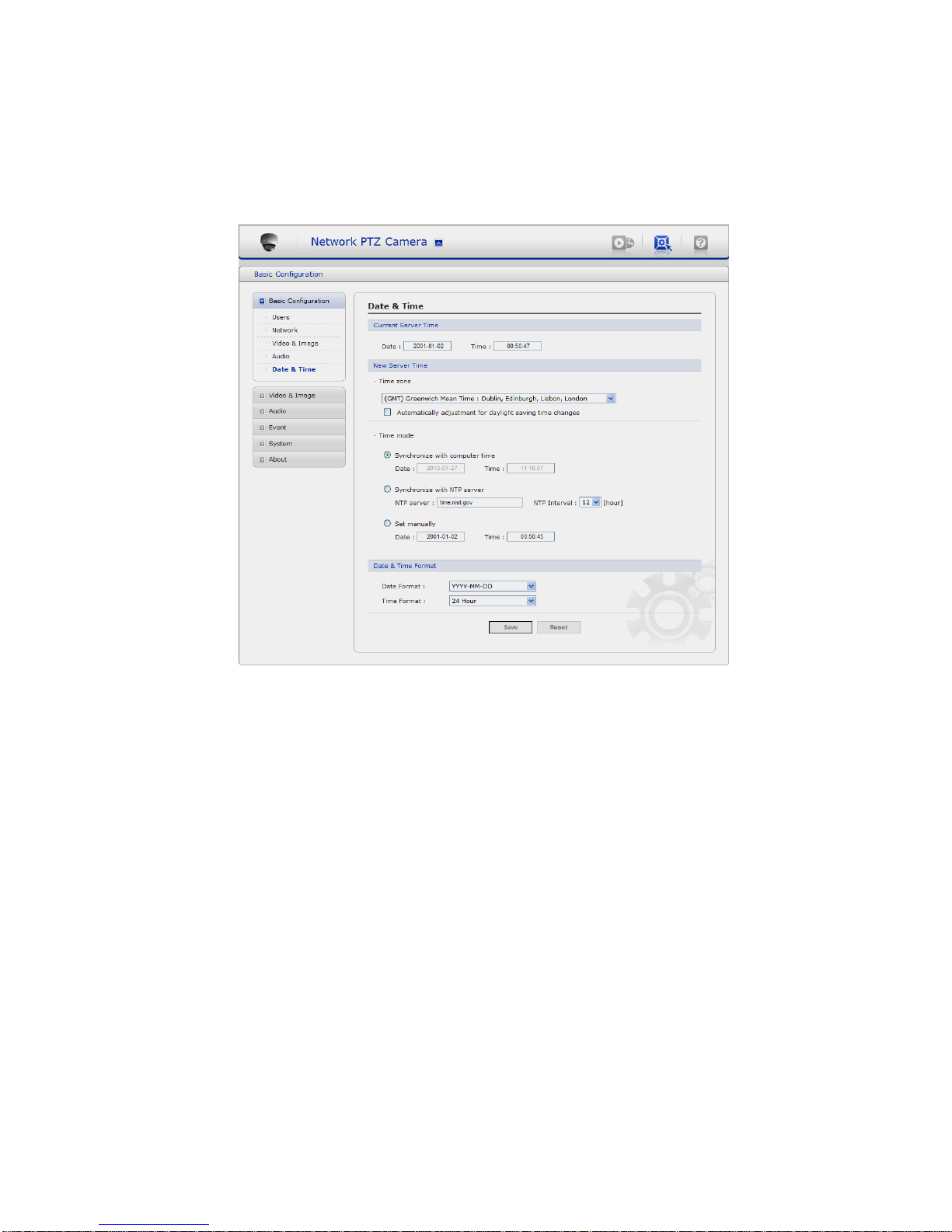
5) Date & Time
• Current Server Time:
It displays the current date and time (24h clock). The time can be displayed in 12h clock
format in the overlay (see below).
• New Server Time:
Select your time zone from the drop-down list. If you want the server clock to automatically
adjust for daylight savings time, select the ―Automatically adjustment for daylight saving
time changes‖.
From the Time Mode section, select the preferred method to use for setting the time:
- Synchronize with computer time: sets the time from the clock on your computer.
- Synchronize with NTP Server: the video encoder will obtain the time from an NTP
server every 60 minutes.
- Set manually: this option allows you to manually set the time and date.
19
VK2-600PTZ User manual
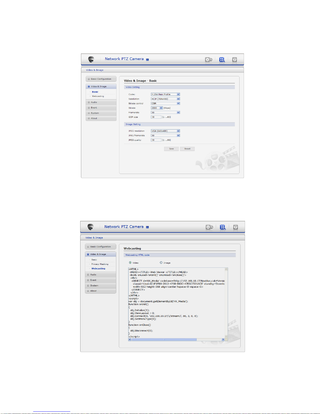
3.5.2 Video & Image
1) Basic
Refer to ―4.5.1 Basic Configuration > 3) Video & Image‖ for more details.
2) Webcasting – Channel1
The network camera can stream live video to a website. Copy the HTML code generated on
the screen and paste it in page code of the website you want to display live video.
Note: To use webcasting service, the Enable Anonymous viewer login option must be
checked. Refer to ―3.5.1 Basic Configuration > 1) Users‖ for more details.
 Loading...