

Vista VK2-540VRD, VIP2 VK2-540VRD User Manual
VK2-540VRD
User Manual

2
3
WARNING
TO REDUCE THE RISK OF FIRE OR ELECTRIC SHOCK, DO NOT EXPOSE THIS
PROCUCT TO RAIN OR MOISTURE. DO NOT INSERT ANY METALLIC OBJECT
THROUGH THE VENTILATION GRILLS OR OTHER OPENNINGS ON THE EQUIPMENT.
CAUTION
The lightning flash with arrowhead symbol, within an equilateral triangle, is intended to
alert the user to the presence of uninsulated "dangerous voltage" within the product’s
enclosure that may be of sufficient magnitude to constitute a risk of electric shock.
The exclamation point within an equilateral triangle is intended to alert the user to the
presence of important operating and maintenance (servicing) instructions in the literature
accompanying the appliance.
4
FCC COMPLIANCE STATEMENT
INFORMATION TO THE USER: THIS EQUIPMENT HAS BEEN TESTED AND FOUND
TO COMPLY WITH THE LIMITS FOR A CLASS A DIGITAL DEVICE, PURSUANT TO PART 15 OF
THE FCC RULES. THESE LIMITS ARE DESIGNED TO PROVIDE REASONABLE PROTECTION
AGAINST HARMFUL INTERFERENCE WHEN THE EQUIPMENT IS OPERATED IN A
COMMERCIAL ENVIRONMENT. THIS EQUIPMENT GENERATES, USES, AND CAN RADIATE
RADIO FREQUENCY ENERGY AND IF NOT INSTALLED AND USED IN ACCORDANCE WITH
THE INSTRUCTION MANUAL, MAY CAUSE HARMFUL INTERFERENCE TO RADIO
COMMUNICATIONS.
OPERATION OF THIS EQUIPMENT IN A RESIDENTIAL AREA IS LIKELY TO CAUSE HARMFUL
INTERFERENCE IN WHICH CASE THE USER WILL BE REQUIRED TO CORRECT THE
INTERFERENCE AT HIS OWN EXPENSE.
CAUTION: CHANGES OR MODIFICATIONS NOT EXPRESSLY APPROVED BY THE PARTY
RESPONSIBLE FOR COMPLIANCE COULD VOID THE USER'S AUTHORITY TO OPERATE
THE EQUIPMENT.
THIS CLASS A DIGITAL APPARATUS COMPLIES WITH CANADIAN ICES-003.
CET APPAREIL NUMERIQUE DE LA CLASSE A SET CONFORME A LA NORME NMB-003 DU
CANADA.
WARNING: This is a Class A product. In a domestic environment this product may cause radio
interference in which case the user may be required to take adequate measures.
CE COMPLIANCE STATEMENT

5
IMPORTANT SAFETY INSTRUCTIONS
1. Read these instructions.
2. Keep these instructions.
3. Heed all warnings.
4. Follow all instructions.
5. Do not use this apparatus near water.
6. Clean only with dry cloth.
7. Do not block any ventilation openings. Install in accordance with the manufacturer’s
instructions.
8. Do not install near any heat sources such as radiators, heat registers, stoves, or
other apparatus (including amplifiers) that produce heat.
9. Do not defeat the safety purpose of the polarized or grounding-type plug. A
polarized plug has two blades with one wider than the other. A grounding type plug
has two blades and a third grounding prong. The wide blade or the third prong are
provided for your safety. If the provided plug does not fit into your outlet, consult an
electrician for replacement of the obsolete outlet.
10. Protect the power cord from being walked on or pinched particularly at plugs,
convenience receptacles, and the point where they exit from the apparatus.
11. Only use attachments/accessories specified by the manufacturer.
12. Use only with the cart, stand, tripod, bracket, or table
specified by the manufacturer, or sold with the apparatus.
When a cart is used, use caution when moving the
cart/apparatus combination to avoid injury from tip-over.
13. Unplug this apparatus during lightning storms or when
unused for long periods of time.
14. Refer all servicing to qualified service personnel. Servicing is
required when the apparatus has been damaged in any way,
such as power-supply cord or plug is damaged, liquid has been moisture, does not
operate normally, or has been dropped.
15. CAUTION – THESE SERVICING INSTRUCTIONS ARE FOR USE BY
QUALIFIED SERVICE PERSONNEL ONLY. TO REDUCE THE RISK OF
ELECTRIC SHOCK DO NOT PERFORM ANY SERVICING OTHER THAN
THAT CONTAINED IN THE OPERATING INSTRUCTIONS UNLESS YOU
QRE QUALIFIED TO DO SO.
16. Use satisfy clause 2.5 of IEC60950-1/UL60950-1 or Certified/Listed
Class 2 power source only.
17. ITE is to be connected only to PoE networks without routing to the outside
plant.

6
Table of Contents
1. Product Description…………………………………………………………………………………………………7
2. Installation……………………………………………………..........................…………..……………….9
3. Operation…………………………………………………………………………………………………………….14
3.1 Access from a browser …………………………………………………………………………………..14
3.2 Access from the internet ………………………………………………………………………………..15
3.3 Setting the admin password over a secure connection…………………………….…….…15
3.4 Live View Page ………………………………………………………………………………………………16
3.5 Camera Setup (Analog)……………………………………………………………………………….….18
3.5.1 Settings…………………………………………………………………………………………………..18
3.5.2 Lens Adjustment (Optical Vari-focal Lens)…………………………………………………..24
3.6 Network Camera Setup………………………………………………………………………………...25
3.6.1 Basic Configuration…………………………………………………………………….…………...26
3.6.1.1 Users…………………………………………………………………………………….………...26
3.6.1.2 Network……………………………………………………………………………….…………...27
3.6.1.3 Video & Image..……………………………………………….……………………………...28
3.6.1.4 Audio..…..……………………………………………………….…………………………….....31
3.6.1.5 Date & Time..……………………………………………………………………….………...32
3.6.2 Video & Image..……………..……………………………………………………………………....33
3.6.3 Audio..……………………………….………………………………………………………………....36
3.6.4 Event………………………………………………………………………………………………………37
3.6.4.1 Event-In…………………………………………………………………………………………….37
3.6.4.2 Event-Out………………………………………………………………………………………….42
3.6.4.3 Event Map…………………………………………………………………………………………49
3.6.5 System……………………………………………………………………………………….………...50
3.6.5.1 Information………………………………………………………….…………………………...50
3.6.5.2 Security..…………………………………………………………….…………………………...51
3.6.5.3 Date & Time..…………………………………………………………………….…………...54
3.6.5.4 Network..……………………………………………………………………….……………....55
3.6.5.5 Language..……………….…………………………………….……………………………....62
3.6.5.6 Maintenance..……………..………………………………….…..........................…....63
3.6.5.7 Support............……………………………………….........................….…………....64
3.7 About……………..………………………..…………………………………………………….…………....64
3.8 camera Menu Control.……….……..…………………………………………………….…………....65
3.9 Help…………………………………………….……………………………………………………………....66
3.10 Resetting to the factory default settings……………….……………………………………....67
4. Appendix ……………………………………………………………..……………………………………….……68
4.1. Troubleshooting.…………………………..……………………………………………………….……68
4.2. Preventive Maintenance..………………………..........................….…………………….……69
4.3. Product Specification…..………………………………………………………………..….….....……70
7
1. Product Description
This manual applies to the VIP2 Camera – VK2-540VRD.
The VK2-540VRD vandal resistant dome is a Hybrid analogue and IP camera. It has a
standard composite BNC out put allowing it to be connected via coax to a traditional coax
based CCTV system, as well as being connected to an IP based system.
The VK2-540VRD comes supplied with its own viewing software which allows the user to
View, record and configure the camera. Viewing and configuration can also be carried out
via a web browser such as Internet Explorer.
The camera can transmit real time full frame rate video in H.264, MJPEG or MPEG4
compression formats.
The alarm input and alarm output can be used to connect various third party devices, such
as, door sensors and alarm bells.
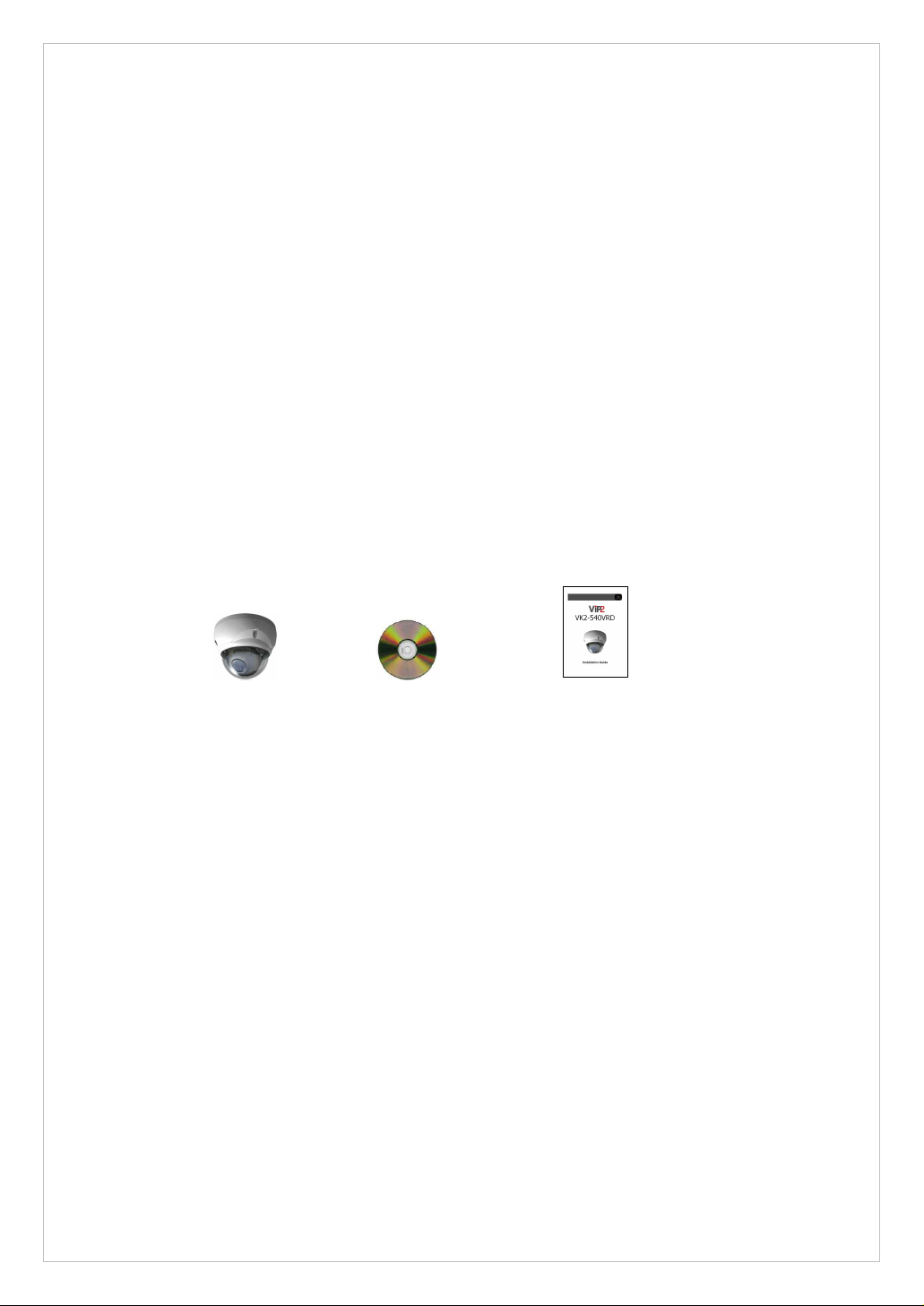
Components
The system comes with the following components:
VK2-540VRD Installation CD Installation Guide
Note: Check your package to make sure that you received the complete system, including
all components shown above.

8
Key Features
• Brilliant video quality
The VK2-540VRD offers the highly efficient H.264 video compression, which drastically
reduces bandwidth and storage requirements without compromising image quality. Motion
JPEG is also supported for increased flexibility.
• Dual streams
The VK2-540VRD can deliver dual video streams simultaneously at full frame rate in all
resolutions up to D1 (720x480 in NTSC, 720x576 in PAL) using Motion JPEG and H.264 (or
MPEG-4). This means that several video streams can be configured with different
compression formats, resolutions and frame rates for different needs.
• Image setting adjustment
The VK2-540VRD also enables users to adjust image settings such as contrast, brightness
and saturation to improve images before encoding takes place.
• Intelligent video capabilities
The VK2-540VRD includes intelligent capabilities such as enhanced video motion detection.
The encoder’s external inputs and outputs can be connected to devices such as sensors and
relays, enabling the system to react to alarms and activate lights or open/close doors.
• Power over Ethernet
Support for Power over Ethernet (IEEE802.3af) enables the unit, as well as the analog
camera that is connected to it, to receive power through the same cable as for data
transmission. This makes for easy installation since no power outlet is needed.
• Audio support
The VK2-540VRD also supports two-way audio.
• Improved Security
The VK2-540VRD logs all user access, and lists currently connected users. Also, its full
frame rate video can be provided over HTTPS.
• Camera
-. Superior image quality (540 TV Lines).
-. 0.3 Lux (Color) @ F1.2 Sensitivity.
-. C/CS, backfocus cam for easy adjustment.
-. Auto electronic shutter [1/60(1/50) ~ 1/100,000] and manual electronic shutter modes.
-. Full control via the OSD menu key on the side of the camera.
-. Auto and manual white balance modes.
-. BLC (Back Light Compensation)
-. Day&Night (Auto / Color / B/W)
-. AGC (Auto Gain Control)
-. Incredible noise reduction for picture quality & file size.
-. Sens-up (x2 ~ x128)
-. Privacy Zone 8 points.
-. MIRROR
-. VIDEO OUT(BNC)
9
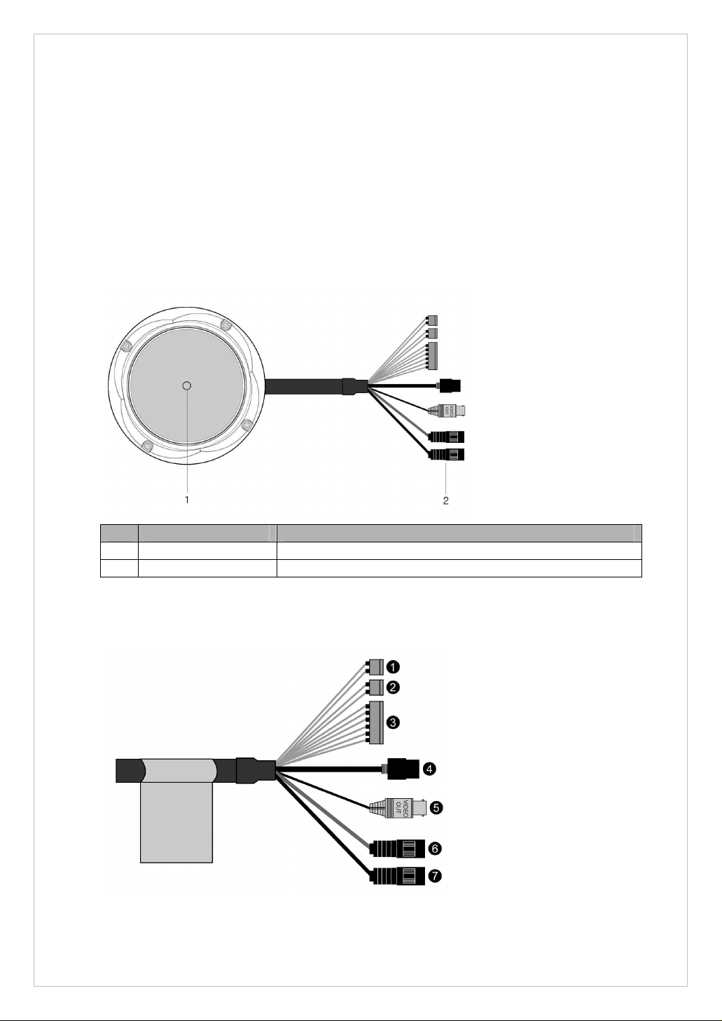
2. Installation
NO
Name
Description
1
Lens
Allows wide area to be monitored
2
Extension Cable
26pin camera extension cable
For the operation of the VK2-540VRD, it is necessary to connect a network cable for data
transmission, power connection from supplied power adapter and connect a general analog
camera. Depending on operation methods, it is possible to connect an alarm cable or audio
cable additionally. For its fixation on different locations, please consult with an installer.
Overview
• Top View
• Extension Cable
10
NO
Wire Color
Description
1
Red: AC24V/DC12V
White: AC24V/GND
Main Power, 2pin terminal, DC12V/AC24V, max. 6.5W
2
Orange: AC24V/DC12V
Black: AC24V/GND
Heater Power, 2pin terminal, max. 10Watt @ DC12V,
max. 20Watt @ AC24V
3
Pink: Alarm In
Yellowish Green: GND
Yellow: AD Key
Brown: GND
Light Blue: Alarm Out
Gray: GND
Alarm Input, AD Key Input, Alarm Output:
6pin terminal.
4
Black
Ethernet, RJ-45 port compatible with 10/100Mbps PoE.
Modular Jack
5
Black
Video Composite Output, BNC Jack
6
Gray
Audio line output, Stereo Jack
7
Black
Audio line input, Stereo Jack
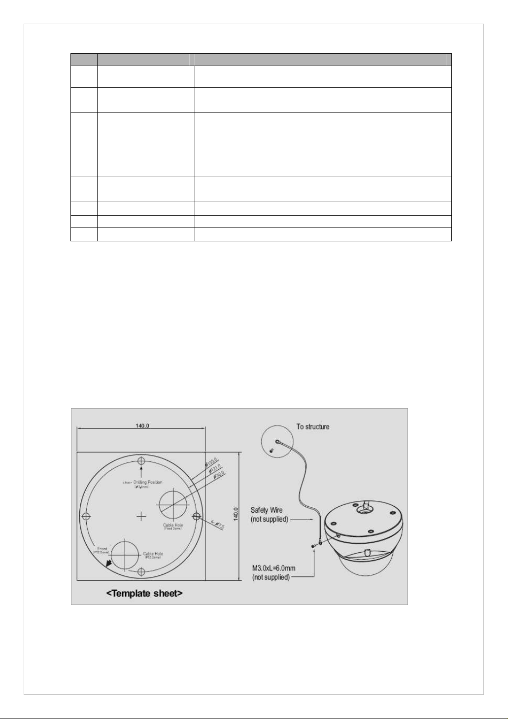
Caution: Never aim the camera directly into the sun.
Base Installation
1. Make mounting holes and cable hole in the place (ceiling) to which this dome camera
is installed using the supplied template sheet.
Warning: The total mass of the main unit is approx 1.3kg. Check whether the ceiling
to which the Dome Camera is installed is strong enough to hold the unit mass. If not,
the Dome Camera could fall, causing injury.
2. Attach the safety wire for securing the dome camera to ceiling or structure not to fall.
3. Extract each wire through the cable hole, connect BNC cable and communication lines.
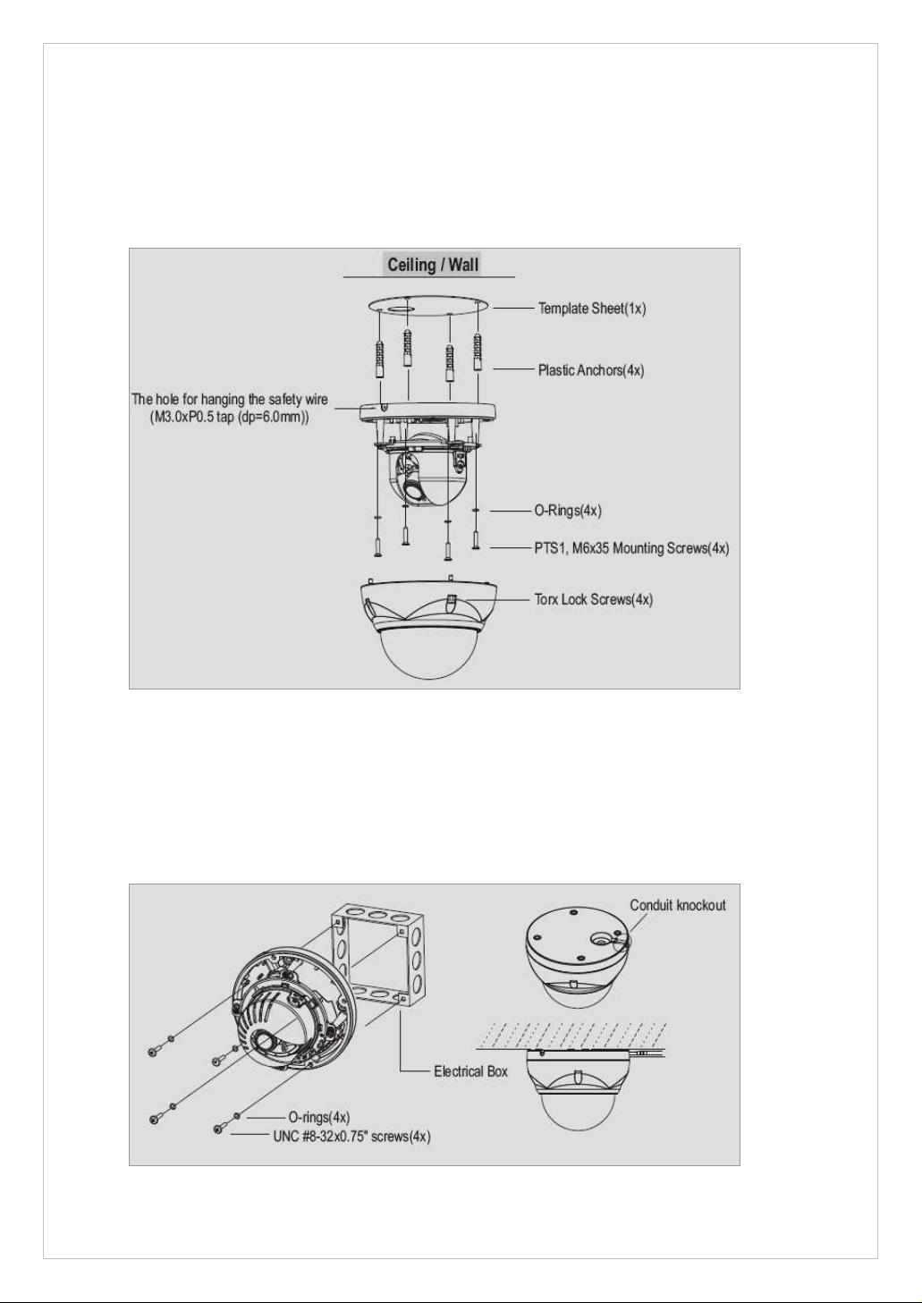
11
4. Unlock torx screws (4x) the dome cover and fix the dome case firmly with supplied
mounting screws (4x), plastic anchors (4x), O-Rings (4x).
5. Adjust desired focus and scene by turning and moving the hemisphere by hand.
6. Lock the housing cover with torx screws (4x).
• Cable through the electrical box with the dome base
The housing can also be mounted on a 4s or 2s electrical box.
• Using the conduit knockout punched with the dome base
Remove the conduit knockout punched for the cable entry.
12
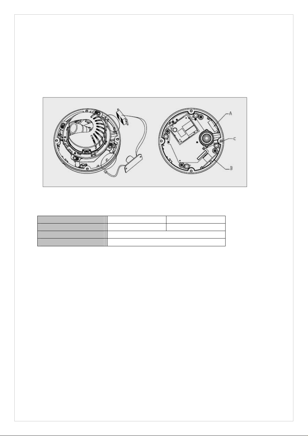
Heater Kit Installation
Power Supply
24VAC
12DCV
Power Consumption
20Watt
10Watt
Heater On
at 41°F (5°C)
Heater Off
at 59°F (15°C)
1. Place the heater element is slot “A”. Please ensure that the cables are facing upwards
and the heater is pointing towards the Dome.
2. Place the PCB in slot “B”. Please ensure that the PCB is facing inside of the Dome with
the connection blocks at the top.
3. Place the plug in the Socket “C” (J3) which is found on the controller board.
• Cheater (IF Applicable)
• Power
Use Certified/Listed Class 2 power source only.
13
Network Connection
The VK2-540VRD supports the operation through the network. Therefore, it is necessary to
connect a standard RJ-45 cable to it. Generally a cross-over cable is used for directly
connection to PC, while a direct cable is used for connection to a hub.
IP Assignment
When a camera, Encoder or Decoder is first connected to the network it has no IP address.
So, it is necessary to allocate an IP address to the device with the “Smart Manager” utility
on the CD.
1. Connect the VK2-540VRD to the network and power up.
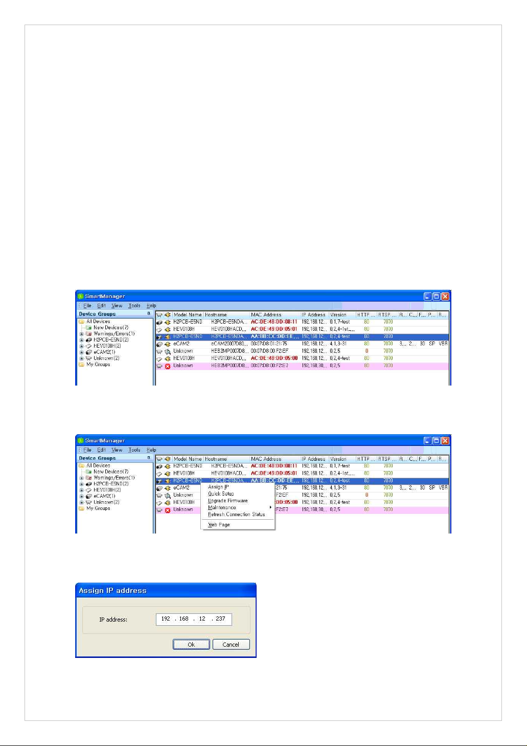
2. Start SmartManager utility (All programs > VIP2 > SmartManager), the main window
will be displayed, after a short while any cameras connected to the network will be
displayed in the list.
3. Select the camera on the list and click right button of the mouse. You can see the popup menu as below.
4. Select Assign IP. You cam see a Assign IP window.
Enter the required IP address.
14
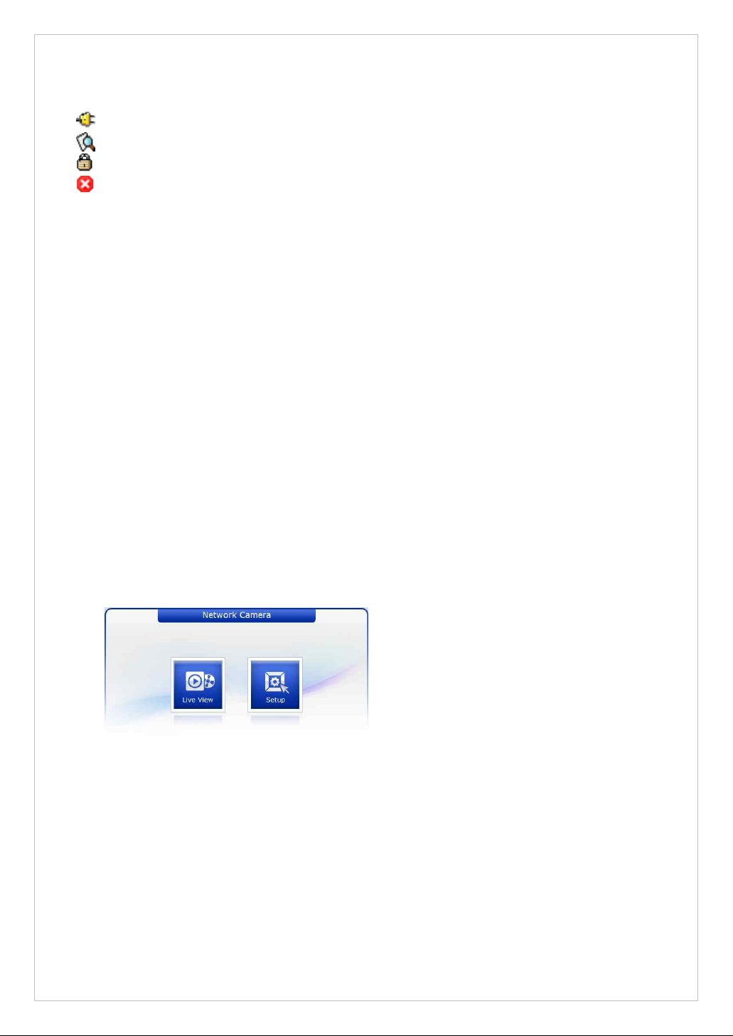
The description of each field for the connection status follows.
: Available for connection to the camera
: Loading settings information of video after connecting the camera.
: Connectable to the camera but fixed security settings (password)
: Unavailable for connection to the camera (PC can not access relevant IP Address)
Note: Refer to VIP2 Client Software User’s Manual for detailed information.
3. Operation
The VK2-540VRD can be used with most standard operating systems and browsers.
Notes: To view streaming video in Microsoft Internet Explorer, set your browser to allow ActiveX
controls.
3.1 Access from a browser
1. Start a browser (Internet Explorer).
2. Enter the IP address or host name of VK2-540VRD in the Location/Address field of
your browser.
3. You can see a starting page. Click Live View or Setup to enter web page.
15
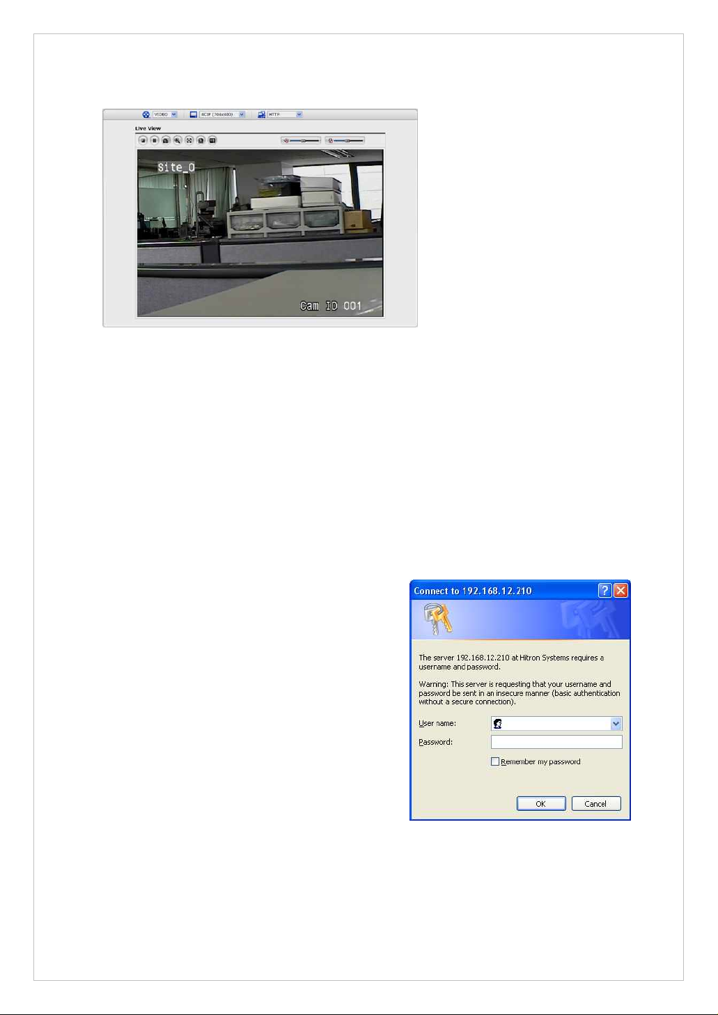
4. The encoder’s Live View page appears in your browser.
To gain access to the product, the password for
the default administrator user must be set. This
is done in the “Admin Password” dialog, which is
displayed when the VK2-540VRD is accessed for
the setup at the first time. Enter your admin
name and password, set by the administrator.
Note: The default administrator username and
password is “admin”. If the password is lost, the
VK2-540VRD must be reset to the factory default
settings. See “3.9 Resetting to the factory default
settings”.
3.2. Access from the internet
Access from the internet Once connected, the VK2-540VRD is accessible on your local
network (LAN). To access the VK2-540VRD from the Internet you must configure your
broadband router to allow incoming data traffic to it. To do this, enable the NAT-traversal
feature, which will attempt to automatically configure the router to allow access to the VK2-
540VRD. This is enabled from Setup > System > Network > NAT.
For more information, please see NAT traversal (port mapping) for IPv4, on page 61.
3.3 Setting the admin password over a secure connection
To prevent network eavesdropping when setting the admin password, this can be done via
an encrypted HTTPS connection, which requires an HTTPS certificate (see note below).
To set the password via a standard HTTP connection, enter it directly in the first dialog
shown below. To set the password via an encrypted HTTPS connection, see Setup >
System > Secutity > HTTPS, on page 52.
16
The live view page comes in eight
screen modes like 704x480(576),
704x240(288), 352x240(288),
176x120(144), 640x480, 320x240,
and 160x120. Users are allowed to
select the most suitable one out of
those modes. Please, adjust the
mode in accordance with your PC
specifications and monitoring
purposes.
Note:
HTTPS (Hypertext Transfer Protocol over SSL) is a protocol used to encrypt the traffic
between web browsers and servers. The HTTPS certificate controls the encrypted exchange
of information. The default administrator user cannot be deleted.
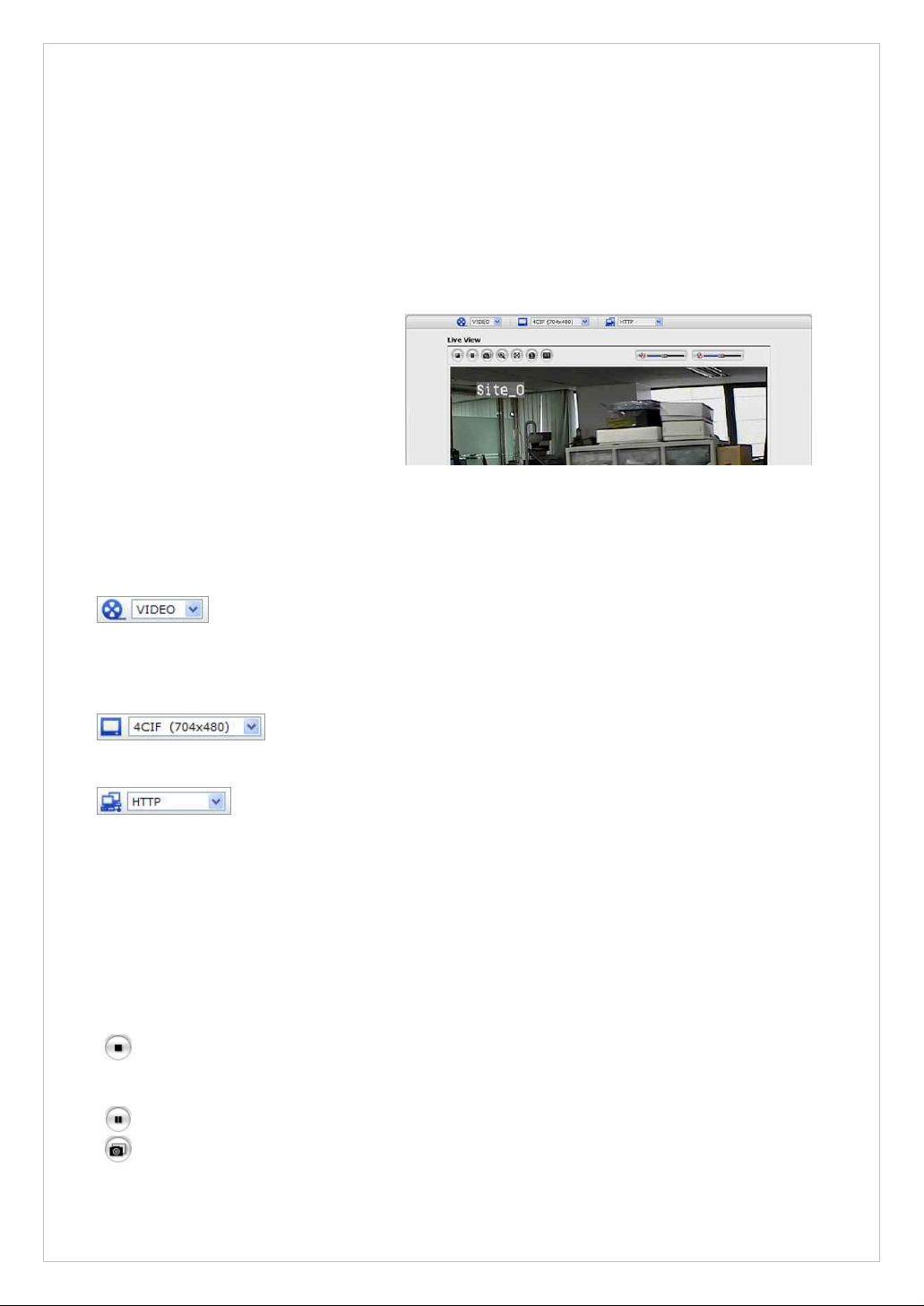
3.4 Live View Page
• General controls
The video drop-down list allows you to select a customized or preprogrammed video stream on the live view page. Stream profiles are configured under
Setup > Basic Configuration > Video & Image. See Basic Configuration, on page 25 for
more information.
The resolution drop-down list allows you to select the most suitable
one out of video resolutions to be displayed on live view page.
The protocol drop-down list allows you to select which combination of
protocols and methods to use depends on your viewing requirements, and on the
properties of your network.
• Control toolbar
The live viewer toolbar is available in the web browser page only. It displays the following
buttons:
The Stop button stops the video stream being played. Pressing the key again toggles the
start and stop. The Start button connects to the network camera or start playing a
video stream.
The Pause button pause the video stream being played.
The Snapshot button takes a snapshot of the current image. The location where the
image is saved can be specified.

17
The digital zoom activates a zoom-in or zoom-out function for video image on the live
screen.
The Full Screen button causes the video image to fill the entire screen area. No other
windows will be visible. Press the 'Esc' button on the computer keyboard to cancel full
screen view.
The Manual Trigger button activates a pop-up window to manually start or stop the
event.
The Camera Menu button activates a pop-up window for camera menu control.
Use this scale to control the volume of the speakers.
Use this scale to control the volume of the microphone.
Use this scale to control the volume of the speakers and microphones.
• Camera Menu controls
If the VK2-540VRD has been appropriately configured, the Live View page displays the
controls available for the OSD menu.
Please see “3.8 Camera Menu Control for more information.
• Video and Audio Streams
The camera can provide several images and video stream formats. Your requirements and
the properties of your network will determine the type you use.
The Live View page in the camera provides access to H.264, MPEG-4 and Motion JPEG
video streams, and to the list of available video streams. Other applications and clients can
also access these video streams/images directly, without going via the Live View page.
18
3.5 Camera Setup (Analog)
3.5.1 Settings
Settings can be made using the 5 buttons located on the back of the camera.
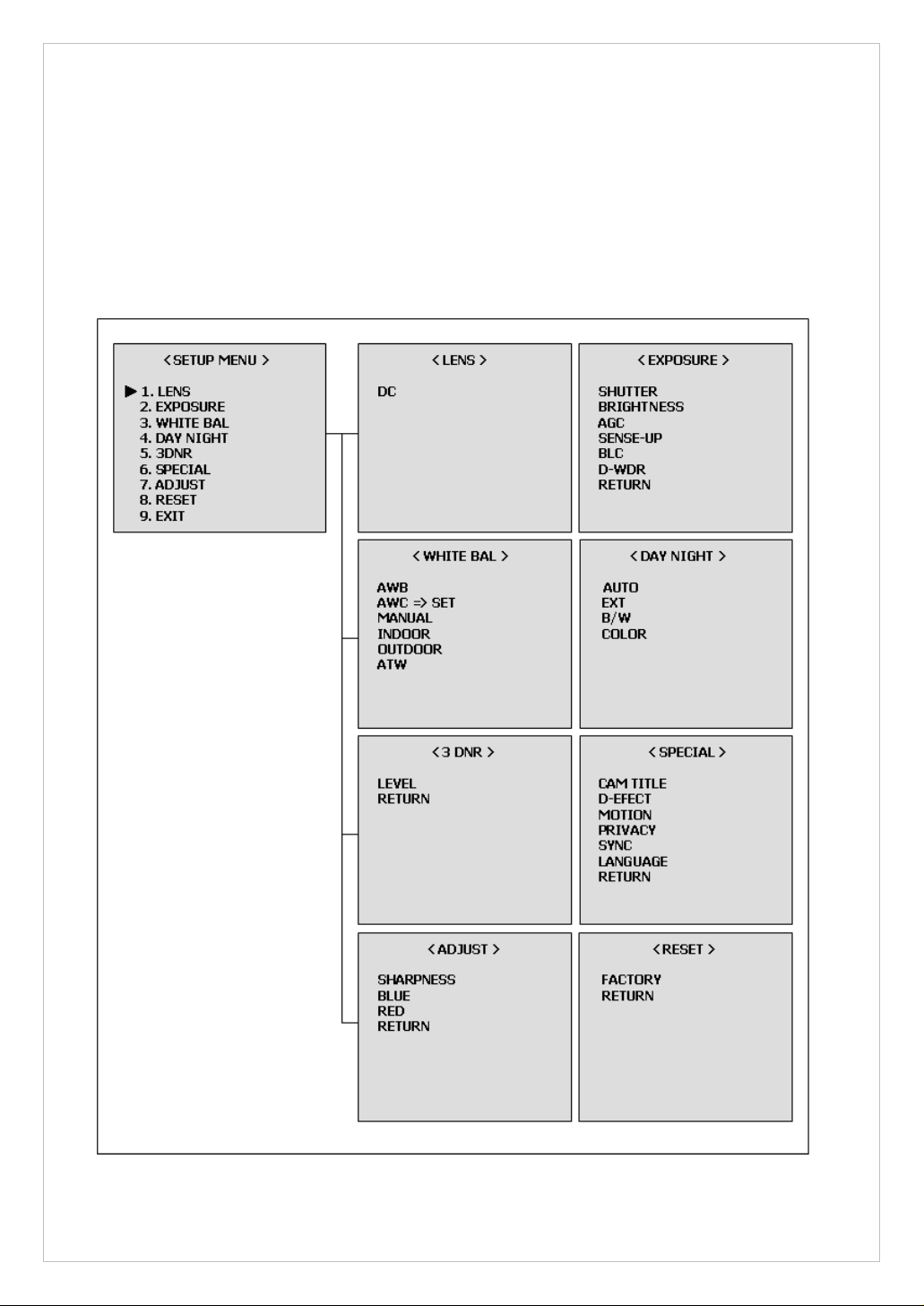
▶ Structure of menu setup
19
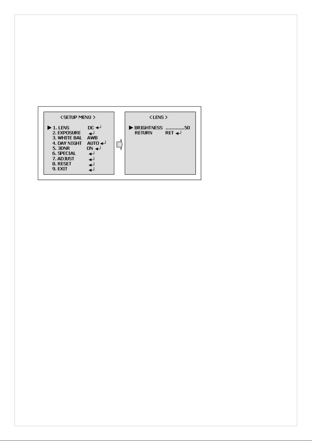
▶ LENS (Selection)
This function is used to adjust the brightness of the screen.
1. When the SETUP menu is displayed on the screen, please position the arrow to point
to LENS by using the UP and DOWN buttons.
2. Please select the type of the lens you wish to use by pressing the LEFT or RIGHT
button.
Note: The brightness of the screen can be adjusted in DC mode.
The brightness can be adjusted within the range of 0 ~ 100.
The optimum level of brightness for the user can be achieved by adjustment.
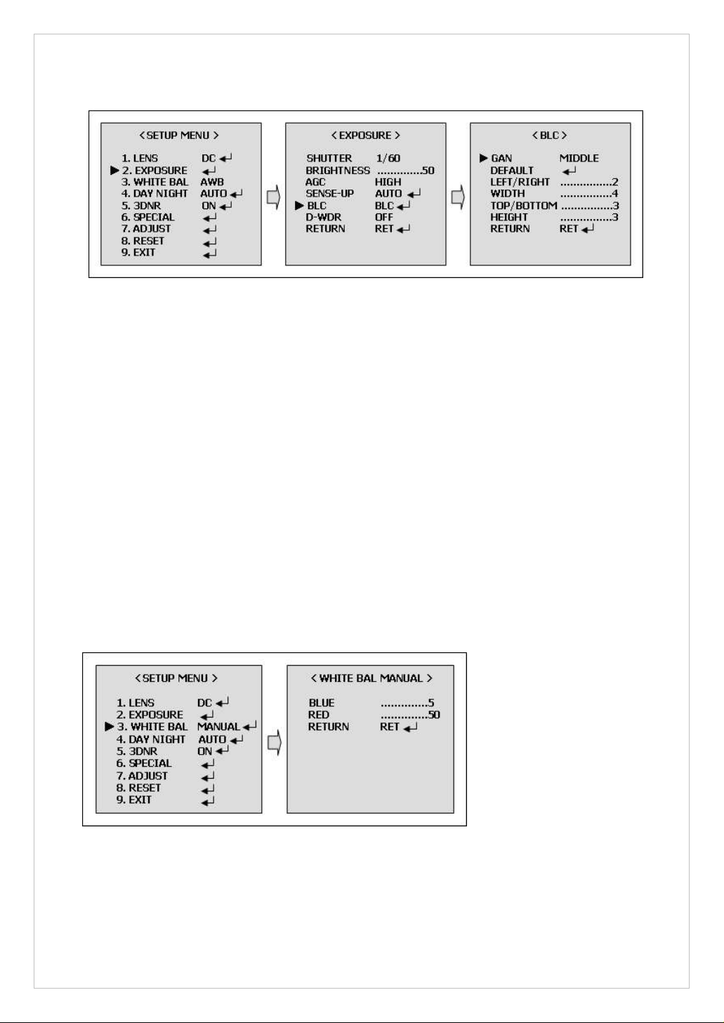
▶ EXPOSURE
The EXPOSURE menu is used to set the automatic light control method for this camera.
-. SHUTTER:
Select the shutter mode. (1/60(50), FLK~1/100,000 sec, x2~x256)
Can be changed while in shutter mode.
-. BRIGHTNESS:
Adjust BRIGHTNESS level (0~100).
Can be changed while in manual lens mode.
-. AGC:
Auto gain control (OFF/LOW/MIDDLE/HIGH)
-. SENSE-UP:
Use under very light condition for full color surveillance.
Select maximum Low-Shutter value. (x2 ~ x256)
-. BLC:
Sharpness subjects with backlight. (OFF/BLC/HBLC)
-. D-WDR:
Digital wide dynamic range. (OFF/INDOOR/OUTDOOR)
20
[BLC MODE]
▶ WHITE BAL
The Screen color can be adjusted by using the WHITE BALANCE function.
-. AWB:
Wide range auto white balance mode.
-. AWC => SET:
Please press the ENTER button while the camera is directed at a piece of while paper to
obtain the optimum state under current illumination. If the environment including the
light source is changed, you have to adjust the wide balance gain.
-. MANUAL:
Manual mode. User can change R and B gain manually.
-. INDOOR:
Set the color temperature to 3200K
-. OUTDOOR:
Set the color temperature to 6300K
-. ATW:
Set the color temperature to 2500K to 9500K
[WHITE BAL MANUAL MODE]
21
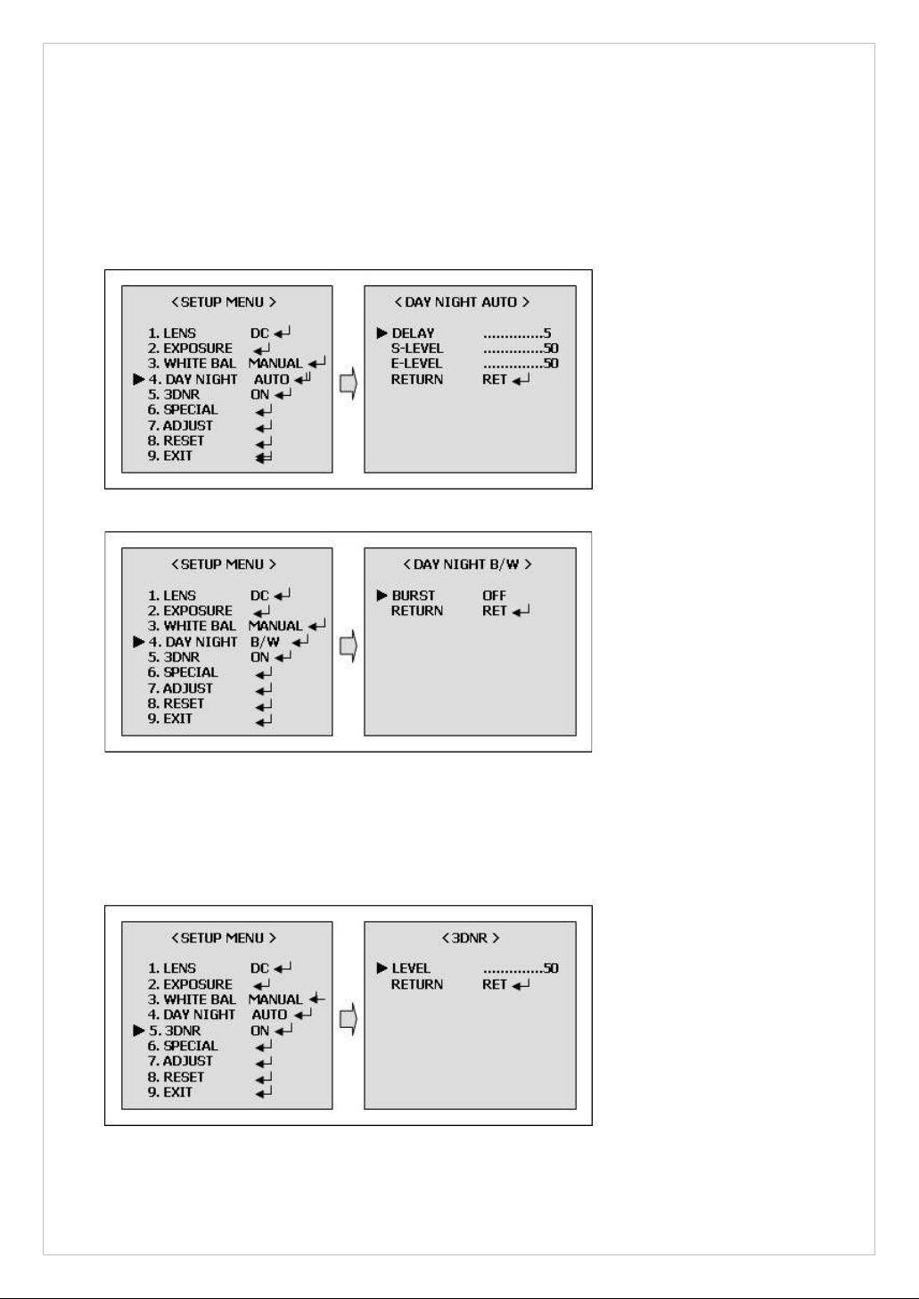
▶ DAY NIGHT
The DAT/NIGHT menu is used to configure the day and night related setting for this camera.
This camera can turn the IR(Infrared) filter on or off.
-. Mode: AUTO/EXT/BW/COLOR
[DAY/NIGHT AUTO MODE]
[DAY/NIGHT B/W MODE]
▶ 3DNR(Digital Noise Reduction)
You can configure the DNR(Digital Noise Reduction) related settings. If you press the Setup
switch when ON is selected in 3DNR, the corresponding screen appears.
22
▶ SPECIAL
1. CAM TITLE
-. A CAM TITLE : Camera Title
-. B 0123456789ABCD : Character Table
EFGHIJKLMNOPQRSTUVWXYZ
▶→←↑↓()−_▐ /=&:~,”
-. C ←→CLR POS END : ←, Move to left
:→, Move to right
: CLR, Erase all characters
: POS, Move the position of title
: END, Save and End
2. D-EFFECT
-. FREEZE: Select the real or still mode.
-. MIRROR: Reverse the screen in 3 modes selection. (OFF/MIRROR/V FLIP/ROTATION)
-. D-ZOOM: D-Zoom (x2~x32) / Adjust PAN/TILT
-. GAMMA: Adjust the luminance. (0.05~1.00)
-. NEGA/POSI: Select the negative or positive mode.
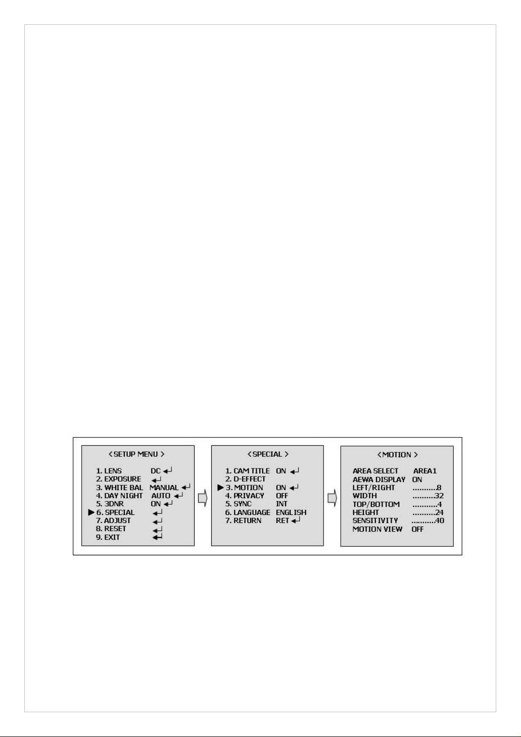
3. MOTION
-. AREA SELECT: Select MD area number.
-. AREA DISPLAY: Select MD ON/OFF.
-. LEFT/RIGHT: Adjust the location of the MD area with boundary LEFT and RIGHT.
-. WIDTH: Adjust width of MD area.
-. TOP/BOTTOM: Adjust the location of the MD area with boundary TOP and BOTTOM
-. HEIGHT: Adjust the height of MD area.
-. SENSITIVITY: Adjust sensitivity of MD area. (0~40)
-. MOTION VIEW: The screen displays with green dots. When a motion is detected in
the selected area, the green dots are displayed on the screen.
23
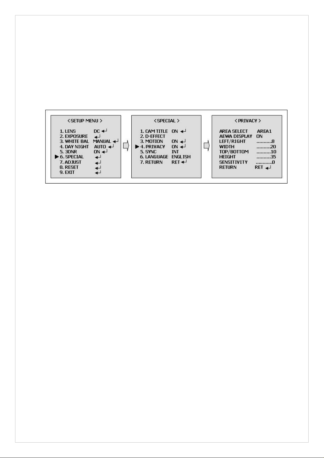
4. PRIVACY
-. AREA SELECT: Select MAK area number.
-. AREA DISPLAY: Select MASK ON/OFF.
-. LEFT/RIGHT: Adjust the location of the MASK area with boundary LEFT and RIGHT.
-. WIDTH: Adjust width of MASK area.
-. TOP/BOTTOM: Adjust the location of the MASK area with boundary TOP and BOTTOM.
-. HEIGHT: Adjust the height of MASK area.
-. COLOR: Select MASK color. (0~15)
[PRIVACY MODE]
5. SYNC: Select Internal or Line Lock mode.
-. INT: This mode is necessary for using the internal synchronization.
-. L/L: This mode is necessary for the operation of multi camera because it synchronizes
the camera phase by using the external signal (AC Signal).
-. PAHSE: Sync phase is adjustable in line lock mode.
6. LANGUAGE : You can change the OSD language using the LEF/RIGHT Setup switch.
▶ ADJUST
1. SHARPNESS: Can be adjusted SHARPNESS of outlines. (0~31)
2. BLUE: Adjust B-GAIN value. (0~100)
3. RED: Adjust R-GAIN value. (0~100)
▶ PRESET
1. FACTORY: Returns to the level which was set by the manufacturer.
▶ EXIT
1. EXIT: Saves all the setting menus and then exits.
 Loading...