

Vista VK2-3MPBIR3V9F User Manual
Please read this manual thoroughly before use, and keep it handy for future reference.
VK2-3MPBIR3V9F
User manual

2

3

4
Before You Begin
Read these instructions before installing or operating this product.
Note: This installation should be made by a qualified service person and should conform to local codes.
This manual provides installation and operation information. To use this document, you must have the following
minimum qualifications:
A basic knowledge of CCTV systems and components
A basic knowledge of electrical wiring and low-voltage electrical connections
Intended use
Only use this product for its designated purpose; refer to the product specification and user documentation.
Customer Support
For assistance in installing, operating, maintaining and troubleshooting this product refer to this document and
any other documentation provided. If you still have questions, please contact Norbain Technical Support and
Sales:
Norbain SD Ltd, 210 Wharfedale Road, IQ Winnersh, Wokingham, Berkshire RG41 5TP,
England.
UK +44 (0) 118 912 5000
Note: You should be at the equipment and ready with details before calling Technical Support.
Conventions Used in this Manual
Boldface or button icons highlight command entries. The following WARNING, CAUTION and Note statements
identify potential hazards that can occur if the equipment is not handled properly:
* WARNING:
Improper use of this equipment can cause severe bodily injury or equipment damage.
** Caution:
Improper use of this equipment can cause equipment damage.
Note: Notes contain important information about a product or procedure.
This apparatus is manufactured to comply with the radio interference.
A Declaration of Conformity in accordance with the following EU standards has been made. The
manufacturer declares that the product supplied with this document is compliant the provisions of
the EMC Directive 2004/108/EC, the CE Marking Directive 93/68 EEC and all associated
amendments.
All lead-free products offered by the company comply with the requirements of the European law
on the Restriction of Hazardous Substances (RoHS) directive: 2011/65/EU, which means our
manufacture processes and products are strictly “lead-free” and without the hazardous

5
substances cited in the directive.
The crossed-out wheeled bin mark symbolizes that within the European Union the product must be
collected separately at the product end-of-life. This applies to your product and any peripherals
marked with this symbol. Do not dispose of these products as unsorted municipal waste.
* This symbol indicates electrical warnings and cautions.
** This symbol indicates general warnings and cautions.
NORBAIN SD LTD reserves the right to make changes to the product and specification of the product from time to
time without prior notice.
To reduce the risk of fire or electric shock, do not insert any metallic objects through the ventilation grills or other
openings on the equipment.

6
IMPORTANT SAFETY INSTRUCTIONS
Read these instructions.
1. Keep these instructions.
2. Heed all warnings.
3. Follow all instructions.
4. Do not use this apparatus near water.
5. Clean only with dry cloth.
6. Do not block any ventilation openings. Install in accordance with the manufacturer’s instructions.
7. Do not install near any heat sources such as radiators, heat registers, stoves, or other
apparatus (including amplifiers) that produce heat.
8. Do not defeat the safety purpose of the polarized or grounding-type plug. A polarized plug has
two blades with one wider than the other. A grounding type plug has two blades and a third
grounding prong. The wide blade or the third prong is provided for your safety. If the provided
plug does not fit into your outlet, consult an electrician for replacement of the obsolete outlet.
9. Protect the power cord from being walked on or pinched particularly at plugs, convenience
receptacles, and the point where they exit from the apparatus.
10. Only use attachments/accessories specified by the manufacturer.
11. Use only with the cart, stand, tripod, bracket, or table specified by the
manufacturer, or sold with the apparatus. When a cart is used, use caution
when moving the cart/apparatus combination to avoid injury from tip-over.
12. Unplug this apparatus during lightning storms or when unused for long periods
of time.
13. Refer all servicing to qualified service personnel. Servicing is required when the apparatus has
been damaged in any way, such as power-supply cord or plug is damaged, liquid has been
spilled or objects have fallen into the apparatus, the apparatus has been exposed to rain or
moisture, does not operate normally, or has been dropped.
14. CAUTION – THESE SERVICING INSTRUCTIONS ARE FOR USE BY QUALIFIED SERVICE
PERSONNEL ONLY. TO REDUCE THE RISK OF ELECTRIC SHOCK DO NOT PERFORM
ANY SERVICING OTHER THAN THAT CONTAINED IN THE OPERATING INSTRUCTIONS
UNLESS YOU ARE QUALIFIED TO DO SO.
15. Use satisfy clause 2.5 of IEC60950-1/UL60950-1 or Certified/Listed Class 2 power source only.
16. ITE is to be connected only to PoE networks without routing to the outside plant.
CE COMPLIANCE STATEMENT
WARNING
This is a Class A product. In a domestic environment this product may cause radio
interference in which case the user may be required to take adequate measures.

7
Contents
Before You Begin ............................................................................................... 4
Intended use ....................................................................................................... 4
Customer Support .............................................................................................. 4
1. Description ..................................................................................................... 8
1.1 Components ............................................................................................................. 8
1.2 Key Features ............................................................................................................ 9
1.3 Overview ................................................................................................................. 10
2. Installation .................................................................................................... 13
2.1 Connection ............................................................................................................. 13
2.2 Network Connection and IP assignment ............................................................ 15
3. Operation ...................................................................................................... 16
3.1 Access from a browser ......................................................................................... 16
3.2. Access from the internet ..................................................................................... 17
3.3 Setting the admin password over a secure connection ................................... 17
3.4 Live View Page ........................................................................................... 17
3.5 Network Camera Setup ......................................................................................... 20
3.5.1 Basic Configuration .............................................................................................................. 20
3.5.2 Live View ............................................................................................................................... 20
3.5.3 Video & Image ...................................................................................................................... 27
3.5.4 Event ..................................................................................................................................... 32
3.5.5 System .................................................................................................................................. 45
3.5.6 About ..................................................................................................................................... 66
3.6 Playback ................................................................................................................. 67
3.7 Help ......................................................................................................................... 69
3.8 Resetting to the factory default settings ................................................................................ 70
4. Appendix ....................................................................................................... 71
4.1 Troubleshooting .................................................................................................... 71
4.2 Preventive Maintenance ....................................................................................... 72
4.3 Product Specification ........................................................................................... 73
8
1. Description
The Network Camera supports the network service for a sensor image with progressive scan, which
can be monitored on a real-time screen regardless of distances and locations. By using its dedicated
program, many users are able to have an access to the Network Camera at once or a single user can
monitor various network cameras at the same time. It also enables users to play, store and retrieve a
monitoring image by using a PC. All the settings and real-time monitoring screens are also provided
through an access to the web.
The Network Camera is fully featured for security surveillance and remote monitoring needs. It is
based on the DSP compression chip, and makes it available on the network as real-time, full frame
rate Motion JPEG and H.264 (or MPEG-4) video streams.
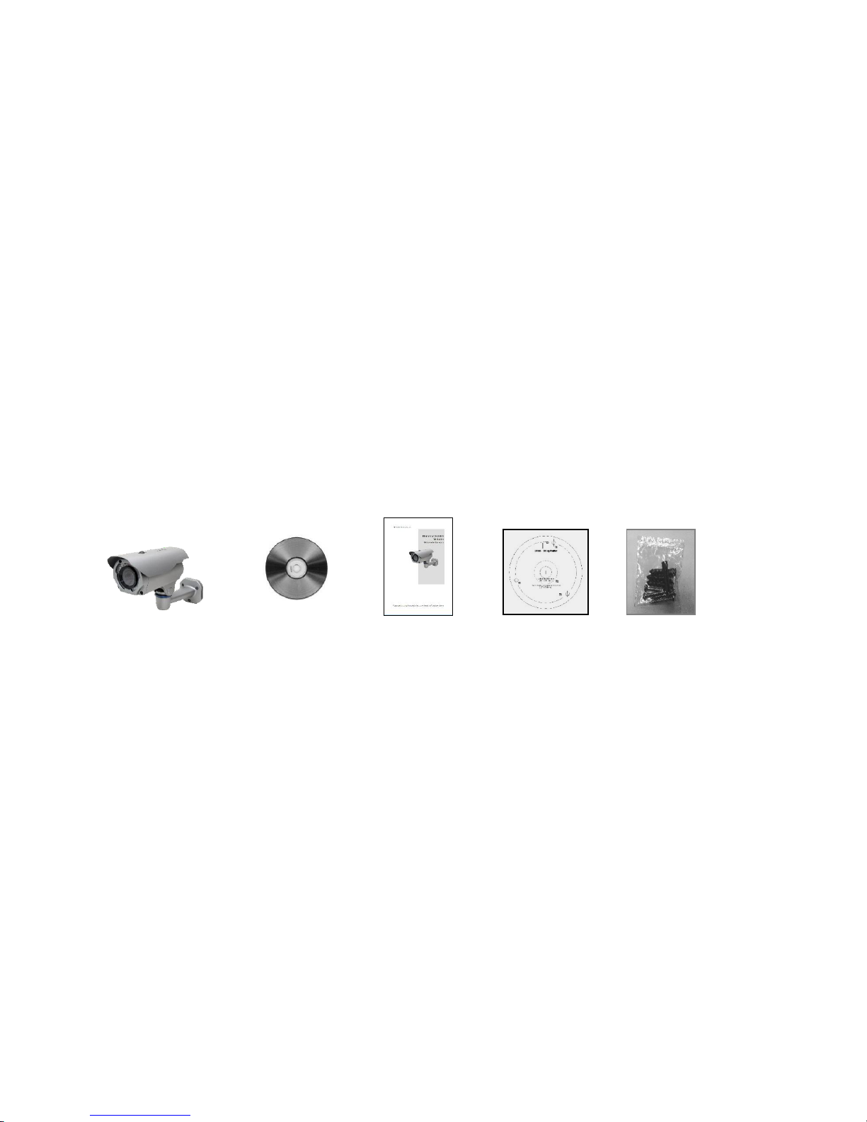
1.1 Components
The system comes with the following components:
Camera unit Installation CD Installation Guide Template Sheet Accessory Kit
NOTE: Check your package to make sure that you received the complete system, including all
components shown above.

9
1.2 Key Features
• Brilliant video quality
The Network Camera offers the highly efficient H.264 video compression, which drastically
reduces bandwidth and storage requirements without compromising image quality. Motion JPEG
is also supported for increased flexibility.
• Wide Dynamic Range
The network camera provides WDR (Wide Dynamic Range) that improves video exposure quality
in scenes with high contrast between bright and dark areas in the video, for example a shady
area and a sunny area in the same scene.
• Dual or triple streams
The Network Camera can deliver dual or triple video streams simultaneously at full frame rate in
all resolutions up to 3M (2048 x 1536p) using Motion JPEG and H.264 (or MPEG-4). This means
that several video streams can be configured with different compression formats, resolutions and
frame rates for different needs.
• Image setting adjustment
The Network Camera also enables users to adjust image settings such as contrast, brightness
and saturation to improve images before encoding takes place.
• Intelligent video capabilities
The Network Camera includes intelligent capabilities such as enhanced video motion detection.
• Easy Focus
Easy Focus will be activated once Day/Night mode switched, and the focus readjusted
automatically.
• Focus & Zoom Control via Network
The Network Camera also enables users to adjust focus and zoom remotely via network.
• Resolution
3 Megapixel, Max. 20fps@2048x1536, 30fps@1920x1080
• Micro-SD Recording support
The Network Camera also supports a micro-SD memory slot for local recording with removable
storage.
• Improved Security
The Network Camera logs all user access, and lists currently connected users. Also, its full frame
rate video can be provided over HTTPS.
• ONVIF
This is a global interface standard that makes it easier for end users, integrators, consultants,
and manufacturers to take advantage of the possibilities offered by network video technology.
ONVIF enables interoperability between different vendor products, increased flexibility, reduced
cost, and future-proof systems.
10
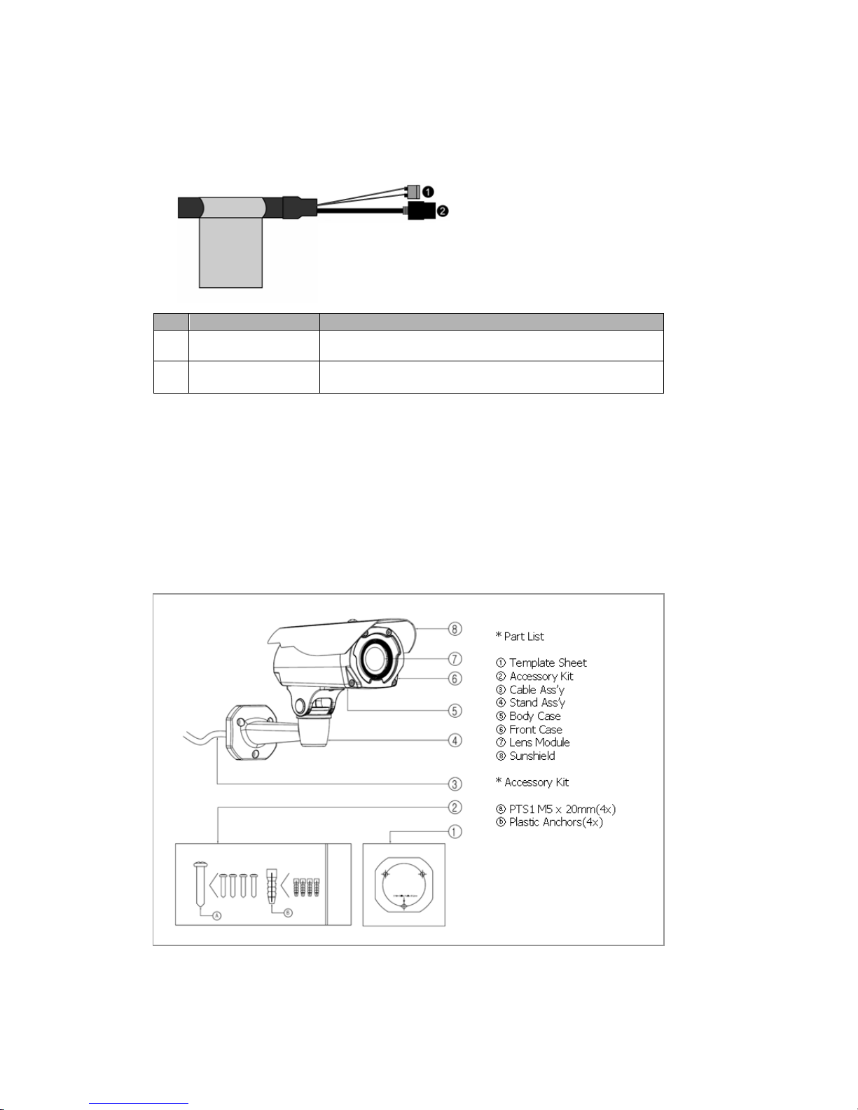
1.3 Overview
• Connection Cable
NO
Wire Color
Description
1
Red: DC12V
White: GND
Main Power, 2pin terminal, DC12V 2.5A(24W) with Heater,
or DC12V 550mA(6.5W) without Heater )
2
Black
Ethernet, RJ-45 port compatible with 10/100Mbps having PoE
functionality. Modular Jack
Caution: If using PoE, the heater will not operate at all.
Parts and Description
Carefully remove the contents from the box, and verity that nothing was damaged in shipment.
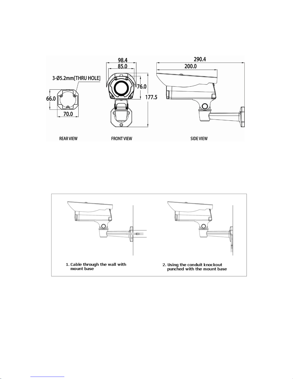
11
Camera Dimension
See the diagrams below for the exact dimension of the NUT-4201D, IR Bullet network cameras.
Dimensions Unit: mm
Base Installation(Cable through the wall with the mount base)
There are two ways of installing the camera.
12
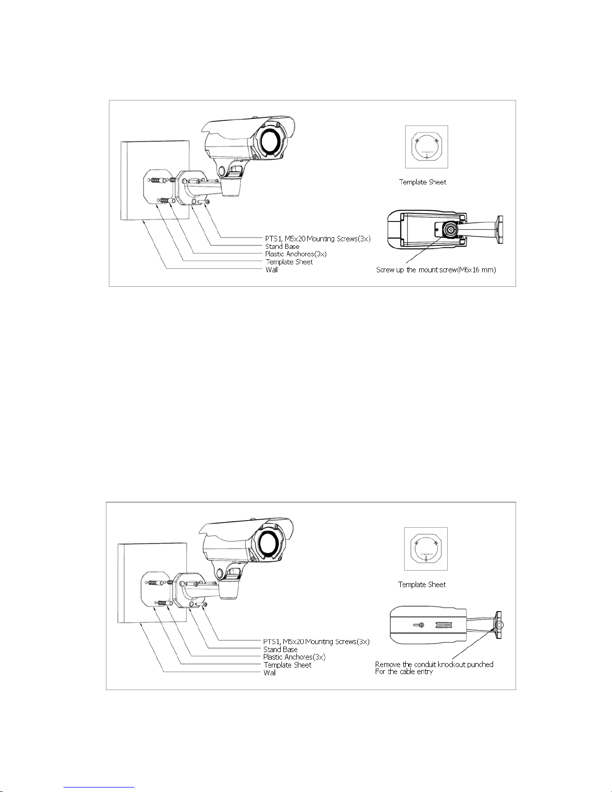
1) Installation1 (Cable through the wall with the mount base)
A. Drill the mounting location, using the template sheet (or the bottom of the mount base) as a
template.
B. Insert the plastic anchors into the hole which has just drilled.
C. Connect connection cable and network lines.
D. Fit the screw holes of the mount base into the plastic anchors.
E. Screw up the mount screws (M5x20).
F. Adjust the camera suitably, and fasten the mount screws (M6x16) to fix the camera.
2) Installation 2 (Using the conduit knockout punched with Mount Base)
A. Drill the mounting location, using the template sheet (or the bottom of the mount base) as a
template.
B. Insert the plastic anchors into the hole which has just drilled.
13
C. Connect connection cable and network lines.
D. Fit the screw holes of the mount base into the plastic anchors.
E. Remove the conduit knockout punched for the cable entry.
F. Screw up the mount screws (M5x20).
G. Adjust the camera suitably using the pan & tilt function, and fasten and fasten the mount
screws (M6x16) to fix the camera.
2. Installation
2.1 Connection
• Connecting to the RJ-45
Connect a standard RJ-45 cable to the network port of the network camera. Generally a
cross-over cable is used for directly connection to PC, while a direct cable is used for connection
to a hub.
You can also use a router featuring PoE (Power over Ethernet) to supply power to the camera.
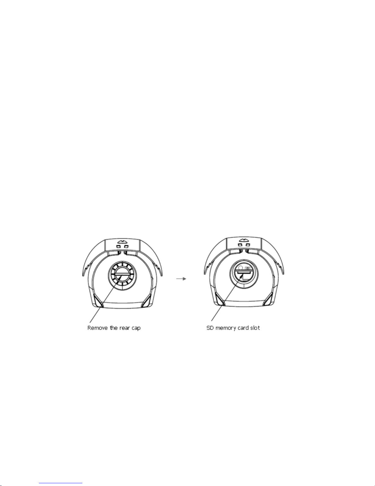
Micro SD memory slot on the Rear Board
Remove the rear cap of the camera to insert the SD memory card.
• Connecting the Power
Connect the power of DC12V for the network camera. Connect the positive(+) pole to the ‘+’
position and the negative(-) pole to the ‘-‘ position for the DC power.
Be careful not to reverse the polarity when you connect the power cable.
You can also use a router featuring PoE (Power over Ethernet) to supply power to the
camera.
The heater will operate properly only by the power source of DC 12V.
If using PoE, the heater will not operate at all.
If PoE and DC 12V are both applied, this camera will get supplied with power from PoE.
14
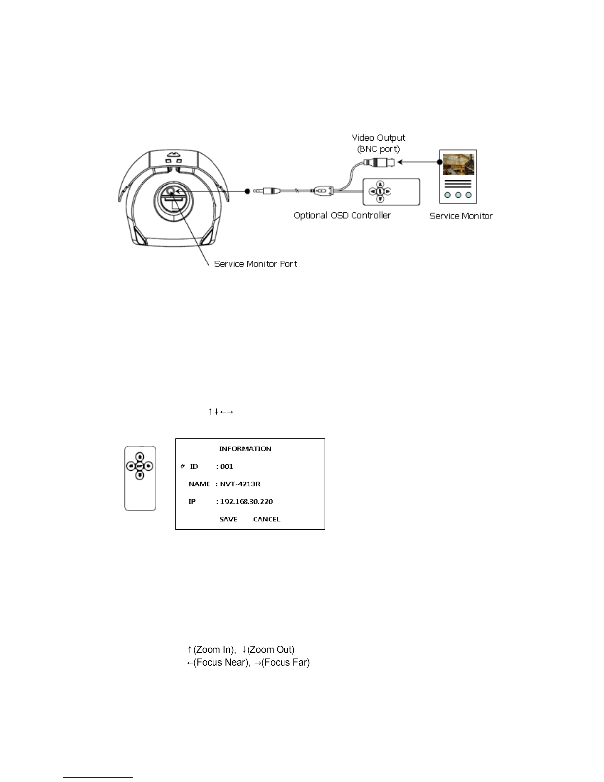
• Connecting Service Monitor Port
Service monitor port is used for an easy OSD setup. To make changes in the OSD menu, please
use the OSD controller provided optionally with your camera purchase. You can set Camera Title
and IP Address.
▶ ID & IP assignment
To make changes in the OSD menu, please use the OSD controller provided optionally with your
camera purchase. You can set Camera Title and IP Address.
1. Connect the OSD Controller to the Service Monitor port of the network camera.
2. Connect Service Monitor and the Video Output port of the OSD Controller.
3. Press the SET button to access main Menu.
4. Change Camera ID, and IP Address. You can change the Name or Title and IP address of the
camera. Using the buttons on the controller, you can change the parameters.
5. Select SAVE or CANCEL to exit the Main Menu.
Video Output is also used for an easy zoom and focus control when installing lens. Video Output
is restricted to 704x480(576) resolution.
▶ Zoom & Focus Control
The camera enters Zoom and Focus control mode as soon as connecting OSD Controller to the
Service Monitor port.
-. Zoom Control:
-. Focus Control:
-. Smart Focus: Press and hold the SET button for 2 or more seconds. The camera readjusts
focus automatically.
Note: You can get the Optional OSD Controller from your installer.
15
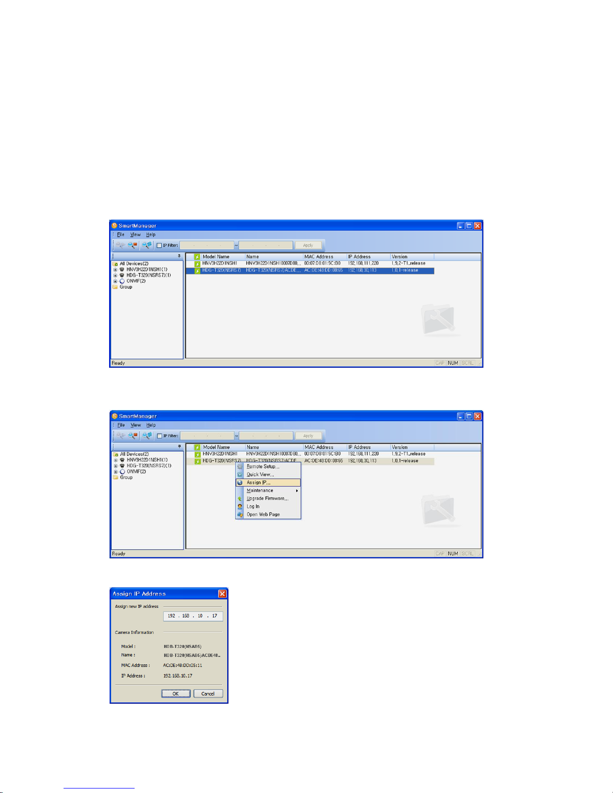
2.2 Network Connection and IP assignment
The Network Camera supports the operation through the network. When a camera is first connected
to the network it has no IP address. So, it is necessary to allocate an IP address to the device with the
“Smart Manager” utility on the CD. The factory default IP is “192.168.30.220”.
1. Connect the Network Camera / device to the network and power up.
2. Start SmartManager utility (Start>All programs>SmartManager>SmartManager), the main
window will be displayed, after a short while any network devices connected to the network will
be displayed in the list.
3. Select the camera on the list and click right button of the mouse. You can see the pop-up menu
below.
4. Select Assign IP. You cam see a Assign IP window. Enter the required IP address.
Note: For more information, refer to the Smart Manger User’s
Manual.
16
3. Operation
The Network Camera can be used with Windows operating system and browsers. The recommended
browsers are Internet Explorer, Safari, Firefox, Opera and Google Chrome with Windows.
Note: To view streaming video in Microsoft Internet Explorer, set your browser to allow ActiveX
controls.
3.1 Access from a browser
1. Start a browser (Internet Explorer).
2. Enter the IP address or host name of the Network Camera in the Location/Address field of your
browser.
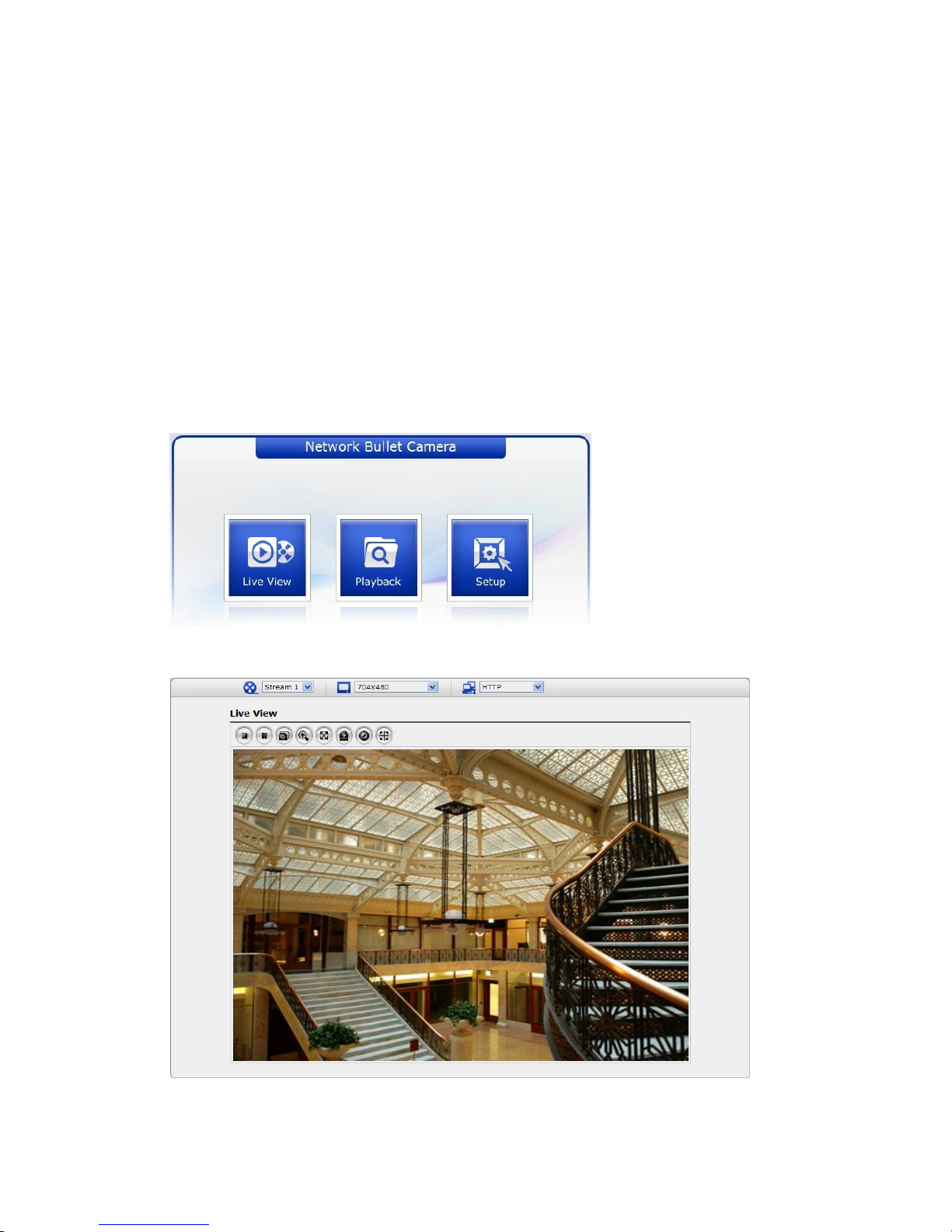
3. You can see a starting page. Click Live View or Setup to enter web page.
4. The network camera’s Live View page appears in your browser.
17
3.2. Access from the internet
Access from the internet once connected, the Network Camera is accessible on your local network
(LAN). To access the network camera from the Internet you must configure your broadband router to
allow incoming data traffic to the network camera. To do this, enable the NAT-traversal feature, which
will attempt to automatically configure the router to allow access to the network camera. This is
enabled from Setup > System > Network > NAT.
For more information, please see “3.5.6 System>Network>NAT” of User’s Manual.
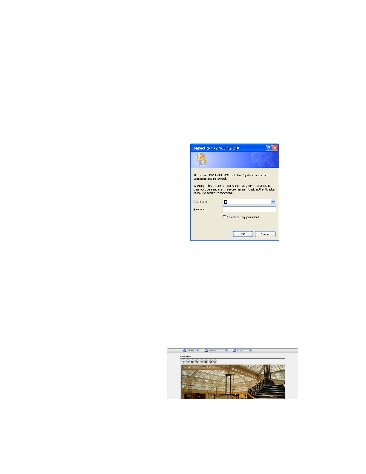
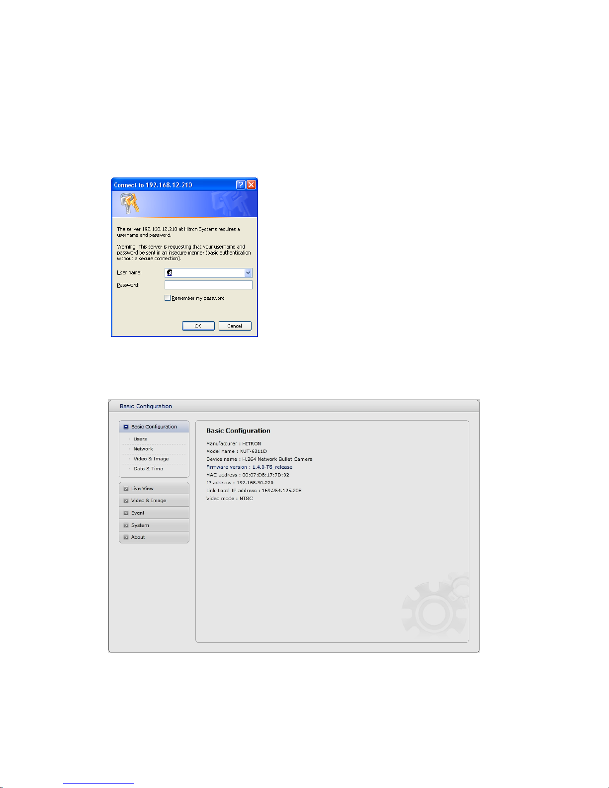
3.3 Setting the admin password over a secure connection
To gain access to the product, the password for
the default administrator user must be set. This
is done in the “Admin Password” dialog, which is
displayed when the network camera is accessed
for the setup at the first time. Enter your admin
name and password, set by the administrator.
Note: The default administrator username and
password is “admin”. If the password is lost, the
Network Camera must be reset to the factory
default settings. See “3.8 Resetting to the Factory
Default Settings”.
To prevent network eavesdropping when setting the admin password, this can be done via an
encrypted HTTPS connection, which requires an HTTPS certificate (see note below).
To set the password via a standard HTTP connection, enter it directly in the first dialog shown below.
To set the password via an encrypted HTTPS connection, see “3.5.6 System >Security>HTTPS”.
Note: HTTPS (Hypertext Transfer Protocol over SSL) is a protocol used to encrypt the traffic between
web browsers and servers. The HTTPS certificate controls the encrypted exchange of information.
3.4 Live View Page
The live view page comes in several
screen modes: 2048x1536, 1920x1080,
1280x1024, 1280x720, 704x480(576),
640x480, 352x240(288) and 320x240.
Users are allowed to select the most
suitable one out of those modes. Please,
adjust the mode in accordance with your
PC specifications and monitoring
purposes.
18
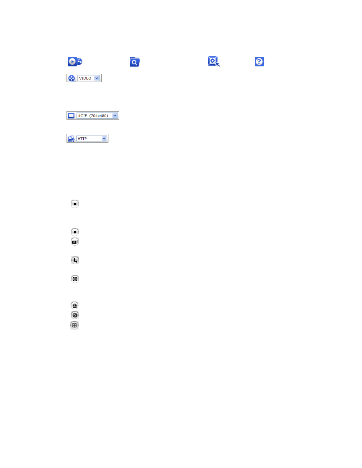
1) General controls
Live View Page Search & Playback Page Setup Page Help Page
The video drop-down list allows you to select a customized or pre-programmed
video stream on the live view page. Stream profiles are configured under Setup > Basic
Configuration > Video & Image. For more information, please see “3.5.1 Basic Configuration >
Video & Image” of User’s Manual.
The resolution drop-down list allows you to select the most suitable one
out of video resolutions to be displayed on live view page.
The protocol drop-down list allows you to select which combination of
protocols and methods to use depends on your viewing requirements, and on the properties of
your network.
2) Control toolbar
The live viewer toolbar is available in the web browser page only. It displays the following
buttons:
The Stop button stops the video stream being played. Pressing the key again toggles the
start and stop. The Start button connects to the network camera or start playing a
video stream.
The Pause button pause the video stream being played.
The Snapshot button takes a snapshot of the current image. The location where the
image is saved can be specified.
The digital zoom activates a zoom-in or zoom-out function for video image on the live
screen.
The Full Screen button causes the video image to fill the entire screen area. No other
windows will be visible. Press the 'Esc' button on the computer keyboard to cancel full
screen view.
The Manual Trigger button activates a pop-up window to manually start or stop the event.
The Remote Focus button enables users to adjust focus and zoom remotely via network.
The Smart Focus button readjusts focus automatically.
3) Video Streams
The network camera provides several images and video stream formats. Your requirements and
the properties of your network will determine the type you use.
The Live View page in network camera provides access to H.264, MPEG-4 and Motion JPEG video
streams, and to the list of available video streams. Other applications and clients can also access
these video streams/images directly, without going via the Live View page.
19
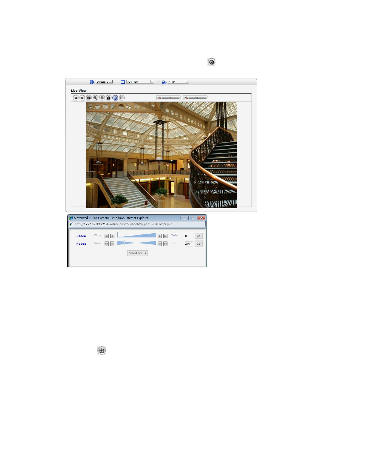
4) Focus and Zoom Control
You can control Zoom and Focus in the live screen. Press the button on the left top in the live
screen to activate the Zoom & Focus control panel.
• Adjusting Zoom:
Click “<” button to zoom out and click “>” button to zoom in. The focus is moved slightly after
adjusting zoom; adjust the focus again, as necessary.
• Adjusting Focus:
Click “>” button for far focus and click “<” button to near focus.
• Fine Focus:
Click “Fine Focus” to fine tune and readjust focus automatically.
Note: Click the button in the Live View screen to set the focus to the optimum position.
20
3.5 Network Camera Setup
This section describes how to configure the network camera, and is intended for product
Administrators, who have unrestricted access to all the Setup tools; and Operators, who have access
to the settings for Basic, Live View, Video & Image, Event, and System Configuration.
You can configure the network camera by clicking Setup in the top right-hand corner of the Live View
page. Click on this page to access the online help that explains the setup tools
When accessing the Network Camera for the first time,
the “Admin Password” dialog appears. Enter your
admin name and password, set by the administrator.
Note: If the password is lost, the Network Camera
must be reset to the factory default settings. See “3.8
Resetting to the Factory Default Settings”.
3.5.1 Basic Configuration
You can see the device information in this information page.
21
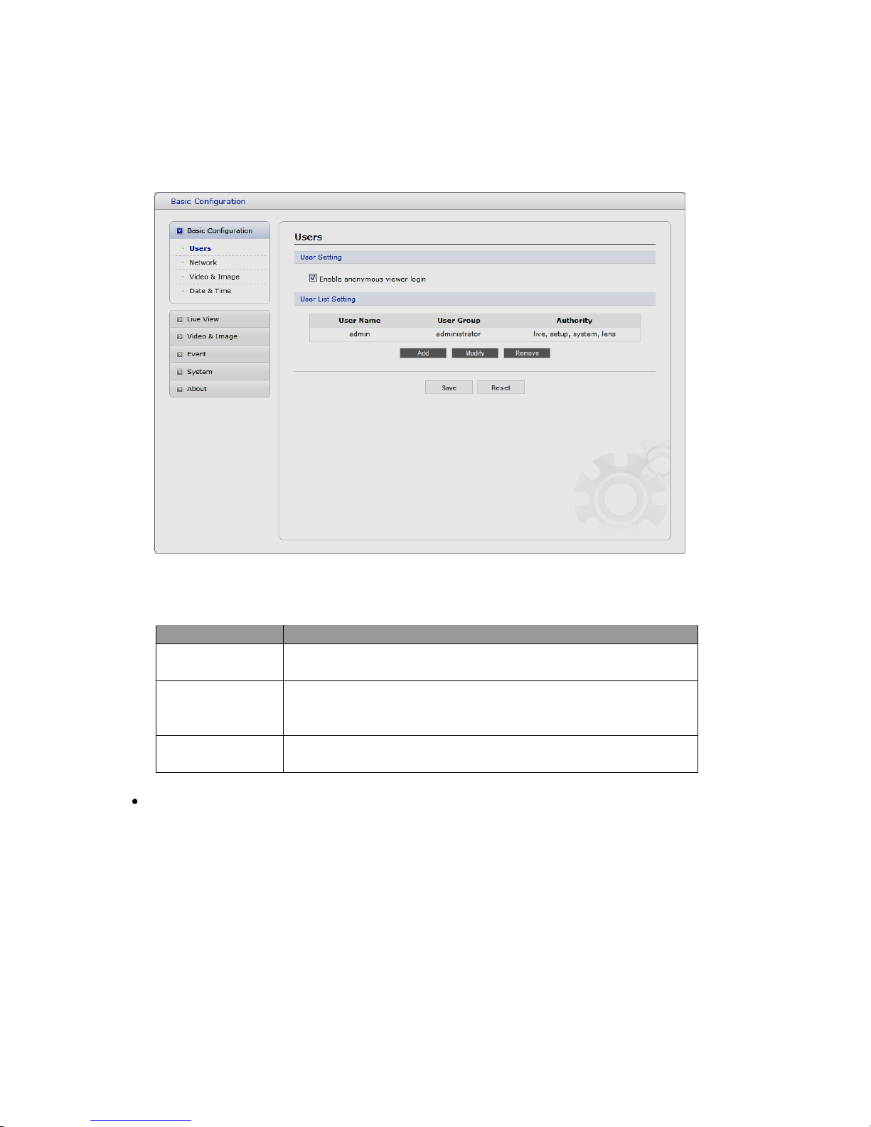
1) Users
User access control is enabled by default. An administrator can set up other users, by giving these
user names and passwords. It is also possible to allow anonymous viewer login, which means that
anybody may access the Live View page, as described below:
The user list displays the authorized users and user groups (levels):
User Group
Authority
Guest
Provides the lowest level of access, which only allows access to the
Live View page.
Operator
An operator can view the Live View page, create and modify
events, and adjust certain other settings. Operators have no access
to System Options.
Administrator
An administrator has unrestricted access to the Setup tools and can
determine the registration of all other users.
Enable anonymous viewer login: Check the box to use the webcasting features. Refer to
“3.5.2 Video & Image” for more details.
22
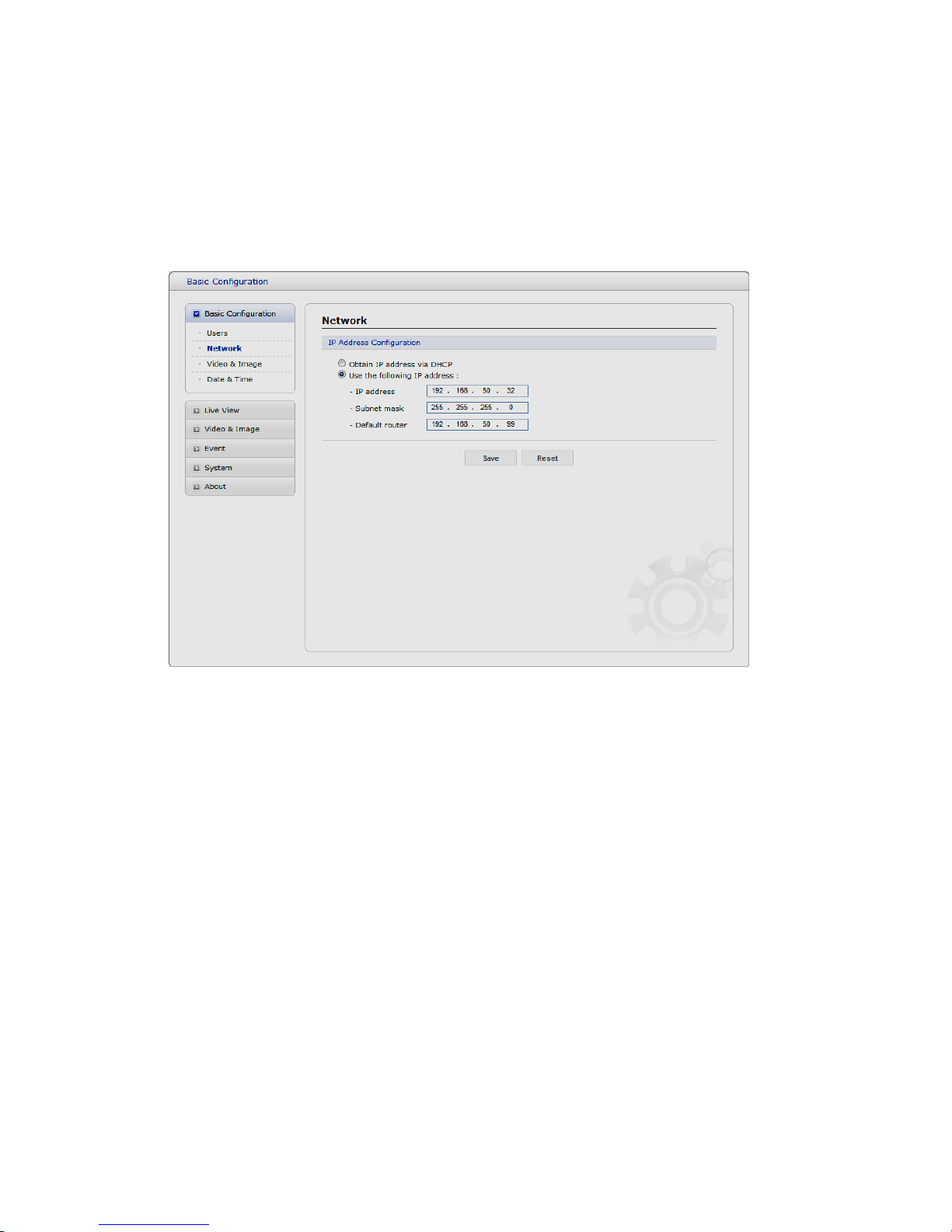
2) Network
The network camera supports both IP version 4 and IP version 6. Both versions may be enabled
simultaneously, and at least one version must always be enabled. When using IPv4, the IP address for
the network camera can be set automatically via DHCP, or a static IP address can be set manually.
If IPv6 is enabled, the network camera receive an IP address according to the configuration in the
network router. There is also the option of using the Internet Dynamic DNS Service. For more
information on setting the Network, please see Setup> System>Security>Network.
• Obtain IP address via DHCP - Dynamic Host Configuration Protocol (DHCP) is a protocol
that lets network administrators centrally manage and automate the assignment of IP
addresses on a network. DHCP is enabled by default. Although a DHCP server is mostly
used to set an IP address dynamically, it is also possible to use it to set a static, known IP
address for a particular MAC address.
• Use the following IP address - To use a static IP address for the Network Camera,
check the radio button and then make the following settings:
- IP address - Specify a unique IP address for your Network Camera.
- Subnet mask - Specify the mask for the subnet the Network Camera is located on.
- Default router - Specify the IP address of the default router (gateway) used for
connecting devices attached to different networks and network segments.
Notes:
1. DHCP should only be enabled if using dynamic IP address notification, or if your DHCP server can
update a DNS server, which then allows you to access the Network Camera by name (host name).
If DHCP is enabled and you cannot access the unit, you may have to reset it to the factory
default settings and then perform the installation again.
2. The ARP/Ping service is automatically disabled two minutes after the unit is started, or
as soon as an IP address is set.
3. Pinging the unit is still possible when this service is disabled.
23
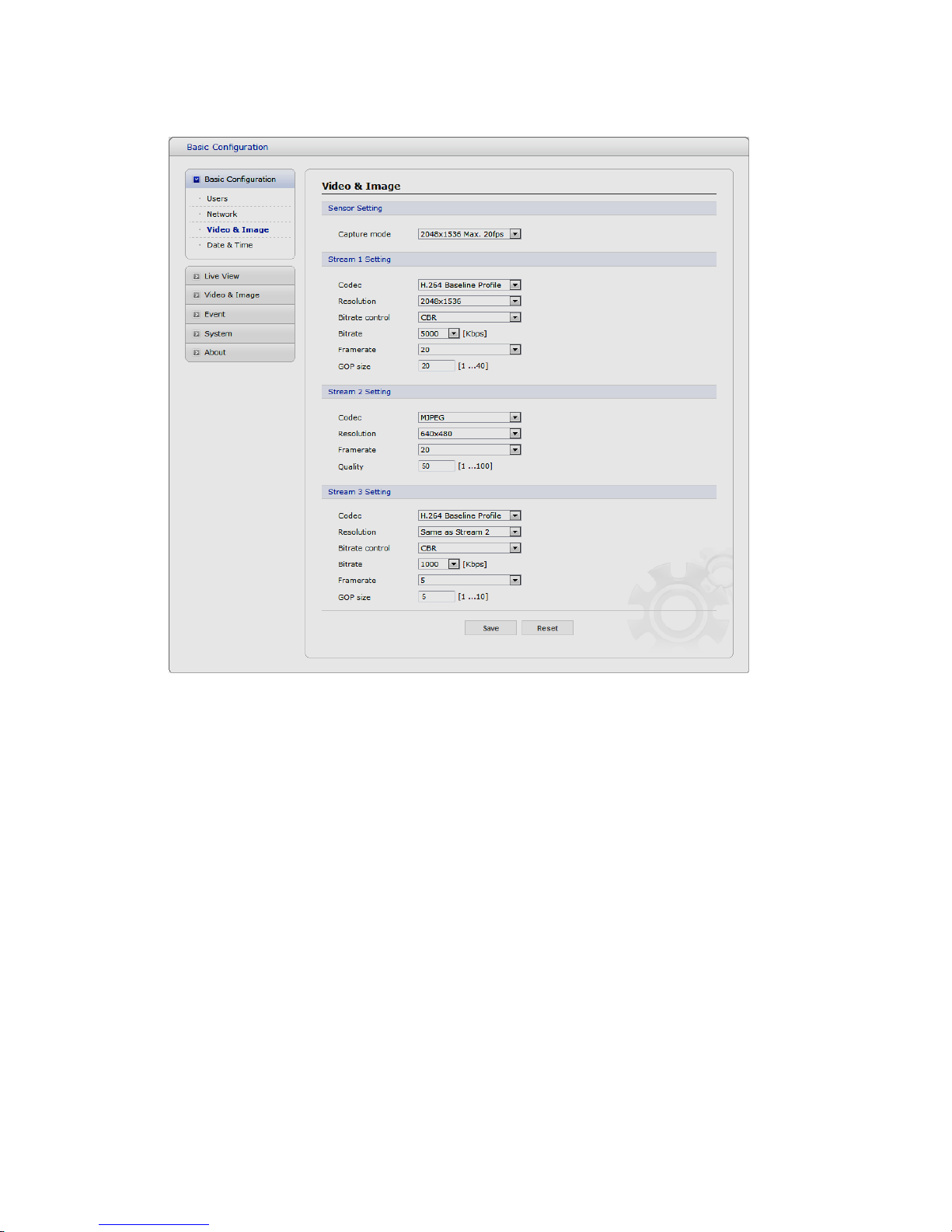
3) Video & Image
• Sensor Setting
- Capture Mode:
Choose Capture Mode you wish to use from the drop-down list:
* 2048x1536 Max 20fps: Capture resolution is 2048x1536 and Maximum frame is 20.
* 1920x1080 Max 30fps: Capture resolution is 1920x1080 and Maximum frame is 30.
• Stream1 Setting
- Codec:
The codec settings are separated into MPEG4 and H.264.
H.264 is also known as MPEG-4 Part 10. This is the new generation compression standard
for digital video. This function offers higher video resolution than Motion JPEG or MPEG-4 at
the same bit rate and bandwidth, or the same quality video at a lower bit rate.
There are 4 pre-programmed stream profiles available for quick set-up. Choose the form of
video encoding you wish to use from the drop-down list:
* H.264 HP(High Profile): The primary profile for broadcast and disc storage applications,
particularly for high-definition television applications (for example, this is the profile adopted
by the Blu-ray Disc storage format and the DVB HDTV broadcast service).
* H.264 MP(Main Profile):
Primarily for low-cost applications that requires additional error robustness, this profile is
used rarely in videoconferencing and mobile applications, it does add additional error
 Loading...