

Vista VK2-1080XVFD3V9F, VK2-1080XVFD3V9Fe User Manual
VK2-1080XVFD3V9F(e)
User Manual
Before You Begin
Read these instructions before installing or operating this product.
Note: This installation should be made by a qualified service person and should conform to local codes. This
manual provides installation and operation information. To use this document, you must have the following
minimum qualifications:
• A basic knowledge of CCTV systems and components
• A basic knowledge of electrical wiring and low-voltage electrical connections
Intended use
Only use this product for its designated purpose; refer to the product specification and user documentation.
Customer Support
For assistance in installing, operating, maintaining and troubleshooting this product refer to this document and
any other documentation provided. If you still have questions, please contact Norbain Technical Support and
Sales:
Norbain SD Ltd, 210 Wharfedale Road, IQ Winnersh, Wokingham, Berkshire RG41 5TP, England.
UK +44 (0) 118 912 5000
Note: You should be at the equipment and ready with details before calling Technical Support.
Conventions Used in this Manual
Boldface or button icons highlight command entries. The following WARNING, CAUTION and Note state-
ments identify potential hazards that can occur if the equipment is not handled properly:
* WARNING
Improper use of this equipment can cause severe bodily injury or equipment damage.
** CAUTION
Improper use of this equipment can cause equipment damage.
Note: Notes contain important information about a product or procedure.
This apparatus is manufactured to comply with the radio interference.
A Declaration of Conformity in accordance with the following EU standards has been made.
The manufacturer declares that the product supplied with this document is compliant the provisions of the EMC Directive 2004/108/EC, the CE Marking Directive 93/68 EEC and all associated amendments.
All lead-free products offered by the company comply with the requirements of the European
law on the Restriction of Hazardous Substances (RoHS) directive: 2011/65/EU, which means
our manufacture processes and products are strictly lead-free and without the hazardous substances cited in the directive.
The crossed-out wheeled bin mark symbolizes that within the European Union the product
must be collected separately at the product end-of-life. This applies to your product and any
peripherals marked with this symbol. Do not dispose of these products as unsorted municipal
waste.
* This symbol indicates electrical warnings and cautions.
* This symbol indicates general warnings and cautions.
NORBAIN SD LTD reserves the right to make changes to the product and specification of the product from
time to time without prior notice.
WARNINGS AND CAUTIONS:
To reduce the risk of fire or electric shock, do not insert any metallic objects through the ventilation grills or
other openings on the equipment.
2

CAUTION
RISK OF ELECTRIC SHOCK
DO NOT OPEN
WARNING: TO REDUCE THE RISK OF ELECTRIC SHOCK,
DO NOT REMOVE COVER (OR BACK).
NO USER-SERVICABLE PARTS INSIDE.
IMPORTANT SAFEGUARDS
1. Read these instructions.
2. Keep these instructions.
3. Heed all warnings.
4. Follow all instructions.
5. Do not use this apparatus near water.
6. Clean only with dry cloth.
7. Do not block any ventilation openings, Install in accordance with the manufacturers in-
structions.
8. Do not install near any heat sources such as radiators, heat registers, stoves, or other
apparatus (including amplifiers) that produce heat.
9. Do not defeat the safety purpose of the polarized or grounding-type plug, A polarized plug
has two blades with one wider than the other. A grounding type plug has two blades and
a third grounding prong. The wide blade or the third prong are provided for your safety, If
the provided plug does not fit into your outlet, consult an electrician for replacement of the
obsolete outlet.
10. Protect the power cord from being walked on or pinched particularly at plugs, convenience receptacles, and the point where they exit from the apparatus.
11. Only use attachments/accessories specified by the manufacturer.
12. Unplug this apparatus during lightning storms or when unused for long periods of time.
13. Refer all servicing to qualified service personnel. Servicing is required when the appa-
ratus has been damaged in any way, such as power-supply cord or plug is damaged, liquid
has been spilled or objects have fallen into the apparatus, the apparatus has been exposed
to rain or moisture, does not operate normally, or has been dropped.
14. CAUTION − THESE SERVICING INSTRUCTIONS ARE FOR USE BY QUALIFIED
SERVICE PERSONNEL ONLY. TO REDUCE THE RISK OF ELECTRIC SHOCK DO NOT
PERFORM ANY SERVICING OTHER THAN THAT CONTAINED IN THE OPERATING INSTRUCTIONS UNLESS YOU QRE QUALIFIED TO DO SO.
15. Use satisfy clause 2.5 of IEC60950-1/UL60950-1 or Certified/Listed Class 2 power
source only.
16. ITE is to be connected only to PoE networks without routing to the outside plant.
CE COMPLIANCE STATEMENT
WARNING
This is a Class A product. In a domestic environment this product may cause radio interference in which case the user may be required to take adequate measures.
CA
UTION
RISK
OF EXPLOSION IF BATTERY IS REPLACED BY AN INCORRECT TYPE.
DISPOSE
OF USED BATTERIES ACCORDING TO THE INSTRUCTIONS.
3

Contents
1 Introduction 5
1.1 Components . . . . . . . . . . . . . . . . . . . . . . . . . . . . . . . . . . . . 5
1.2 Key Features . . . . . . . . . . . . . . . . . . . . . . . . . . . . . . . . . . . . 6
2 Installation 7
2.1 Overview . . . . . . . . . . . . . . . . . . . . . . . . . . . . . . . . . . . . . . 7
2.2 Connection . . . . . . . . . . . . . . . . . . . . . . . . . . . . . . . . . . . . . 11
2.2.1 Network Connection & IP assignment . . . . . . . . . . . . . . . . . . 12
3 Operation 13
3.1 Access from a browser . . . . . . . . . . . . . . . . . . . . . . . . . . . . . . 13
3.2 Access from the internet . . . . . . . . . . . . . . . . . . . . . . . . . . . . . 14
3.3 Setting the admin password over a secure connection . . . . . . . . . . . . . 14
3.4 Live View Page . . . . . . . . . . . . . . . . . . . . . . . . . . . . . . . . . . . 15
3.5 Playback . . . . . . . . . . . . . . . . . . . . . . . . . . . . . . . . . . . . . . 17
3.6 Network Camera Setup . . . . . . . . . . . . . . . . . . . . . . . . . . . . . . 19
3.6.1 Basic Configuration . . . . . . . . . . . . . . . . . . . . . . . . . . . . 19
3.6.2 Live View . . . . . . . . . . . . . . . . . . . . . . . . . . . . . . . . . . 23
3.6.3 Video & Image . . . . . . . . . . . . . . . . . . . . . . . . . . . . . . . 24
3.6.4 Audio . . . . . . . . . . . . . . . . . . . . . . . . . . . . . . . . . . . . 33
3.6.5 Event . . . . . . . . . . . . . . . . . . . . . . . . . . . . . . . . . . . . 35
3.6.6 System . . . . . . . . . . . . . . . . . . . . . . . . . . . . . . . . . . . 58
3.7 Help . . . . . . . . . . . . . . . . . . . . . . . . . . . . . . . . . . . . . . . . . 79
3.8 Resetting to the factory default settings . . . . . . . . . . . . . . . . . . . . . 80
A Appendix 81
A.1 Troubleshooting . . . . . . . . . . . . . . . . . . . . . . . . . . . . . . . . . . . 81
A.2 Alarm Connection . . . . . . . . . . . . . . . . . . . . . . . . . . . . . . . . . 82
A.3 Preventive Maintenance . . . . . . . . . . . . . . . . . . . . . . . . . . . . . . 82
A.4 Product Specification . . . . . . . . . . . . . . . . . . . . . . . . . . . . . . . . 83
A.5 System Requirement for Web Browser . . . . . . . . . . . . . . . . . . . . . . 85
A.6 General Performance Considerations . . . . . . . . . . . . . . . . . . . . . . 85
4

1 Introduction
The network camera supports the network service for a sensor image with progressive scan,
which can be monitored on a real-time screen regardless of distances and locations. By using its dedicated program, many users are able to have an access to the network camera
at once or a single user can monitor various network cameras at the same time. It also
enables users to play, store and retrieve a monitoring image by using a PC. All the settings
and real-time monitoring screens are also provided through an access to the web.
The network camera is fully featured for security surveillance and remote monitoring needs.
It is based on the DSP compression chip, and makes it available on the network as real-time,
full frame rate Motion JPEG and H.264 video streams.
The alarm input and alarm output can be used to connect various third party devices, such
as, door sensors and alarm bells.
1.1 Components
This system comes with the following components;
Dome Camera · · · · · · · · · · · · · · · · · · · · · · · · 1
Installation Guide/CD · · · · · · · · · · · · · · · · · · · · · · · · 1
Template Sheet · · · · · · · · · · · · · · · · · · · · · · · · 1
Accessory Kit · · · · · · · · · · · · · · · · · · · · · · · · 1
Check your package to make sure that you received the complete system, including all
components listed above.
5

1.2 Key Features
• Brilliant video quality
The network camera offers the highly efficient H.264 video compression, which drastically reduces bandwidth and storage requirements without compromising image quality. Motion JPEG is also supported for increased flexibility.
• Wide Dynamic Range
The network camera provides true WDR (Wide Dynamic Range) that improves video
exposure quality in scenes with high contrast between bright and dark areas in the
video, for example a shady area and a sunny area in the same scene.
• Dual or Triple Streams
The network camera can deliver dual or triple video streams simultaneously at full
frame rate in all resolutions up to Full-HD (1920 x 1080p) using Motion H.264 and
JPEG. This means that several video streams can be configured with different compression formats, resolutions and frame rates for different needs.
• Image setting adjustment
The network camera also enables users to adjust image settings such as contrast,
brightness and saturation to improve images before encoding takes place.
• Intelligent video capabilities
The network camera includes intelligent capabilities such as enhanced video motion
detection. The network cameras external inputs and outputs can be connected to devices such as sensors and relays, enabling the system to react to alarms and activate
lights or open/close doors.
• Improved Security
The network camera logs all user access, and lists currently connected users. Also, its
full frame rate video can be provided over HTTPS.
• PoE (Power over Ethernet)
This network camera can be powered through PoE (IEEE802.3af), which simplifies
installation since only one cable is needed for carrying power, as well as video controls.
• ONVIF Certificate
This is a global interface standard that makes it easier for end users, integrators, consultants, and manufacturers to take advantage of the possibilities offered by network
video technology. ONVIF enables interoperability between different vendor products,
increased flexibility, reduced cost, and future-proof systems.
• Micro-SD Recording support
The Network Camera also supports a micro-SD memory slot for local recording with
removable storage.
• Audio support
The Network Camera also supports two-way audio.
6
2 Installation
For the operation of the Network Camera, it is necessary to connect a network cable for
data transmission, power connection from supplied power adapter. Depending on operation
methods, it is possible to connect an alarm cable additionally. For its fixation on different
locations, please consult with an installer.
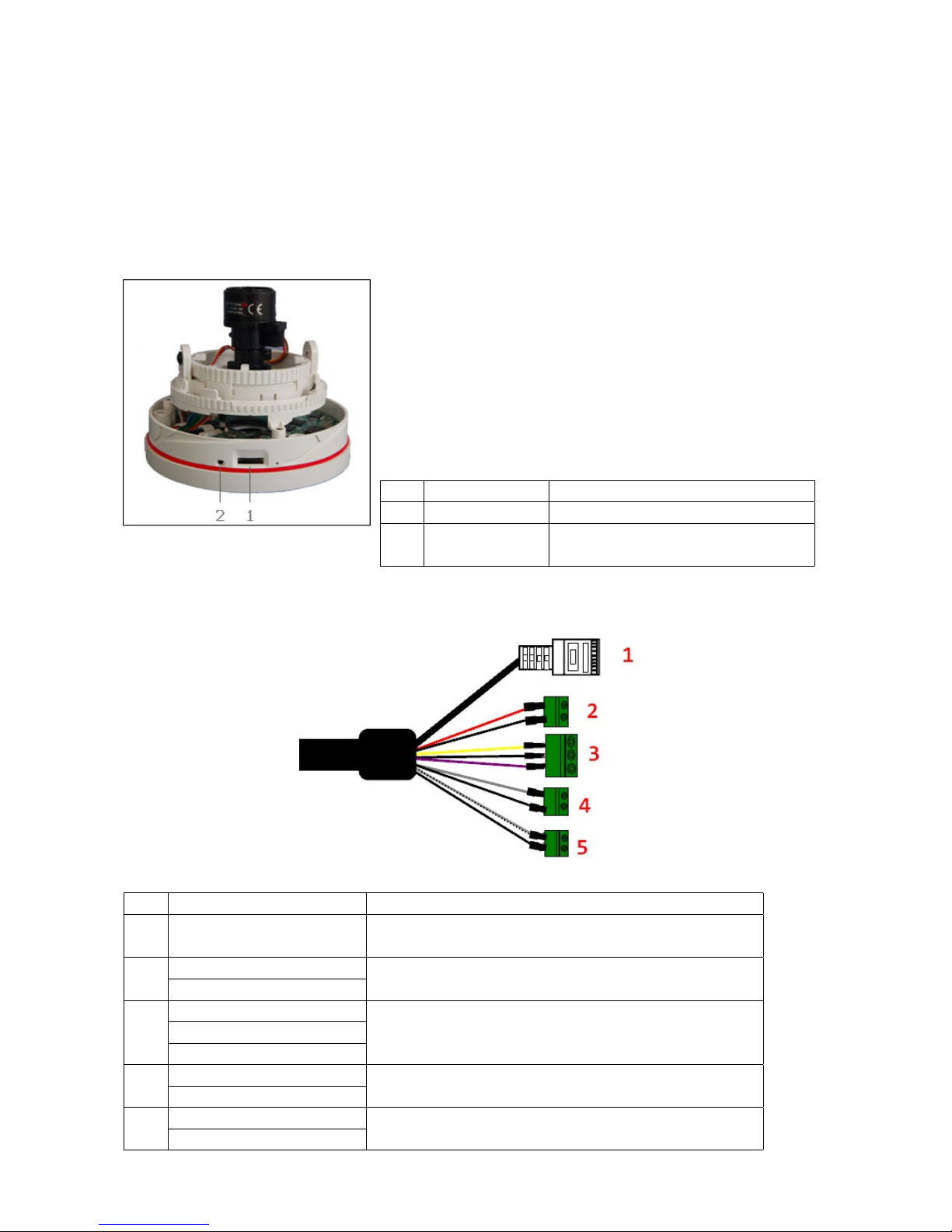
2.1 Overview
NO Name Description
1 Micro SD Slot Micro SD slot for local recording
2 Status LED
Amber : On System Booting
Green : Normal Operation
• Extension Cable
NO Wire Color Description
1 Black
Ethernet, RJ-45 port compatible
with 10/100Mbps PoE Modular Jack
2
Red: DC12V
Main Power, 2pin terminal, DC12V 450mA(4.4W)
White: GND
3
Yellow: Alarm In
Alarm input and output, 3pin terminalBlack: GND
Violet: Alarm Out
4
Grey: Audio In
Audio line input, 2pin terminal
Black: GND
5
White/Black: Audio Out
Audio line output, 2pin terminal
Black: GND
7

• Installing & Adjusting Camera Module
To mount the board camera on the camera mount bracket, place the four board camera supports on the four slot holes near the front and the rear of the camera mount bracket.
Note: Arrow mark indicates the top of the camera image.
Use the following drawings to install the camera module to the housing.
8
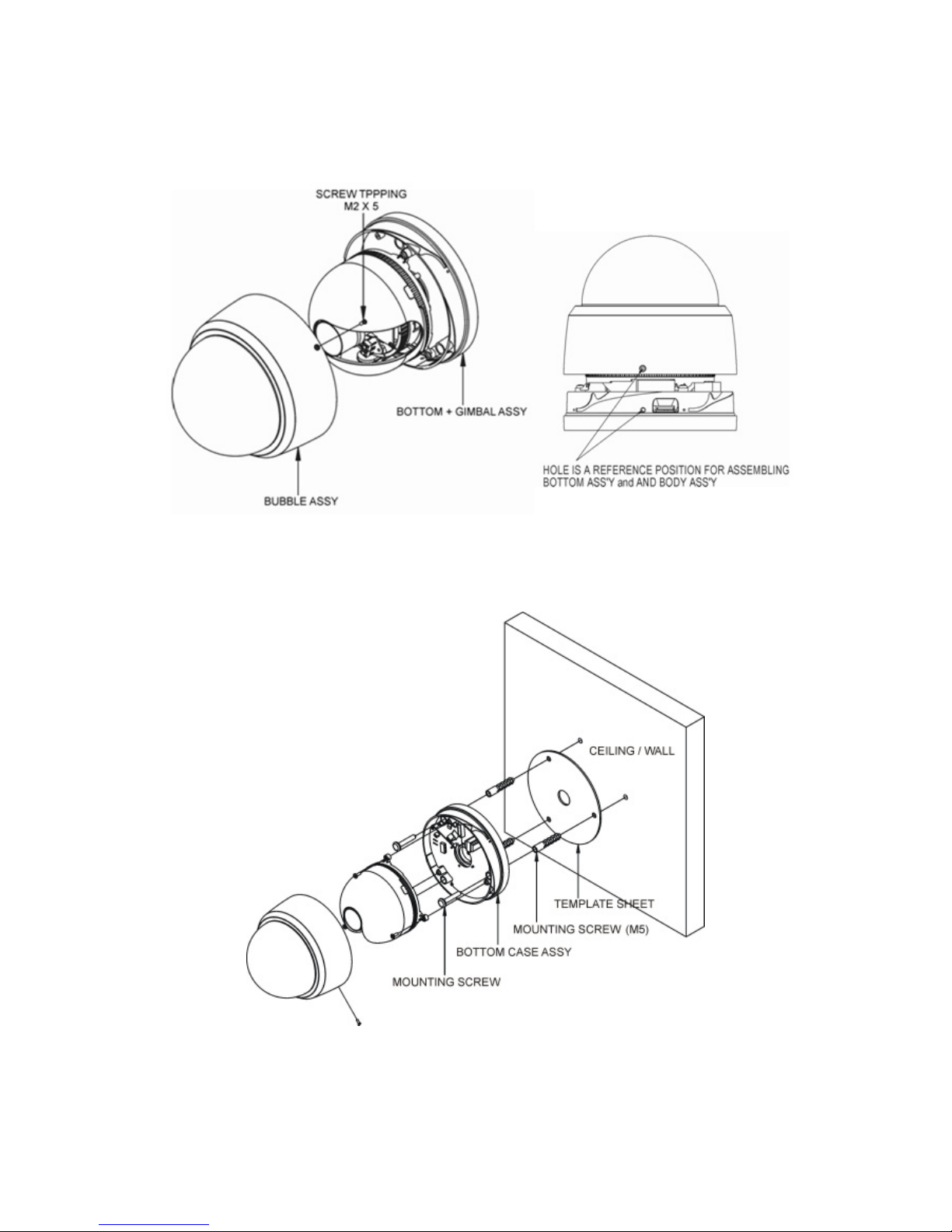
• Base Installation
Make mounting holes and cable hole in the place (ceiling) to which this dome. Camera is
installed using the Template sheet.
To remove dome cover, turn the dome cover counterclockwise until locators reach end of
travel and pull off. Push the liner in the direction of the arrow (three OPEN marks) and pull it
out.
Fasten Mounting screws(2X) and align the dome camera with it like above picture. Turn the
dome camera to left direction about 16 degree.
The assembly of the dome window cover and liner is in reverse order of disassembly Finally,
lock dome window cover with locking screw(M2X4) from the accessory kit.
9
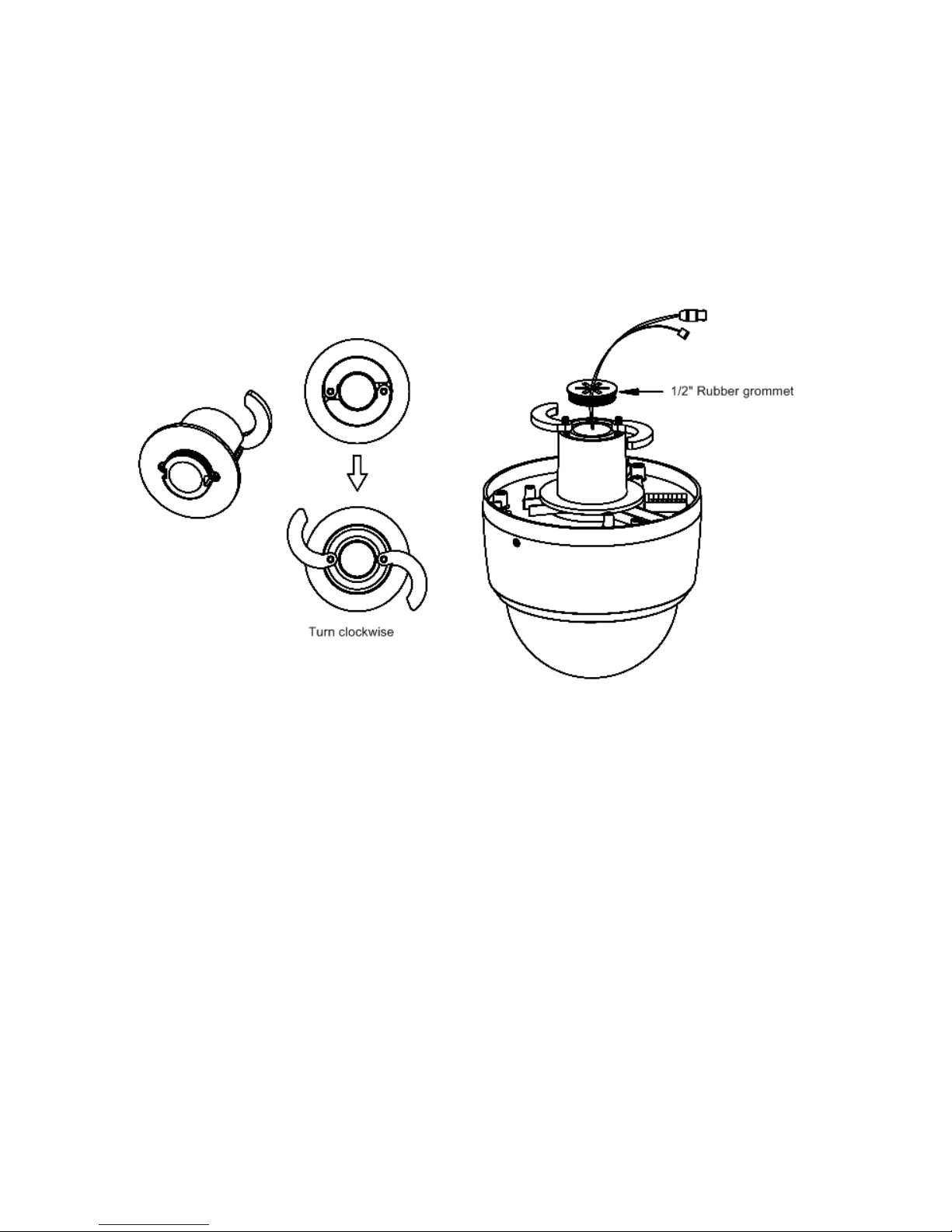
• Using the Quick install Adaptor (option)
Use the optional Quick install Adaptor on wall or ceiling application
1. Install the Adaptor into the mounting surface and use the screws to adjust the position
of the two locking arms on the Quick Install Adaptor
2. Push the cables through the opening and 1/2 hole grommet
3. Make sure the grommet is property installed on the adaptor to prevent dust ingress
10

2.2 Connection
• Micro SD memory slot on the Board
Card Slot for Micro SD memory: Socket J15
• Connecting to the RJ-45
Connect a standard RJ-45 cable to the network port of the network camera. Generally
a cross-over cable is used for directly connection to PC, while a direct cable is used for
connection to a hub. You can also use a router featuring PoE (Power over Ethernet) to
supply power to the camera.
• Connecting Alarms
AI(Alarm In): You can use external devices to signal the network camera to react on
events. Mechanical or electrical switches can be wired to the AI (Alarm In) and G
(Ground) connectors.
G(Ground): Connect the ground side of the alarm input and/or alarm output to the G
(Ground) connector.
AO(Alarm Out): The network camera can activate external devices such as buzzers
or lights. Connect the device to the AO (Alarm Out) and G (Ground) connectors.
• Connecting the Power
Connect the power of 12 VDC 450mA for the network camera. Connect the positive
(+) pole to the + position and the negative (-) pole to the - position for the DC power.
– Be careful not to reverse the polarity when connecting the power cable.
– A router featuring PoE (Power over Ethernet) can also be used to supply power to
the camera.
– For the power specifications, refer to the Appendix, Product Specification.
– If PoE and 12 VDC are both applied, the camera will be supplied with power from
PoE.
11
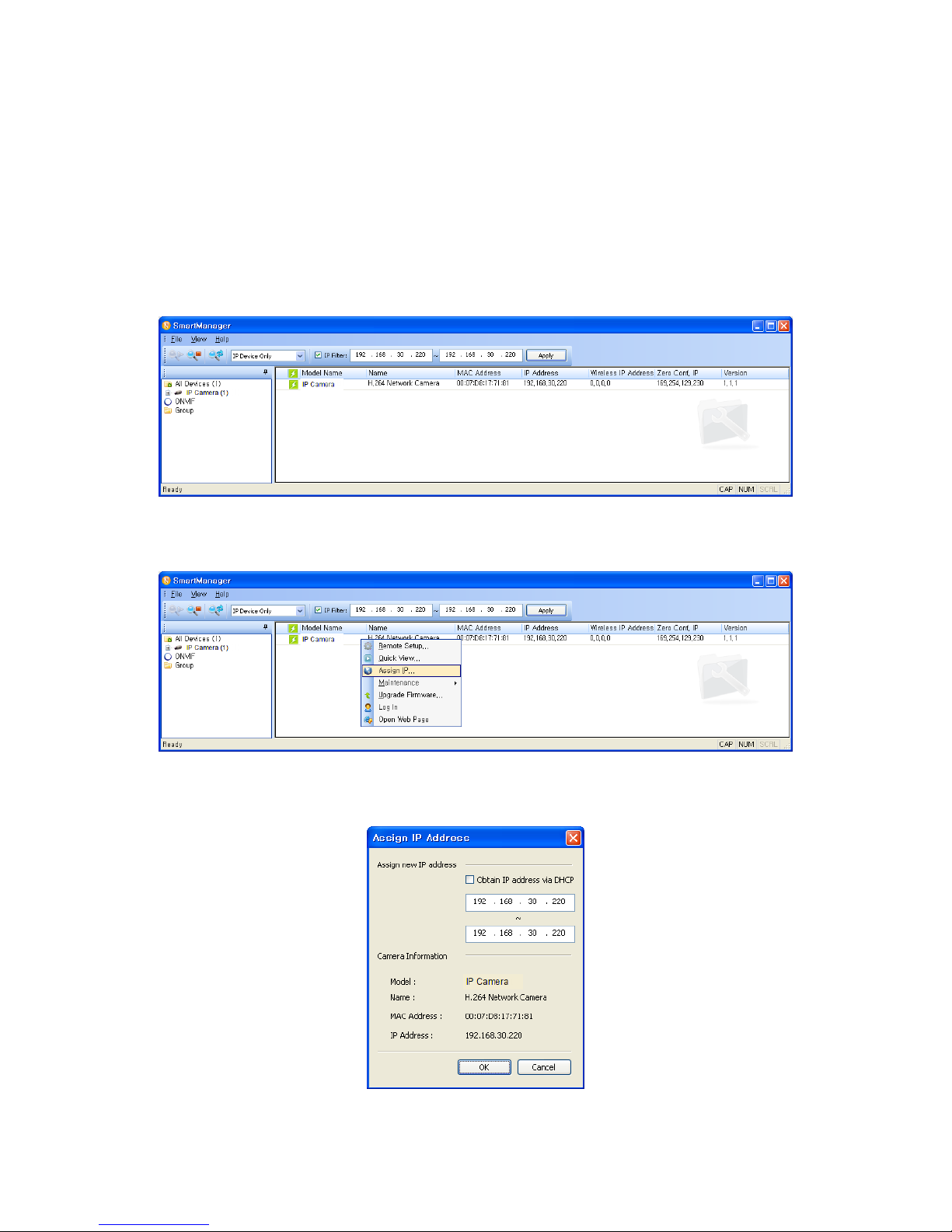
2.2.1 Network Connection & IP assignment
The camera supports the operation through the network. When a camera is first connected
to the network, it is necessary to allocate an IP address to the device with the SmartManager
utility on the CD. (Default IP 192.168.30.220)
1) Connect the network camera/device to the network and power up.
2) Start SmartManager utility (Start > All programs > SmartManager > SmartManager).
The main window will display, and after a short while any network devices connected to the
network will be displayed in the list.
3) Select the camera on the list and click right button of the mouse. You can see the pop-up
menu as below.
4) Select Assign IP Address. The Assign IP window will display. Enter the required IP address.
NOTE: For more information, refer to the SmartManager Users Manual.
12
3 Operation
The network camera can be used with Windows operating system and browsers. The recommended browsers are Internet Explorer, Safari, Firefox, Opera and Google Chrome with
Windows.
NOTE: To view streaming video in Microsoft Internet Explorer, set your browser to allow
ActiveX controls.
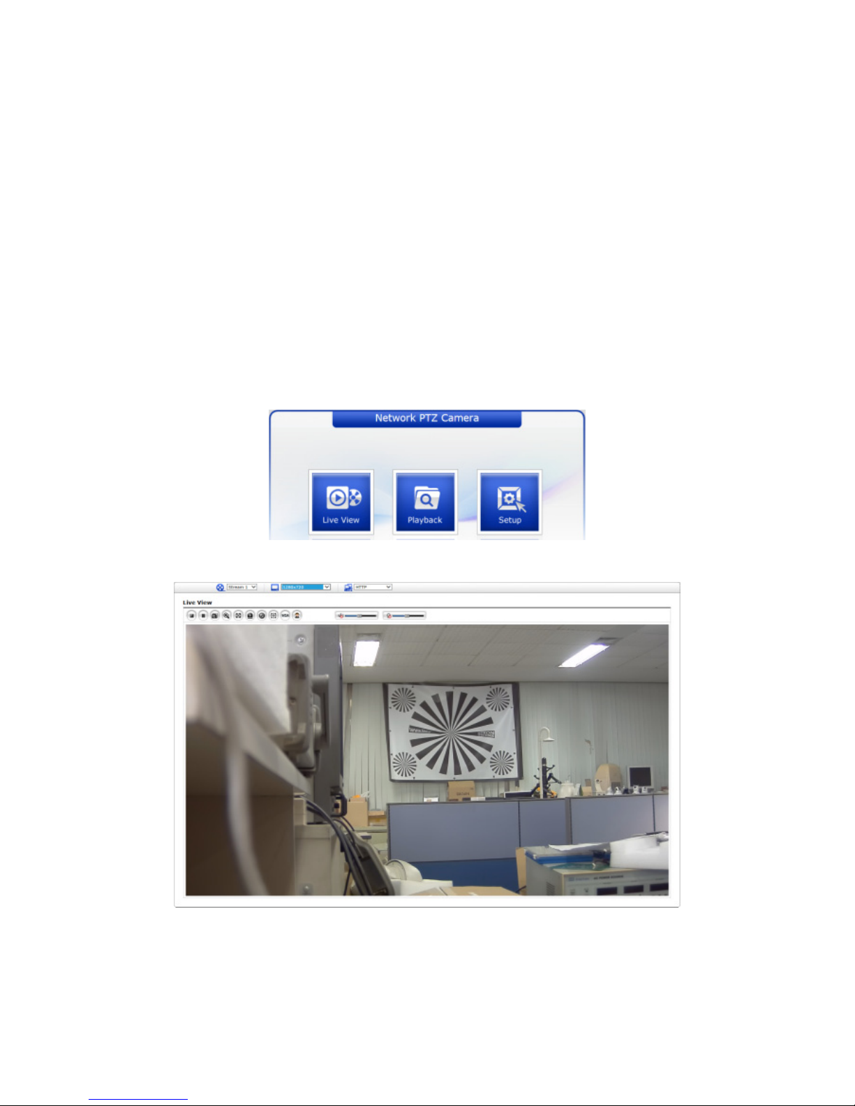
3.1 Access from a browser
1. Start a browser (Internet Explorer).
2. Enter the IP address or host name of the network camera in the Location/Address field
of your browser.
3. You can see a starting page. Click Live View, Playback, or Setup to enter web page.
4. The network cameras Live View page appears in your browser.
13

3.2 Access from the internet
Once connected, the network camera is accessible on your local network (LAN). To access
the network camera from the Internet you must configure your broadband router to allow
incoming data traffic to the network camera. To do this, enable the NAT traversal feature,
which will attempt to automatically configure the router to allow access to the network camera. This is enabled from Setup > System > Network > NAT. For more information, please
see ”3.5.7 System > Network > NAT” of User’s Manual.
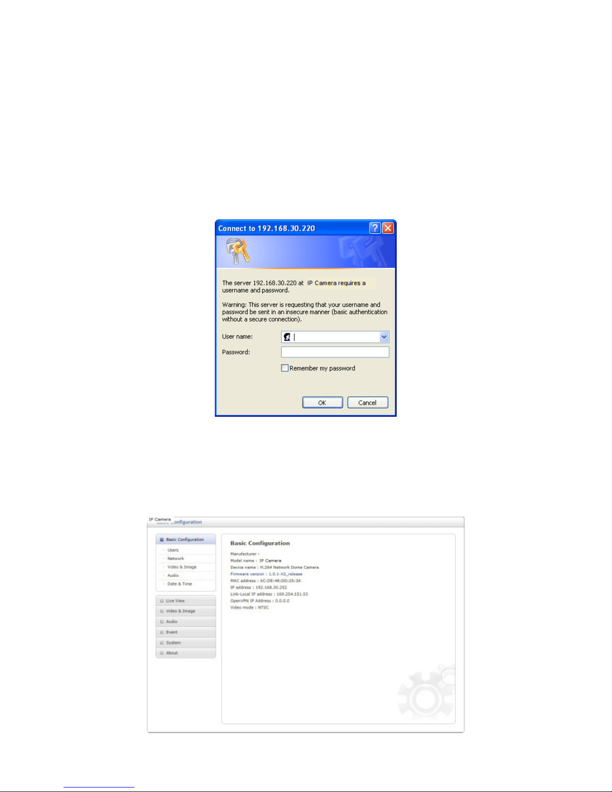
3.3 Setting the admin password over a secure connection
To gain access to the product, the password for the default administrator user must be set.
This is done in the Admin Password dialog, which is displayed when the network camera is
accessed for the setup at the first time. Enter your admin name and password, set by the
administrator.
NOTE: The default administrator user name and password is admin. If the password is lost,
the network camera must be reset to the factory default settings. Please see Resetting to
the factory default settings.
To prevent network eavesdropping when setting the admin password, this can be done via
an encrypted HTTPS connection, which requires an HTTPS certificate (see NOTE below).
To set the password via a standard HTTP connection, enter it directly in the first dialog shown
below. To set the password via an encrypted HTTPS connection, please see 3.5.7 System
> Security > HTTPS of User’s Manual.
NOTE: HTTPS (Hypertext Transfer Protocol over SSL) is a protocol used to encrypt the
traffic between web browsers and servers. The HTTPS certificate controls the encrypted
exchange of information.
14
3.4 Live View Page
The Live View page comes in several screen modes: 1920x1080, 1280x1024, 1280x720(960),
1024x768, 704x480(576), 640x480(360) and 320x240. Users are allowed to select the most
suitable one out of those modes. Adjust the mode in accordance with your PC specifications
and monitoring purposes.
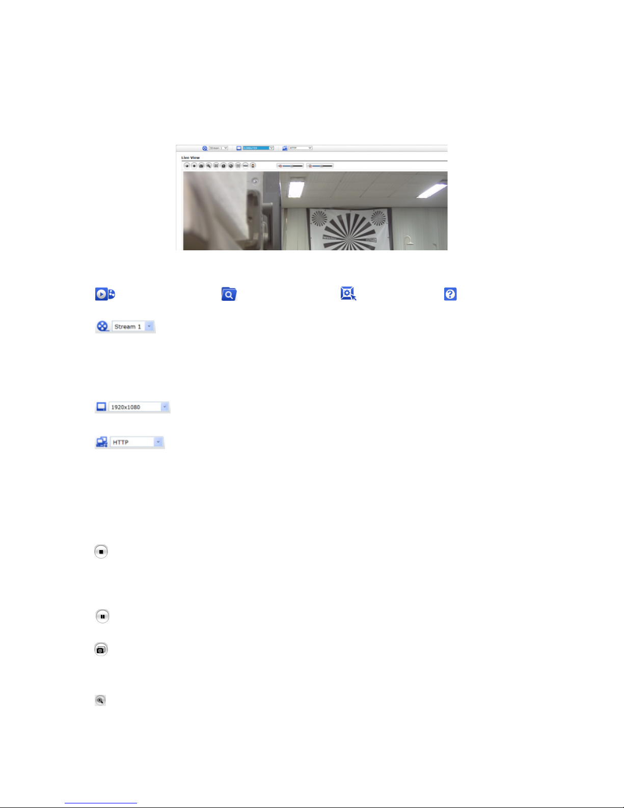
1) General controls
Live View Page Playback Page Setup Page Help Page
The video drop-down list allows you to select a customized or preprogrammed video stream on the Live View page. Stream profiles are configured under Setup > Basic Configuration > Video & Image. For more information, please see ”3.5.1 Basic Configuration > Video & Image” of Users
Manual.
The resolution drop-down list allows you to select the most suitable one
out of video resolutions to be displayed on Live View page.
The protocol drop-down list allows you to select which combination of protocols and methods to use depending on your viewing requirements, and
on the properties of your network.
2) Control toolbar
The live viewer toolbar is available in the web browser page only. It displays the following
buttons:
The Stop button stops the video stream being played. Pressing the key again toggles
the start and stop. The Start button connects to the network camera or starts playing
a video stream.
The Pause button pauses the video stream being played.
The Snapshot button takes a snapshot of the current image. The location where the
image is saved can be specified.
The Digital Zoom button activates a zoom-in or zoom-out function for video image on
the live screen.
15
The Full Screen button causes the video image to fill the entire screen area. No other
windows will be visible. Press the ’Esc’ button on the computer keyboard to cancel full
screen view.
The Manual Trigger button activates a pop-up window to manually start or stop the
event.
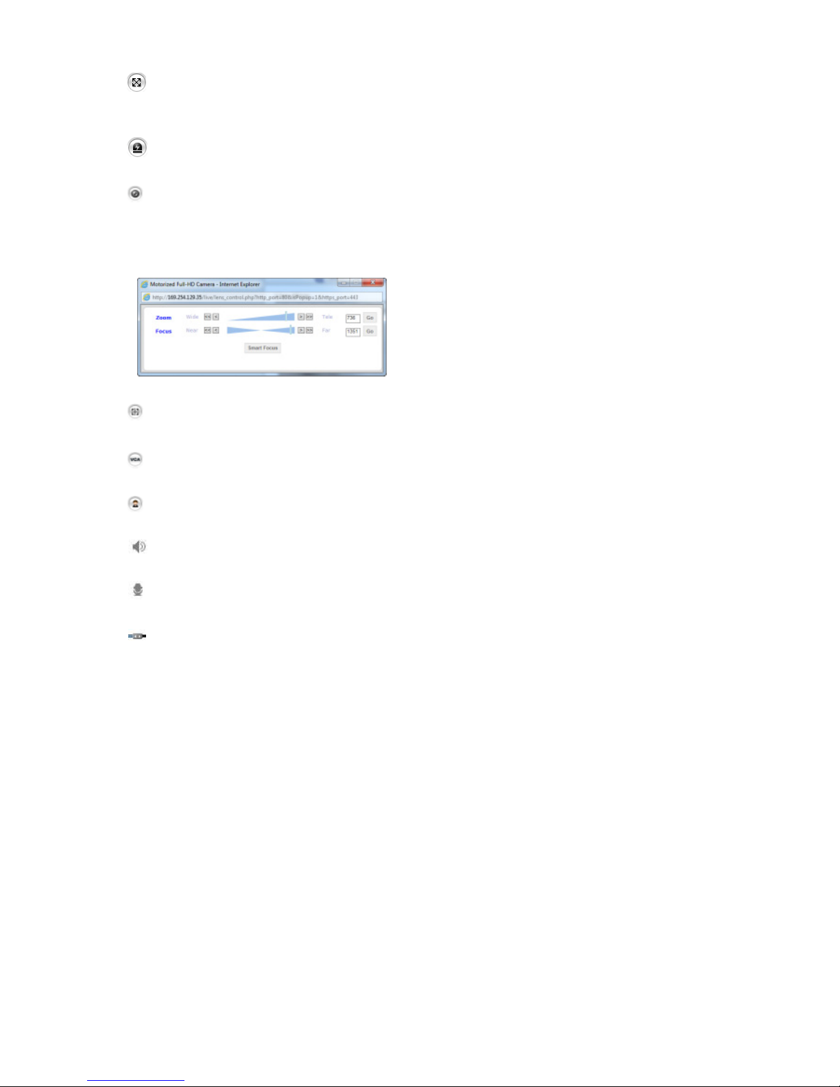
The Lens Control button allows user to control Zoom and Focus manually. (This Icon
appears for motorized lens model only.)
• Zoom: Click ”<<” or ”<” button to zoom out
and click ”>>” or ”>” button to zoom in. The
focus is moved slightly after adjusting zoom;
adjust the focus again, as necessary.
• Focus: Click ”<<” or ”<” button for far focus
and click ”>>” or ”>” button to near focus.
The Smart Focus button activates smart focus function which set the focus to the
optimum position. (This Icon appears for motorized lens model only.)
The VCA button shows/hides VCA rule setting and detected objects.
The Face Detection button shows/hides detected faces.
The Speaker button activates/deactivates external speaker.
The Mic button activates/deactivates microphone input.
Use this scale to control the volume of the speakers and microphones.
NOTE: VCA and Face Detection works exclusively to each other.
3) Video Streams
The network camera provides several images and video stream formats. Your requirements and the properties of your network will determine the type you use.
The Live View page in the network camera provides access to H.264 and Motion JPEG
video streams, and to the list of available video streams. Other applications and clients
can also access these video streams/images directly, without going via the Live View
page.
16
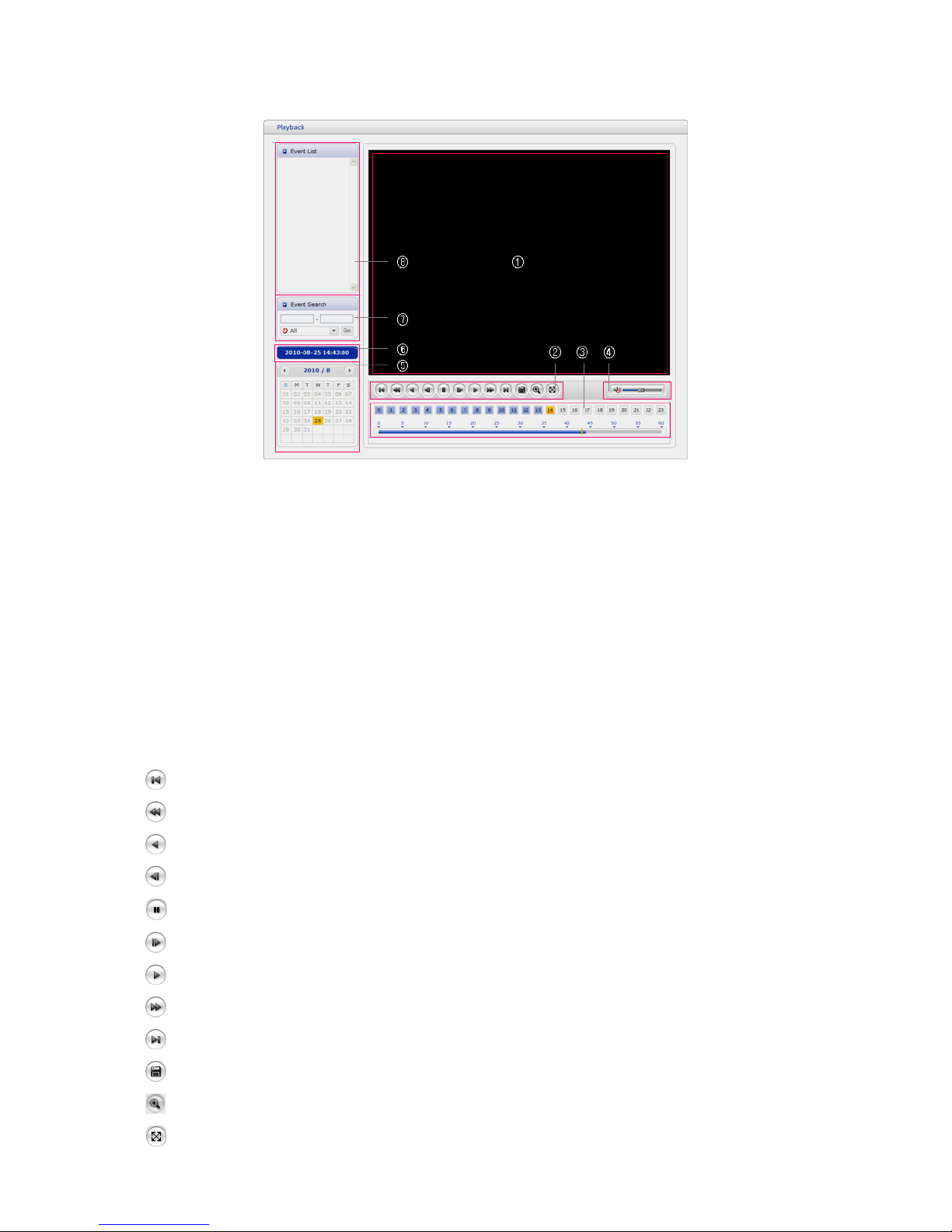
3.5 Playback
The Playback window contains a list of recordings made to the memory card. It shows each
recording’s start time, length, the event type used to start the recording, calendar and time
slice bar indicates if the recording is existed or not.
The description of playback window follows.
(1) Video Screen
You can see the video screen when playing the video clip in the Micro SD memory.
(2) Playback Buttons
To view a recording data in the SD local storage, select it from the list and click the
Playback buttons.
Go to the first: go to the beginning of the video clip.
Fast backward play: fast play backward of the video clip.
Backward play: play backward of the video clip.
Step backward play: go back one frame of the video clip.
Pause: pause playback of the video clip.
Step forward play: go forward one frame of the video clip.
Forward Play: play forward the video clip.
Fast forward play: play fast forward of the video clip.
Go to the last: go to the end of the video clip.
Clip copy: copy the video clip.
Zoom In: zoom in the video clip.
Full Screen: display full screen of the video.
17
(3) Time Chart
Display an hour-based search screen for the chosen date. If there is recording data, a
blue section will be displayed on a 24-hour basis. If you select a particular hour in the
chart, a yellow square on the hour will be displayed.
(4) Speaker Control Bar
Use this scale to control the volume of the speakers.
(5) Search Calendar
Search results from the SD local storage in the network camera connected are displayed
monthly. If there is a recorded data for a particular date, a blue square on the date will be
displayed. If you select a particular date in the calendar, a yellow square on the date will
be displayed.
(6) Play Time
Displays time of the video playing.
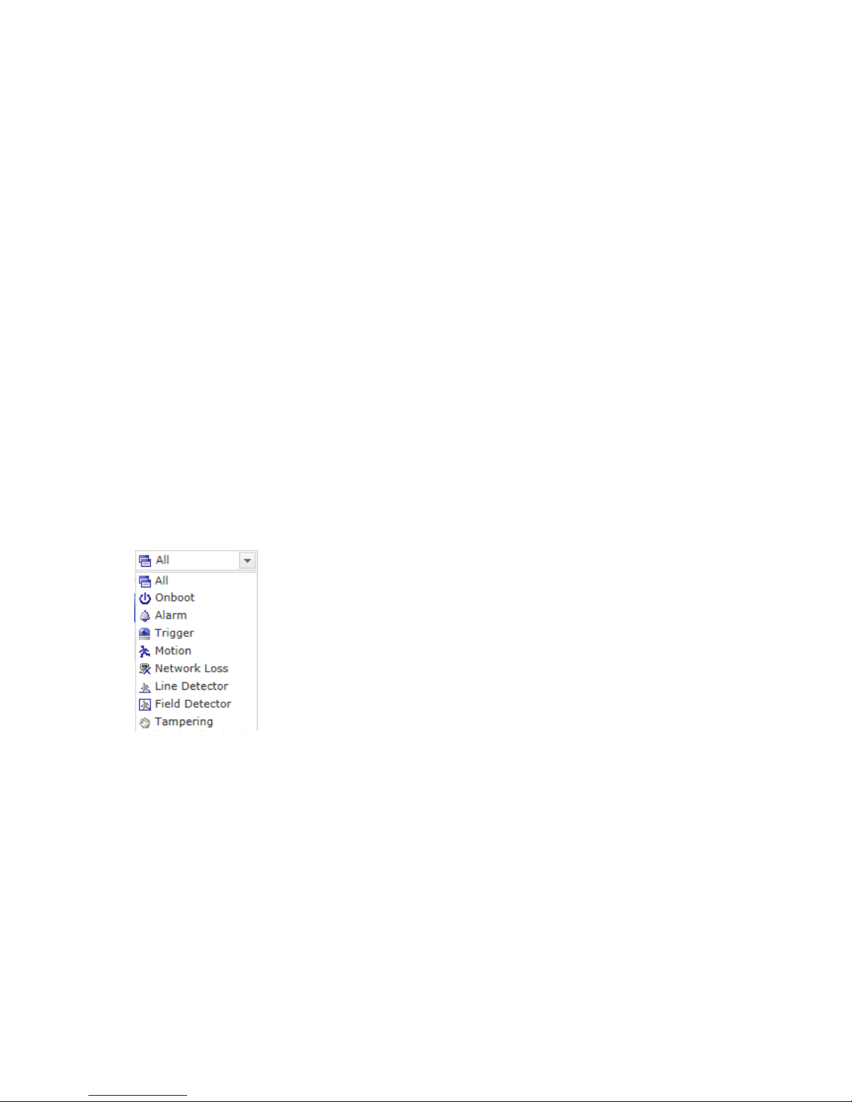
(7) Event Search Window
Select a search option in the drop-down list and click GO button. You can also enter
the time period for searching. If you click Start Date or End Date zone, displays Search
Calendar.
(8) Event List Window
Event List displays the event(s) that were recorded in the SD local storage. Select a list
and click the play button. The video clip will be played.
18
3.6 Network Camera Setup
This section describes how to configure the network camera.
Administrator has unrestricted access to all the Setup tools, whereas Operators have access
to the settings of Basic Configuration, which are Live View, Video & Image, Audio, Event,
Dome Configuration, and System.
You can configure the network camera by clicking Setup either in the first connection page
or the top second-right button of the Live View page. Accessing the network camera from a
computer for the first time opens the Admin Password dialog box. Enter your administrator
or operator id and password to get into setup page.
NOTE: If the password is lost, the network camera must be reset to the factory default
settings. Please see ”Resetting to the Factory Default Setting”.
3.6.1 Basic Configuration
You can see the device information in this information page.
19
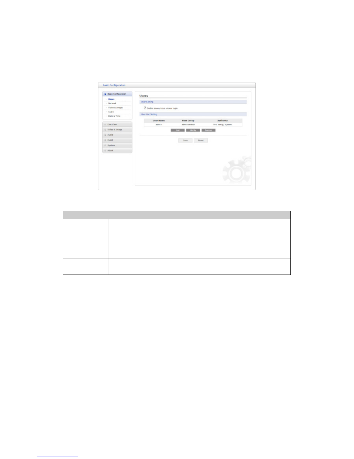
1) Users
User access control is enabled by default. The administrator can set up other users, by
giving user names and passwords. It is also possible to allow anonymous viewer login,
which means that anybody may access the Live View page, as described below:
The user list displays the authorized users and user groups (levels):
User Group Authority
Guest
Provides the lowest level of access, which only allows access
to the Live View page.
Operator
An operator can view the Live View page, create and modify
events, and adjust certain other settings. Operators have no
access to System Options.
Administrator
An administrator has unrestricted access to the Setup tools
and can determine the registration of all other users.
• Enable anonymous viewer login: Check the box to use the webcasting features. Re-
fer to ”3.5.3 Video & Image 3) Webcasting” for more details.
Please refer to ”3.5.7 System 2) Security Users” for more details about User setup.
20
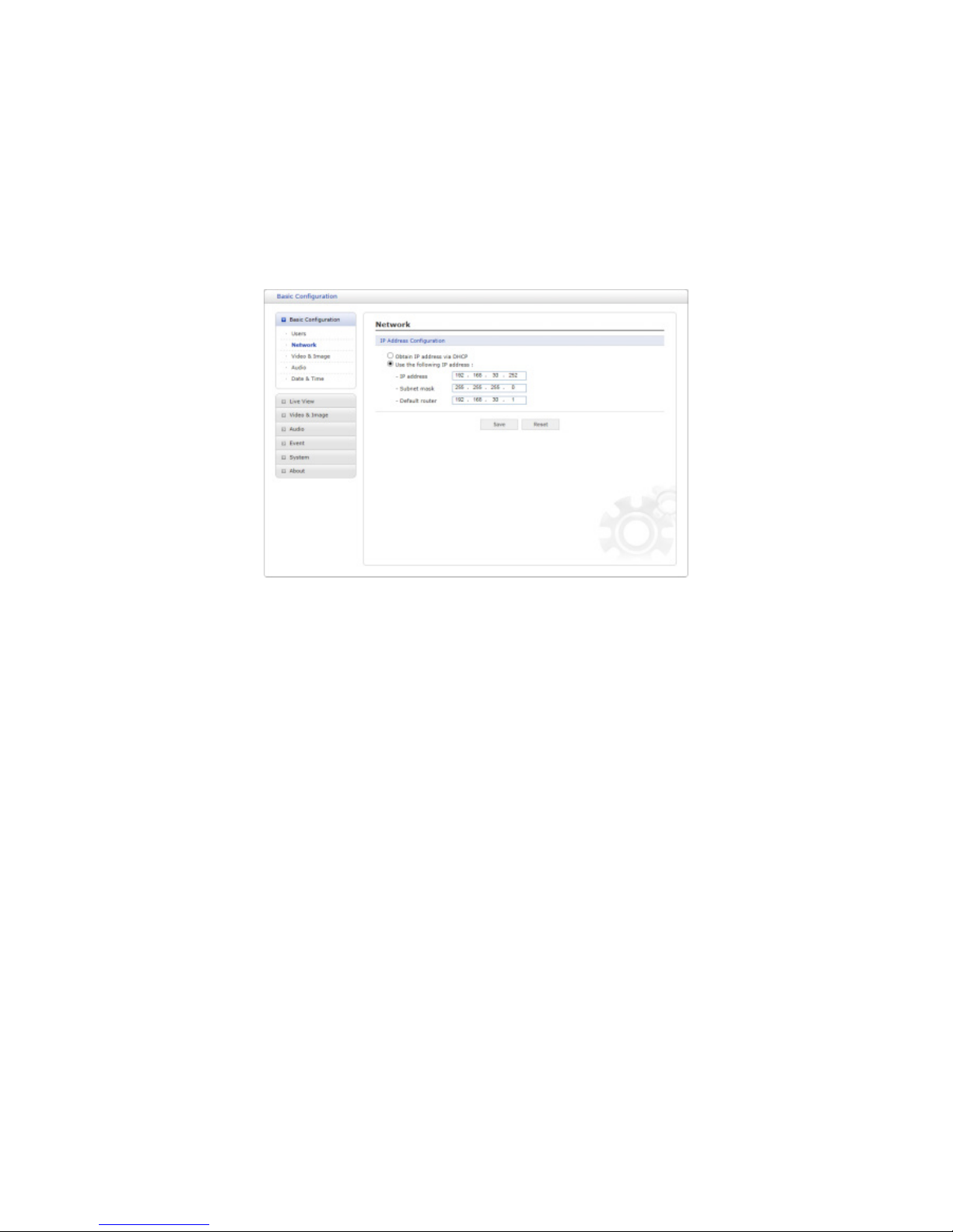
2) Network
The network camera supports both IP version 4 and IP version 6. Both versions may be
enabled simultaneously, and at least one version must always be enabled. When using
IPv4, the IP address for the network camera can be set automatically via DHCP, or a static
IP address can be set manually. If IPv6 is enabled, the network camera receives an IP address according to the configuration in the network router. There is also an option of using
the Internet Dynamic DNS Service. For more information on setting the network, please see
”System > Network > Basic”.
• Obtain IP address via DHCP: Dynamic Host Configuration Protocol (DHCP) is a pro-
tocol that lets network administrators centrally manage and automate the assignment
of IP addresses on a network. DHCP is enabled by default. Although a DHCP server
is mostly used to set an IP address dynamically, it is also possible to use it to set a
static, known IP address for a particular MAC address.
• Use the following IP address: To use a static IP address for the network camera,
check the radio button and then make the following settings:
– IP address: Specify a unique IP address for your network camera.
– Subnet mask: Specify the mask for the subnet the network camera is located on.
– Default router: Specify the IP address of the default router (gateway) used for
connecting devices attached to different networks and network segments.
NOTES:
1. DHCP should only be enabled if using dynamic IP address notification, or if your DHCP
server can update a DNS server, which then allows you to access the network camera
by name (host name). If DHCP is enabled and you cannot access the unit, you may
have to reset it to the factory default settings and then perform the installation again.
2. The ARP/Ping service is automatically disabled two minutes after the unit is started, or
as soon as an IP address is set.
3. Pinging the unit is still possible when this service is disabled.
Please refer to ”System > Network > Basic” for more details about Network setup.
21
3) Video & Image
User can setup and change setting of individual video stream in this page.
Please refer to ”Video & Image > Basic” for more details about Video & Image setup.
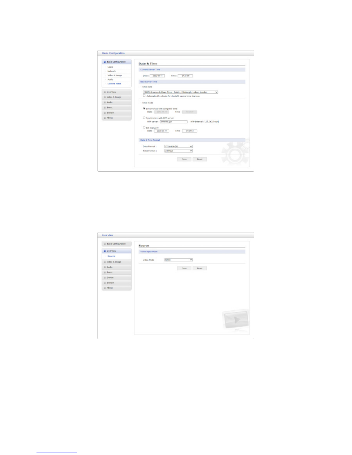
4) Audio
The network camera can transmit audio to other clients using an external microphone and
can play audio received from other clients by attaching a speaker. User can setup and
change setting of Audio in this page.
Please refer to ”Audio” for more details about Audio setup.
22
5) Date & Time
User can set time directly or assign time server to get the current time, as well as determine
Date & Time format in this page.
Please refer to ”System > Date & Time” for more details about Date & Time setup.
3.6.2 Live View
• Video Input Mode:
– Video Mode: Choose Video Mode you wish to use from the drop-down list: NTSC
or PAL
NOTE: This function may not be applicable, depending on the model.
23
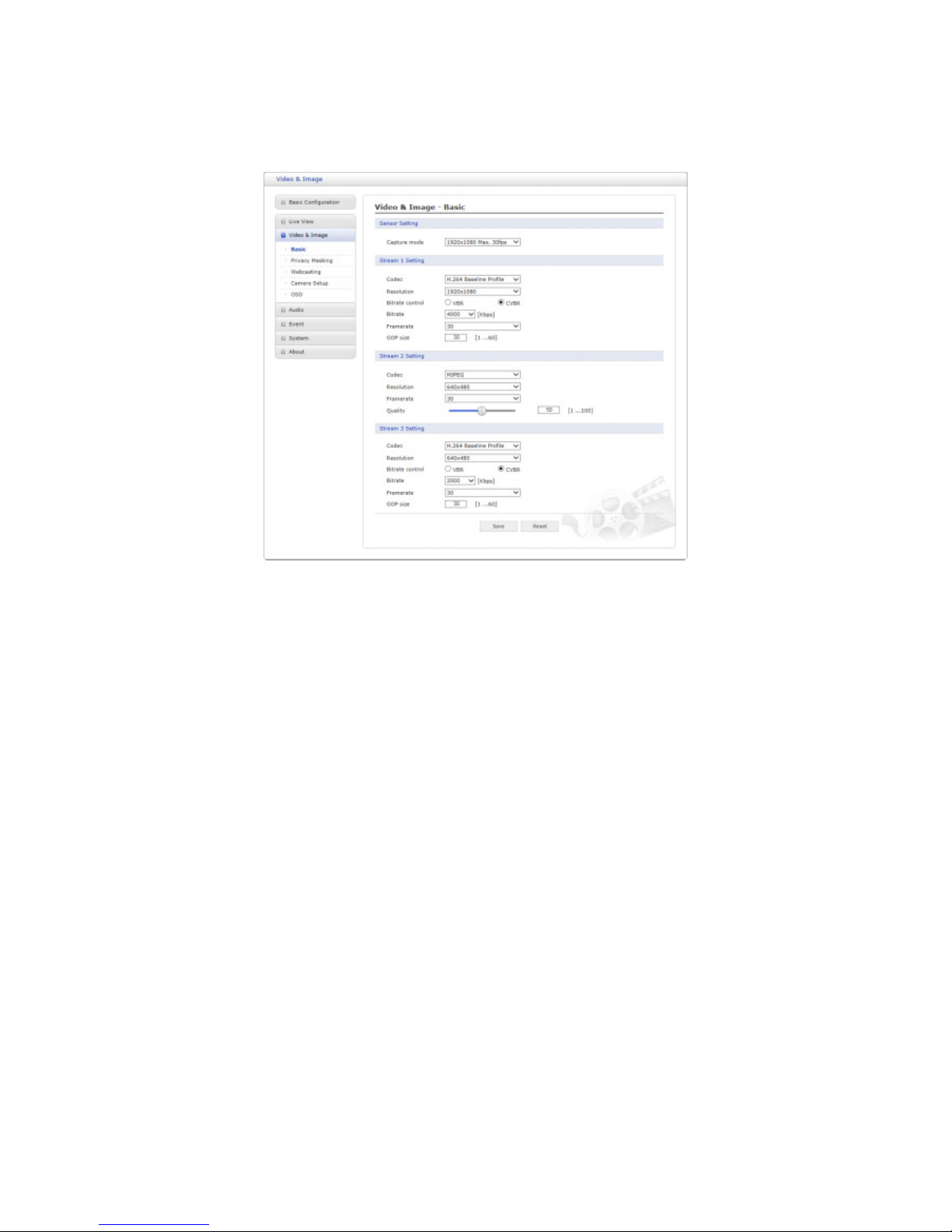
3.6.3 Video & Image
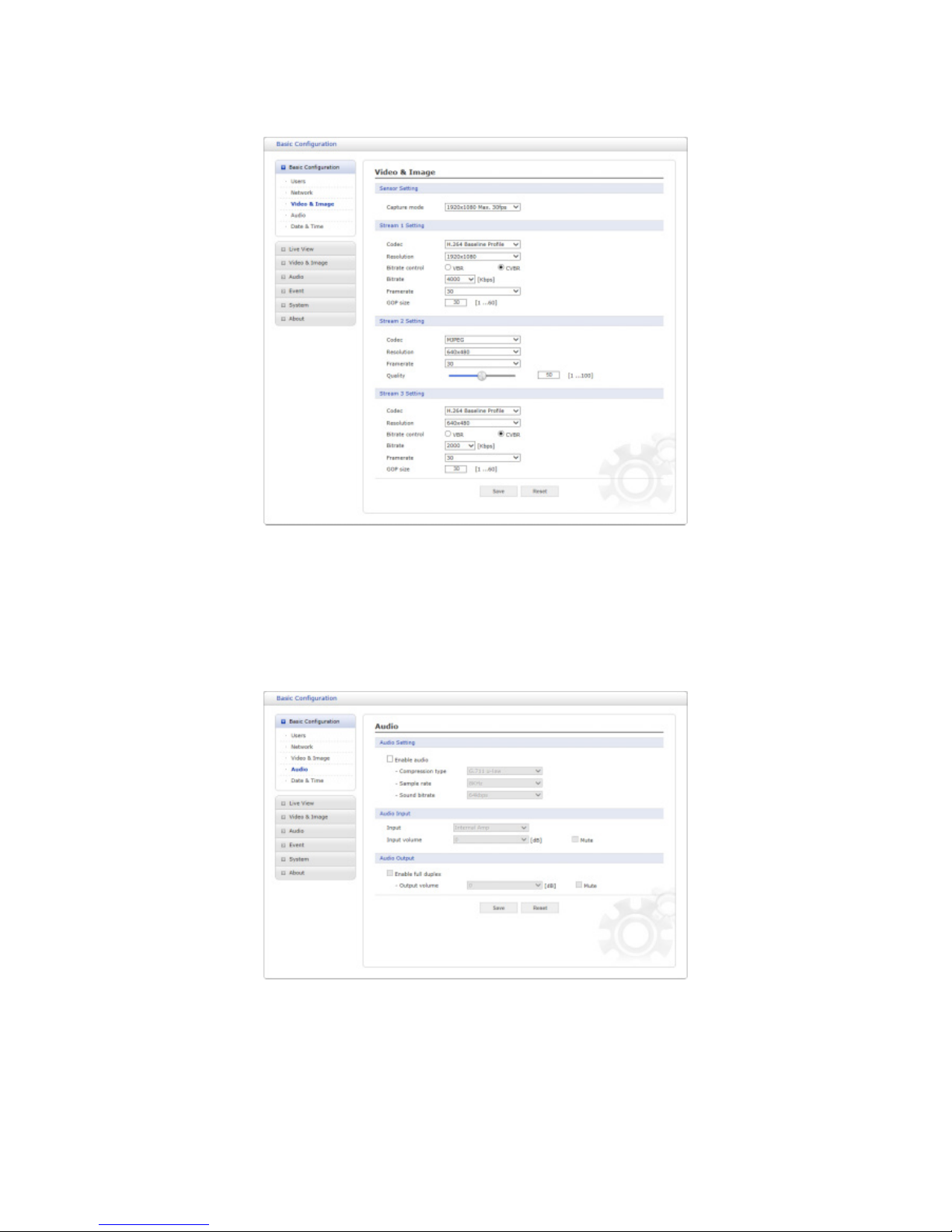
1) Basic
• Sensor Setting:
– Capture mode:
User can select sensor capture mode between 30 fps and 60 fps in full-HD resolution. If 60fps is selected, Stream 3 is disabled and hidden from the window. In
other words, the camera provides triple stream at 30 fps and dual stream at 60
fps.
• Stream 1 Setting:
– Codec: The codec supported in Stream 1 is H.264.
There are 3 pre-programmed stream profiles available for quick set-up. Choose
the form of video encoding you wish to use from the drop-down list:
∗ H.264 HP (High Profile):
Primary profile for broadcast and disc storage applications, particularly for
high-definition television applications (for example, this is the profile adopted
by the Blu-ray Disc storage format and the DVB HDTV broadcast service).
∗ H.264 MP (Main Profile):
Primary profile for low-cost applications that require additional error robustness, this profile is used rarely in videoconferencing and mobile applications;
it does add additional error resilience tools to the Constrained Baseline Profile. The importance of this profile is fading after the Constrained Baseline
Profile has been defined.
∗ H.264 BP (Baseline Profile):
Originally intended as the mainstream consumer profile for broadcast and
storage applications, the importance of this profile faded when the High Profile
was developed for those applications.
24

– Resolution:
This enables users to determine a basic screen size when having an access
through the Web Browser or PC program. The screen size control comes in seven
modes like 1920x1080, 1280x1024, 1280x960, 1280x720, 1024x768, 704x576,
704x480, 640x480, 640x360 and 320x240. Users can change the selected screen
size anytime while monitoring the screen on a real-time basis.
– Bitrate control:
The bit rate can be set as Variable Bit Rate (VBR) or Constrained Variable Bit
Rate (CVBR). VBR adjusts the bit rate according to the image complexity, using
up bandwidth for increased activity in the image, and less for lower activity in
the monitored area. Limiting the maximum bit rate helps control the bandwidth
used by the H.264 video stream. Leaving the Maximum bit rate as unlimited
maintains consistently good image quality but increases bandwidth usage when
there is more activity in the image. Limiting the bit rate to a defined value prevents
excessive bandwidth usage, but images are degraded when the limit is exceeded.
∗ VBR: unlimited maximum bitrate.
∗ CVBR: VBR with maximum bitrate which is set in Bitrate .
– Bitrate: Maximum bitrate for CVBR in the range of 100kbps ∼ 8Mbps.
This is disabled if Bitrate control is set to VBR.
– Frame rate:
Upon the real-time play, users should select a frame refresh rate per second. If
the rate is high, the image will become smooth. On the other hand, if the rate is
low, the image will not be natural but it can reduce a network load.
– GOP size:
Select the GOP (Group of Picture) size. If users want to have a high quality of
fast image one by one, please decrease the value. For the purpose of general
monitoring, please do not change a basic value. Such act may cause a problem
to the system performance. For the details of GOP setting, please contact the
service center.
• Stream 2 Setting:
Sometimes the image size is large due to low light or complex scenery. Adjusting the
frame rate and quality helps to control the bandwidth and storage used by the Motion
JPEG video stream in these situations. Limiting the frame rate and quality optimizes
bandwidth and storage usage, but may give poor image quality. To prevent increased
bandwidth and storage usage, the Resolution, Frame rate, and Frame Quality should
be set to an optimal value.
– MJPEG Resolution: Same as the stream 1 settings.
– MJPEG Frame rate: Same as the stream 1 settings.
– MJPEG Quality: Select the picture quality. If users want to have a high quality
of fast image one by one, please decrease the value. For the purpose of general
monitoring, please do not change a basic value. Such act may cause a problem
to the system performance.
• Stream 3 Setting: Same as the Stream 1 Setting.
When the settings are complete, click Save button to save the settings, or click Reset button
to clear all of the information you entered without saving it.
25
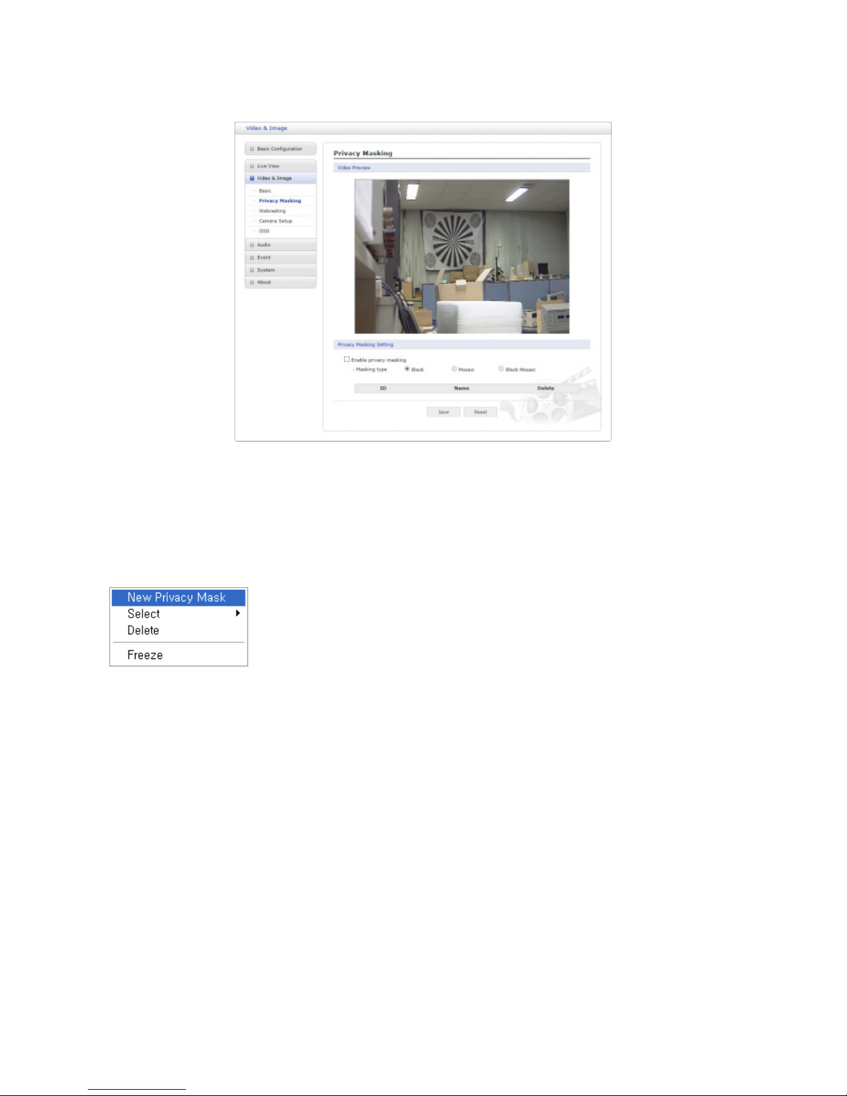
2) Privacy Masking
The privacy masking function allows you to mask parts of the video image to be transmitted.
You can set up to eight privacy masks and the color of privacy masks is black.
The privacy masks are configured by Mask windows. Each window can be selected by clicking with the mouse. It is also possible to resize or delete, or move the window, by selecting
the appropriate window at the mouse menu on the video screen.
To create a mask window, follow steps:
1. Click the right button of mouse to see the mouse menu.
2. Select New Privacy Mask in the mouse menu.
3. Click and drag mouse to designate a mask window area.
When the settings are complete, click Save button to save the settings, or click Reset button
to clear all of the information you entered without saving it.
26
 Loading...