

Vista VK2-1080BXDNe Configuration And User Manual
1
VK2-1080BXDNe
Configuration and user manual

VK2-1080BXDNe manual V1.0
2
3
WARNING
TO REDUCE THE RISK OF FIRE OR ELECTRIC SHOCK, DO NOT EXPOSE THIS PRODUCT TO RAIN OR
MOISTURE. DO NOT INSERT ANY METALLIC OBJECTS THROUGH THE VENTILATION GRILLS OR
OTHER OPENINGS ON THE EQUIPMENT.
CAUTION
EXPLANATION OF GRAPHICAL SYMBOLS
The lightning flash with arrowhead symbol, within an equilateral triangle, is intended to alert
the user to the presence of un-insulated "dangerous voltage" within the product's enclosure
that may be of sufficient magnitude to constitute a risk of electric shock to persons.
The exclamation point within an equilateral triangle is intended to alert the user to the
presence of important operating and maintenance (servicing) instructions in the literature
accompanying the product.
PRECAUTIONS
Safety ---------------------------------- Installation -----------------------------
Cleaning ----------------------------------
CAUTION
RISK OF ELECTRNIC SHOCK
DO NOT OPEN
CAUTION: TO REDUCE THE RISK OF ELECTRIC SHOCK,
DO NOT REMOVE COVER (OR BACK).
NO USER-SERVICEABLE PARTS INSIDE.
REFER SERVICING TO QUALIFIED SERVICE PERSONNEL.
Should any liquid or solid object fall into the cabinet,
unplug the unit and have it checked by the qualified
personnel before operating it any further.
Unplug the unit from the wall oulet if it is not going to
be used for several days or more. To disconnect the
cord, pull it out by the plug. Never pull the cord itself.
Allow adequate air circulation to prevent internal heat
build-up. Do not place the unit on surfaces (rugs,
blankets, etc.) or near materials(curtains, draperies)
that may block the ventilation holes.
Height and vertical linearity controls located at the rear
panel are for special adjustments by qualified
personnel only.
Do not install the unit in an extremely hot or humid place
or in a place subject to excessive dust, mechanical
vibration.
The unit is not designed to be waterproof.
Exposure to rain or water may damage the unit.
Clean the unit with a slightly damp soft cloth.
Use a mild household detergent. Never use strong
solvents such as thinner or benzene as they might
damage the finish of the unit.
Retain the original carton and packing materials for safe
transport of this unit in the future.

VK2-1080BXDNe manual V1.0
4
CE COMPLIANCE STATEMENT
WARNING
This is a Class A product. In a domestic environment this product may cause radio interference in
which case the user may be required to take adequate measures.
CAUTION
RISK OF EXPLOSION IF BATTERY IS REPLACED BY AN INCORRECT TYPE.
DISPOSE OF USED BATTERIES ACCORDING TO THE INSTRUCTIONS

5
IMPORTANT SAFETY INSTRUCTIONS
1. Read these instructions.
2. Keep these instructions.
3. Heed all warnings.
4. Follow all instructions.
5. Do not use this apparatus near water.
6. Clean only with dry cloth.
7. Do not block any ventilation openings. Install in accordance with the
Manufacturer’s instructions.
8. Do not install near any heat sources such as radiators, heat registers, stoves, o
r other apparatus (including amplifiers) that produce heat.
9. Do not defeat the safety purpose of the polarized or grounding-type plug.
A polarized plug has two blades with one wider than the other. Grounding
type plug has two blades and a third grounding prong. The wide blade or the
third prong are provided for your safety. If the provided plug does not fit into
your outlet, consult an electrician for replacement of the obsolete outlet.
10. Protect the power cord from being walked on or pinched particularly at plugs
convenience receptacles, and the point where they exit from the apparatus.
11. Only use attachments/accessories specified by the manufacturer.
12. Use only with the cart, stand, tripod, bracket, or table
specified by the manufacturer, or sold with the apparatus.
When a cart is used, use caution when moving the
cart/apparatus combination to avoid injury from tip-over.
13. Unplug this apparatus during lightning storms or when
unused for long periods of time.
14. Refer all servicing to qualified service personnel. Servicing is
required when the apparatus has been damaged in any way, such as power-
supply cord or plug is damaged, liquid has been moisture, does not operate
normally, or has been dropped.
15. CAUTION – THESE SERVICING INSTRUCTIONS ARE FOR USE BY
QUALIFIED SERVICE PERSONNEL ONLY. TO REDUCE THE RISK
OF ELECTRIC SHOCK DO NOT PERFORM ANY SERVICING OTHER
THAN THAT CONTAINED IN THE OPERATING INSTRUCTIONS
UNLESS YOU QRE QUALIFIED TO DO SO.
16. Use satisfy clause 2.5 of IEC60950-1/UL60950-1 or Certified/Listed Class
2 power source only.
17. ITE is to be connected only to PoE networks without routing to the outside plant.

VK2-1080BXDNe manual V1.0
6

7
Contents
Contents ............................................................ 7
1. DESCRIPTION ........................................... 10
1.1 Key Features ..................................................................................................................... 10
1.2 Camera overview ............................................................................................................... 12
2. INSTALLATION .......................................... 14
2.1 DC Auto Iris Lens Installation & Adjustment ....................................................................... 14
2.2 Audio Connection .............................................................................................................. 18
2.3 Alarm Connection .............................................................................................................. 18
3. IP address set up ...................................... 19
Minimum conditions for using web browser .............................................................................. 19
3.1 SmartManager ................................................................................................................... 20
3.2 Operation ........................................................................................................................... 21
3.2.1 Access from a browser ............................................................................................. 21
3.2.2 Live View Page ........................................................................................................ 22
3.2.3 PLAYBACK .............................................................................................................. 24
4. SETUP ........................................................ 27
4.1 Basic Configuration ............................................................................................................ 27
4.1.1 Basic - Users ........................................................................................................... 28
4.1.2 Basic - Network ........................................................................................................ 31
4.1.3 Basic - Video & Image ............................................................................................. 32
4.1.4 Basic - Audio............................................................................................................ 35

VK2-1080BXDNe manual V1.0
8
4.1.5 Basic - Date & Time ................................................................................................. 37
4.2 Video and image ................................................................................................................ 38
4.2.1 Video & Image - Basic .................................................................................................... 38
4.2.2 Video & Image - Appearance ................................................................................... 40
4.2.3 Video & Image - AE & AWB ..................................................................................... 41
4.2.4 Video & Image - Day & Night ................................................................................... 43
4.2.5 Video & Image - Privacy Mask ................................................................................. 44
4.2.6 Video & Image - Webcasting .................................................................................... 45
4.3 Audio ................................................................................................................................. 46
4.3.1 Audio - Basic............................................................................................................ 46
4.4 Event ................................................................................................................................. 48
4.4.1 Event – Event in ....................................................................................................... 48
4.4.2 Event - Event Out .................................................................................................... 53
4.5.6 Event - Event Out – PTZ Preset ............................................................................... 62
4.5.7 Event - Event Out – Record ..................................................................................... 63
4.4.3 Event - Event Map ................................................................................................... 65
4.5 Device................................................................................................................................ 67
4.5.1 Device - PTZ ............................................................................................................ 67
4.5.2 Device - RS485 ........................................................................................................ 68
4.6 System............................................................................................................................... 69
4.6.1 System - Information ................................................................................................ 69
4.6.2 System - Date & Time .............................................................................................. 76
4.6.3 System - Network .................................................................................................... 78
4.6.3.3 System - Network - RTP ....................................................................................... 81
4.6.4 System - Language .................................................................................................. 89
4.6.5 System - Maintenance ................................ ............................................................. 90

9
4.6.6 System - Support ..................................................................................................... 92
4.7 About ................................................................................................................................. 93
5. Troubleshooting ........................................... 94
6. Upgrading Firmware ................................. 95

VK2-1080BXDNe manual V1.0
10
1. DESCRIPTION
The VK2-1080BXDNe camera is an internet protocol based megapixel network camera with a builtin web based viewer on Internet Explorer®. The camera has a connection feature for third-party
applications and compatible with supplied Utility software for easy installation and Client software to
search, configure, manage, live view, record and playback.
The camera supports triple streaming. The standard compression formats including H.264,MPEG4
and MJPEG. The three streams can be configured to a variety of resolutions, bit rates and frame
rates.
The camera uses 1/2.8 inch CMOS sensor and complies with CS mount lens and also supports PoE
(Power over Ethernet), DC12V, and AC24V.
1.1 Key Features
- HDTV Video Quality
The VK2-1080BXDNe is capable of providing the outstanding image quality with HDTV performance
and profiles (High, Main, and Baseline) in H.264 compression.
- Triple streaming
The Network Camera can deliver dual or triple video streams simultaneously at full frame rate in all
resolutions up to Full-HD(1920 x 1080p) using Motion JPEG and H.264 (or MPEG-4). This means
that several video streams can be configured with different compression formats, resolutions and
frame rates for different needs.
- Day and Night
The VK2-1080BXDNe provides clear monitoring images even in low light conditions using IR-cut
filter.
- Easy Focus
Easy Focus helps to reduce the installation efforts especially video image focusing of the camera.
- Digital PTZ
Supports maximum 10x digital zoom.
- Intelligent Video Motion Detection
The VK2-1080BXDeN offers intelligent & sophisticated video motion detection for each multiple
streams.
- Triple Power (Power over Ethernet, DC12V, AC24V)
This camera supports Power over Ethernet (PoE), which supplies power to the camera through the
network. If the network has not PoE, connect a DC12V or AC24V power connector.

11
- SD Local Recording
The VK2-1080BXDNe provides local video recording function. When camera detects video motion
or alarm events or manual trigger, it can record video stream by itself.
- Voice Alert Linked to Alarm Detection
The VK2-1080BXDNe can play the audio file stored in the camera in synchronization with alarm
detection by the sensor input or the motion detection function.
- Network Flow Control
The VK2-1080BXDNe provides a flow control function which enhances network efficiency by
significantly restricting user video streams with designating the maximum bandwidth.
- ONVIF Certificate
The VK2-1080BXDNe network camera complies with the ONVIF certificate. ONVIF (Open Network
Video Interface Forum) is an open industry forum for the development of a global standard for the
interface of network video products.
Components
Quantity Description
1 Camera
1 Installation CD
1 C- Mount Ring
1 Auto DC-Iris Connector
NOTE
Lens, installation hardware and Adapter for DC12V / AC24V are not supplied.
VK2-1080BXDNe manual V1.0
12
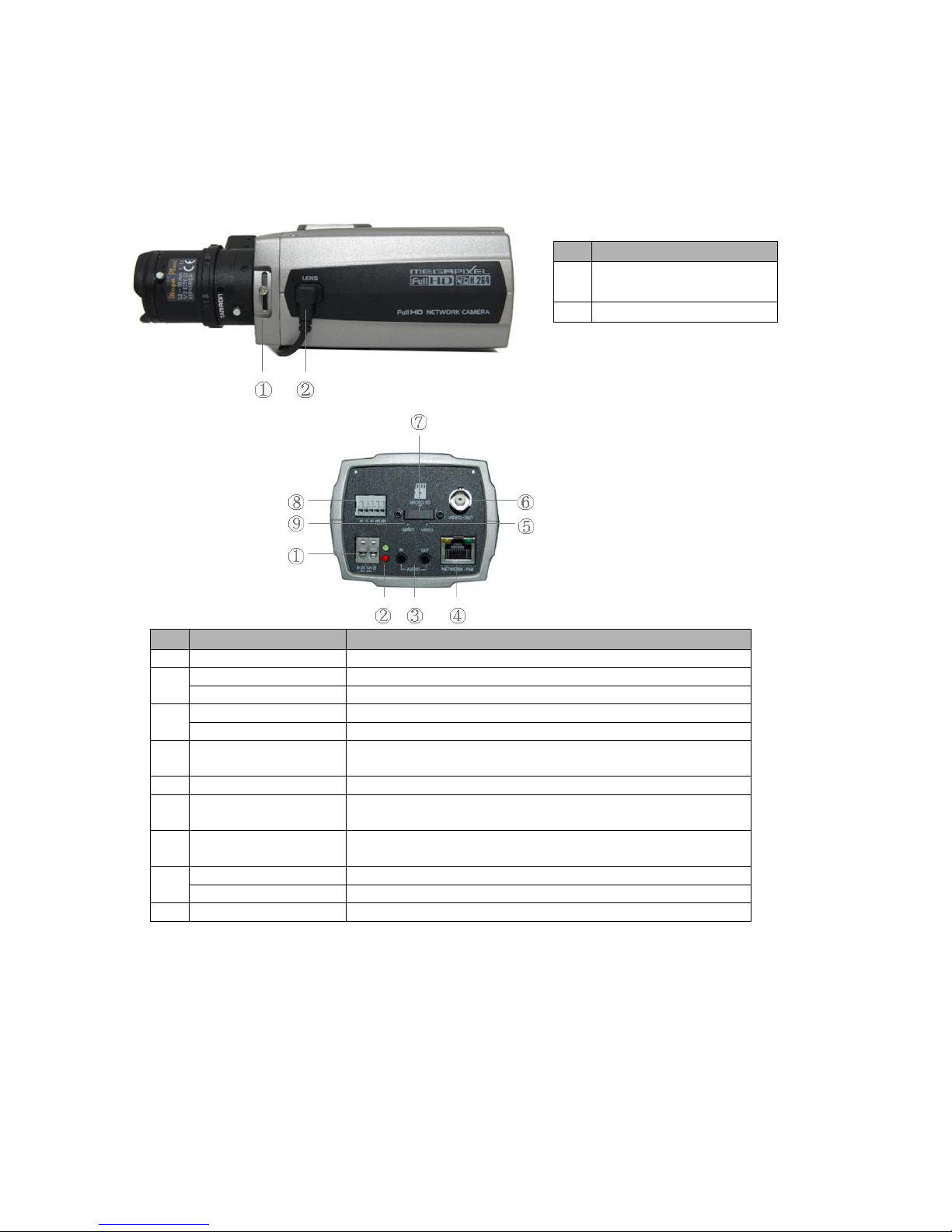
1.2 Camera overview
• Front View
NO
Function
1
Back-focus adjusting locking
screw
2
Auto IRIS lens connector
• Rear View
NO
Function
Description
1
Power Adaptor Terminal
Main Power, 2pin terminal, DC12V/AC24V 330mA(4.0W)
2
Power Indicator(Green)
Indicates power input.
Status Indicator(Red)
Indicates camera status.
3
Audio Input
Audio Input Stereo Jack
Audio Output
Audio Output Stereo Jack
4
Network Connector
(PoE)
RJ-45 port compatible with 10/100Mbps having PoE functionality.
5
Video Switch
Selects Video On/Off. Set to On to output a video signal.
6
Video Output
Connects the video output. This BNC connector provides a
1.0Vp-p/75 ohms composite video signal.
7
Micro SD Card Slot
Card Slot for Micro SD. Open the protection cover with a
supported tool to insert Micro SD card.
8
3pin Terminal IO
Connects alarm In/Out.
2pin RS485 Terminal
Connects PT device.
9
Reset Button
Executes the factory default.
Note: Video Output is used for an easy zoom and focus control when installing lens. After lens
installation, you must set Video Switch to Off to provide the best performance of the Network
Camera.

13
• LED Indicators
LED
Color
Indication
Network
Green
Steady for connection to a 100 Mbit/s network. Flashes for
network activity.
Amber
Steady for connection to 10 Mbit/s network. Flashes for
network activity.
Unlit
No network connection.
Status
Red
Steady red for failed upgrade or booting.
Power
Green
Steady green for normal operation or booting.
Flashes green during firmware upgrade.
Note: Steady green and red during booting. Flash green and red during factory default.

VK2-1080BXDNe manual V1.0
14
2. INSTALLATION
NOTES
- Use megapixel lens for higher image quality.
- Megapixel lenses are designed and tested to deliver optimal image quality to the VK2-1080BXDNe
megapixel cameras.
- If the standard definition lens was installed on megapixel camera, the image quality will be poor
than expected.
- Recommend Lenses - VDD31V812IRP-3MP (Direct drive iris)
VM31V812IRP-3MP (Manual iris)
Starting Installation
1. Install the Lens
- Ensure the lens does not touch camera CCD sensor.
- If DC auto iris lens is required, connect DC auto iris 4-pin connector into iris drive connector
located on the side of the camera.
2. Mount the camera
The camera can be mounted from both top and bottom.
3. Connect other peripheral devices
Connect the other peripheral devices such as Alarm, Audio and BNC connector.
4. Supply the camera with power.
- If PoE is not available, connect DC12V or AC24V wires to the camera power connector. Ensure
correct polarity when using DC12V. Use a Class2 power.
- This camera complies with IEEE802.3af standard. Hence the power for the camera can be
supplied via Ethernet cabling without additional power supply.
- The camera will complete a configuration process within approximately 40 seconds. The amber
LED flashes once per second after the configuration process is complete.
5. View the camera image
View the camera image using the BNC connector or built-in web browser or supplied Client software.
NOTE
This camera will autosense and work with either a straight Ethernet cable or crossover Ethernet
cable.
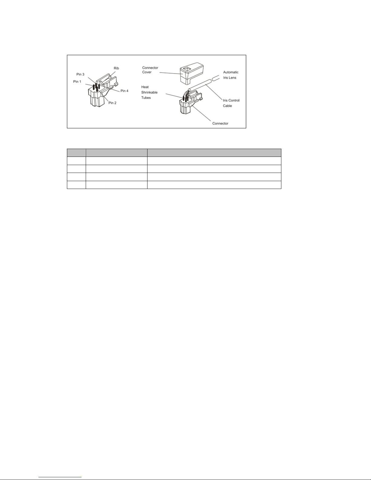
2.1 DC Auto Iris Lens Installation & Adjustment
Camera Adjustment
1) Video auto IRIS installation & adjustment
The camera supports video-type auto iris lenses which adjust to changing light levels.
Perform the following steps to install and adjust a video-type auto iris lens.
If necessary, solder the lens control wires to the connector supplied with the camera.
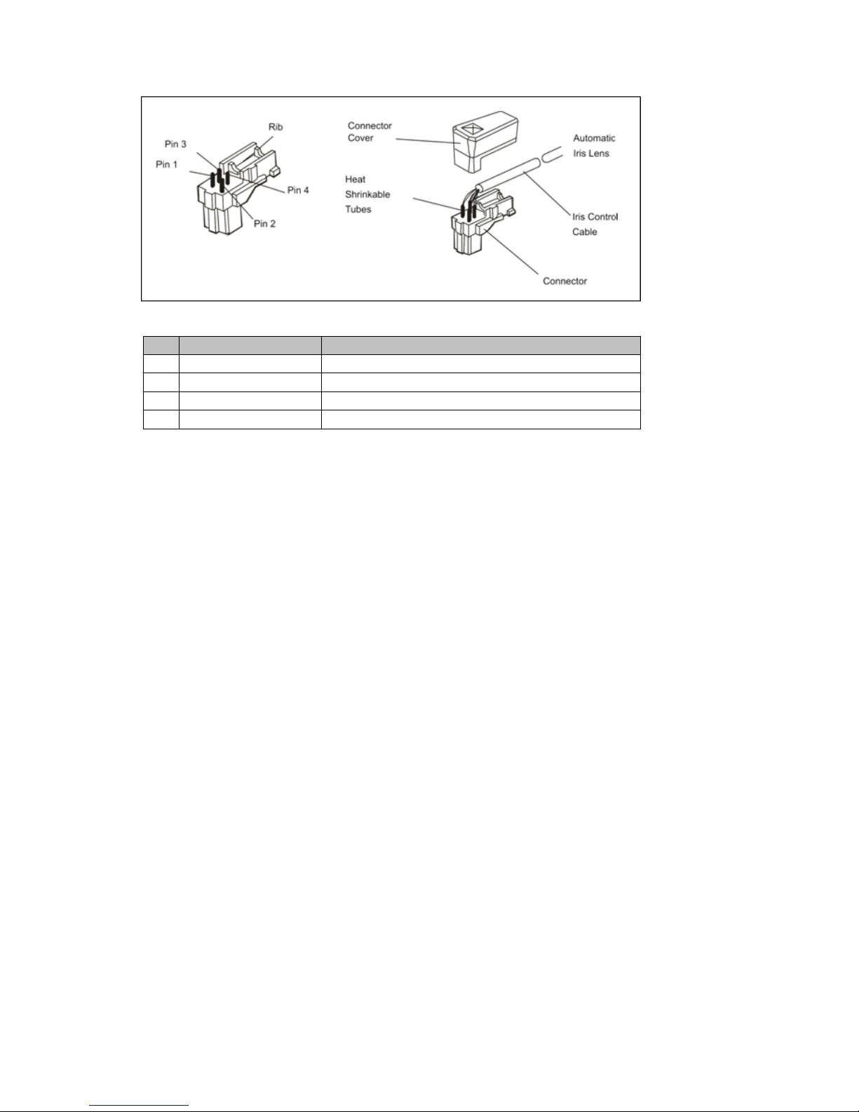
15
1. Attach the video-type auto iris lens to the lens mount on the front of the camera.
Pin
Name
Wire Color
1
Voltage +
Red
2
Open
-
3
Video
White
4
Ground
Black
2. IMPORTANT: The minimum Plug the connector from the lens into the auto iris jack on the back of the
camera. The connector is polarized and can only be inserted into the jack one way.
3. Apply power to the camera.
4. The OSD AE menu in the lens select should be in the “VIDEO”.
5. Adjust the focus ring on the lens for an optimum picture. If a picture is not visible, set the lens for
proper exposure by adjusting the ALC (Automatic Level Control) and the level on the lens. The ALC
setting can range between AVG (average) or PK (peak). A midrange setting is appropriate for most
applications.
For ALC adjustments: AVG To slow the reaction of the lens to changing light, set the range to the
AVG setting to average the video level from the camera. Use when there are bright spots in the
picture such as lights or glare from the sun.
PK To increase the speed of the lens reaction to the changing light, set the lens adjustment to PK so
the lens will adjust to the brightest or peak object in the video. Use this setting if you want to see
the brightest object and not the background objects.
For Level adjustments: Adjust the level control for the best picture during the day. A night
adjustment may not provide the proper setting for controlling the light during the day.
6. Set the back focus of the camera before the final adjustment of the video level.
7. If the auto iris has a gain adjustment and the picture oscillates between open and closed under
bright lights, slowly turn the gain adjustment counter clockwise until the oscillating stops. Increase
the light getting to the camera by adjusting the level control and re-adjusting the gain control.
VK2-1080BXDNe manual V1.0
16
2) DC auto IRIS lens installation & adjustment
1. Solder the lens control wires to the connector supplied with the camera.
Pin
Name
Wire Colour
1
Damp Coil -
Blue
2
Damp Coil +
Red
3
Drive Coil +
White
4
Drive Coil -
Green
2. Attach the DC-type auto iris lens to the lens mount on the front of the camera.
3. Plug the connector into the auto iris jack on the side of the camera. The connector is polarized and
can only inserted into the jack one way.
4. Apply power to the camera.
3) Manual IRIS lens adjustment
When using a manual iris lens, turn the iris ring on the lens to the OPEN position and adjust the manual
iris for the appropriate range. Adjust during the brightest conditions, opening the lens to the minimum fstop yielding a good picture under the brightest scene conditions. Do not saturate the picture.
The manual iris is used in indoor applications where lighting from windows can considerably affect the
light level of the room.
4) Back Focus adjustment
For best results, perform back focus adjustments at night or while using a #6 or #8 welder's glass in front
of the lens. The focus of the camera will change slightly if the camera iris was adjusted on a light scene,
then changes to a dark scene. However, the camera will remain in focus if the iris was focused on a
dark scene and the scene lightens.
1. The lens should be mounted on the camera before applying power.
2. If a picture is visible, focus on the picture. If the picture is not visible, open the iris on the lens.
Open the lens as wide as possible by placing the welder's glass in front of the lens and forcing the
lens to automatically open.
3. When the iris is open to the widest point, re-adjust the focus for clear picture. If a clear picture is
not possible, set the focus ring to midrange.
4. Loosen the back focus lock screw.
5. Adjust the back focus ring for a clear picture.
6. Tighten the back focus lock screw.
7. Fine tune the focus with the focus ring on the lens.
8. Remove the welder's glass from in front of the lens.
9. Adjust the iris of the lens for the best picture quality.

17
5) Zoom lens back focus adjustment
The objective of back focusing a zoom lens is similar to that of a fixed focal length camera except the
back focus is also adjusted to maintain the focus when "zooming" the lens in and out on a scene.
1. Choose an object at the farthest range set for viewing with a zoom lens.
2. Make sure the iris of the lens is wide open. Do this by adjusting the camera at night or use a
welders glass in front of the lens.
3. Adjust the focus to the stop on the far range.
4. Adjust the zoom on the lens to obtain the widest picture.
5. Loosen the back focus lock screw.
6. Adjust the back focus ring for the clearest picture.
7. Tighten the back focus lock screw.
8. Adjust the zoom on the lens to the far telephoto position.
9. Adjust the back focus ring for the clearest picture.
10. Adjust the zoom on the lens back to the widest picture.
11. Loosen the back focus screw.
12. Re-adjust the back focus for the clearest picture.
13. Tighten the back focus lock screw.
14. Repeat the previous steps as necessary to maintain a clear picture throughout the entire zoom
range.
VK2-1080BXDNe manual V1.0
18
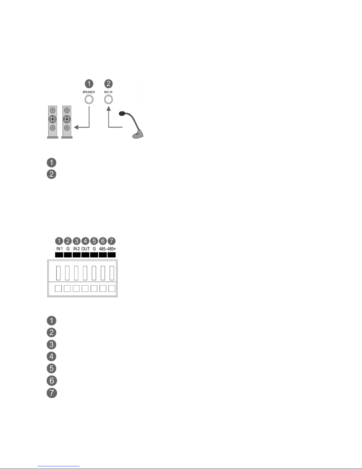
2.2 Audio Connection
This camera supports bidirectional audio. Install the microphone and a speaker with ampllifier
capability.
Figure 3. Audio connection
External Speaker
External Microphone
2.3 Alarm Connection
The camera provides two alarm input for external signalling devices and one alarm output for
activating external devices. Both Normally Open and Normally Closed devices are supported.
Figure 4. Alarm connector
Alarm Input 1
Alarm Ground
Alarm Input 2
Alarm Output
Alarm Ground
RS485 RS485 +

19
3. IP address set up
Before powering up the camera, installation must be complete. The camera completes a
configuration sequence taking approximately 40 seconds from powering up. Once completed the
amber LED will flash once a second.
NOTES
- If the DHCP is enabled but the camera is not connected to a DHCP server, the camera will be set
default IP 192.168.30.220 and try to get IP from DHCP server about every two seconds.
- Network and processor bandwidth limitations might cause the video stream to pause or appear
pixelated when an increased number of Web-interface users connect to the camera. Decrease the
images per second, resolution, compression, or bit rate settings of the Web-interface video
streams to compensate for network or processor limitations.
Minimum conditions for using web browser
The minimum system requirements to use a Web browser with this IP camera are as follows:
- CPU: Pentium® 4 microprocessor, 2.0GHz
- Operational System: Windows XP® or Windows Vista® or Windows7®
- System Memory: RAM 512 Mbyte
- Ethernet: 100 Mbit
- Video Resolution: 1024(Horizontal) x 768(Vertical) pixels or higher
- Internet Explorer® 7 or later
- ActiveX® 1.0.0.13 or later
VK2-1080BXDNe manual V1.0
20
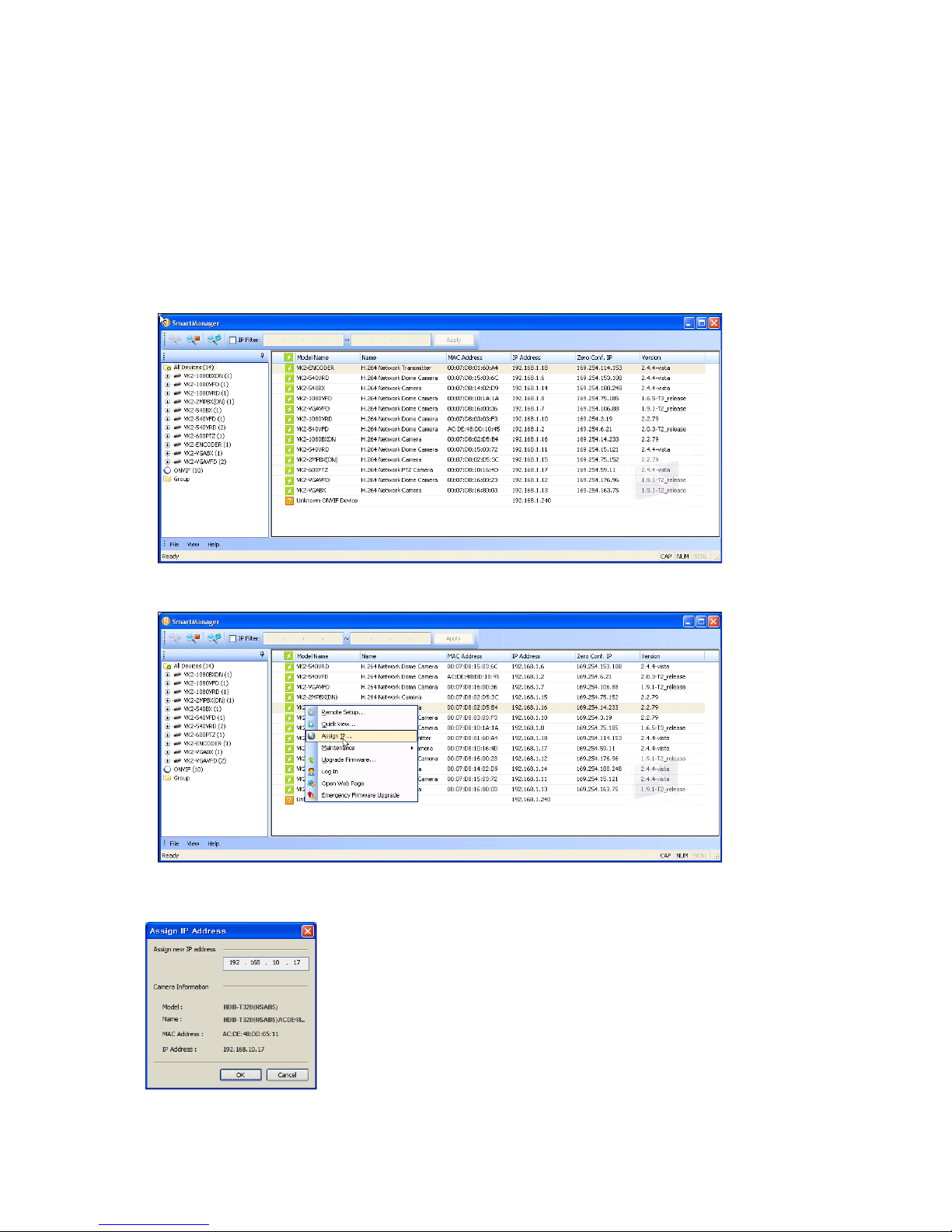
3.1 SmartManager
When the camera is first connected to the network it is necessary to allocate an IP address to the device with
the “Smart Manager” utility on the CD.
1. Connect the camera to the network and power up.
2. Start SmartManager utility is available on the supplied CD. Load this onto the PC and run the program.
The main window will be displayed, after a short while any network devices connected to the network will
be displayed in the list.
3. Select the camera on the list and click right button of the mouse. You will see the pop-up menu as below.
4. Select Assign IP. You will see an assign IP window. Enter the required IP address.
Note: For more information, refer to the Smart Manger User’s Manual.
21
3.2 Operation
The Network Camera can be used with Windows operating system and browsers. The recommended
browsers are Internet Explorer, Safari, Firefox, Opera and Google Chrome with Windows.
NOTE: To view streaming video in Microsoft Internet Explorer, set your browser to allow ActiveX controls.
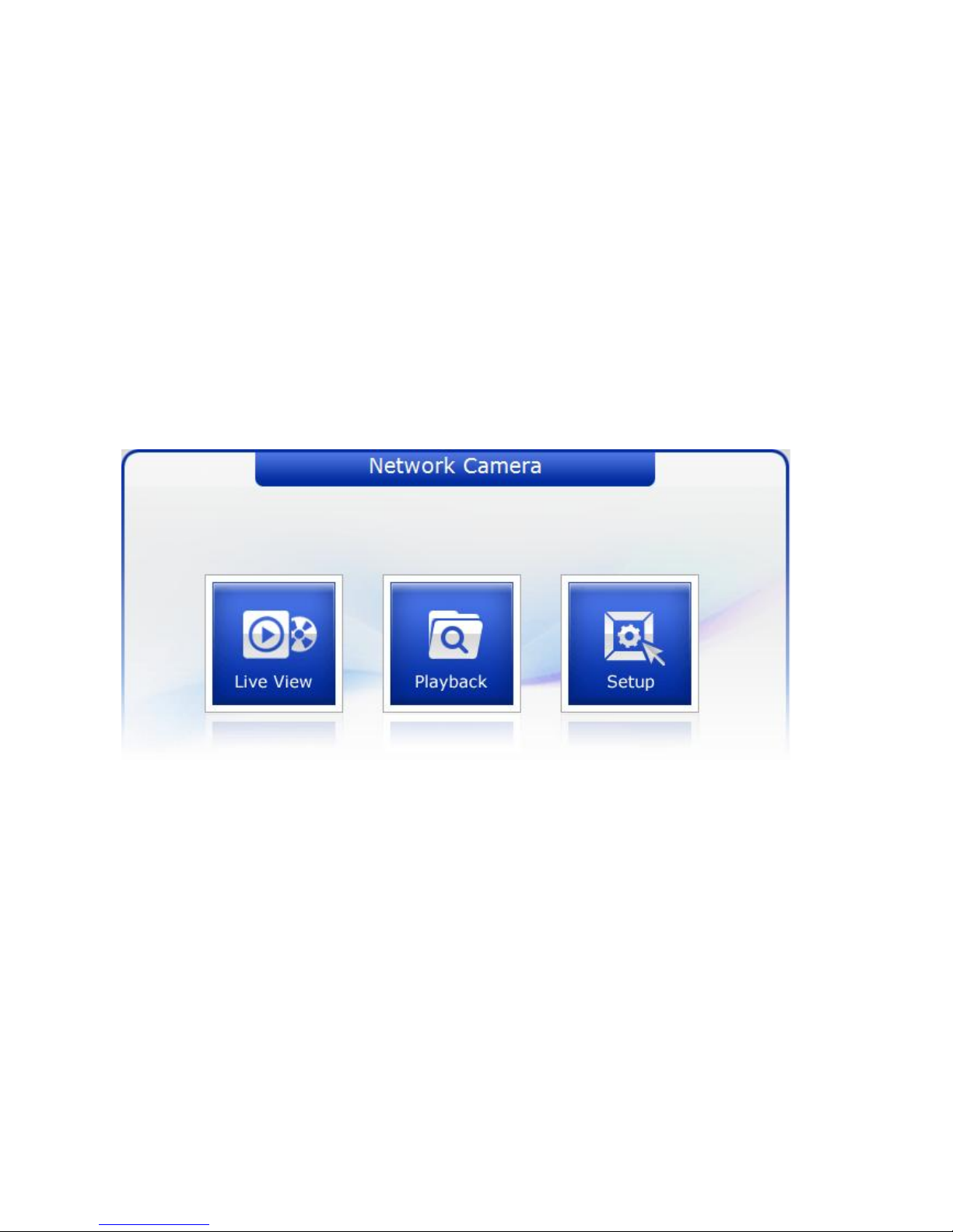
3.2.1 Access from a browser
1. Start a browser (Internet Explorer).
2. Enter the IP address or host name of the Network Camera in the Location/Address field of your browser.
3. Default User = admin, default password = admin
4. You will see the following page. Click Live View or Setup to enter web page.
NOTE
For security purposes, be sure to change the password after you log on for the first time.
VK2-1080BXDNe manual V1.0
22
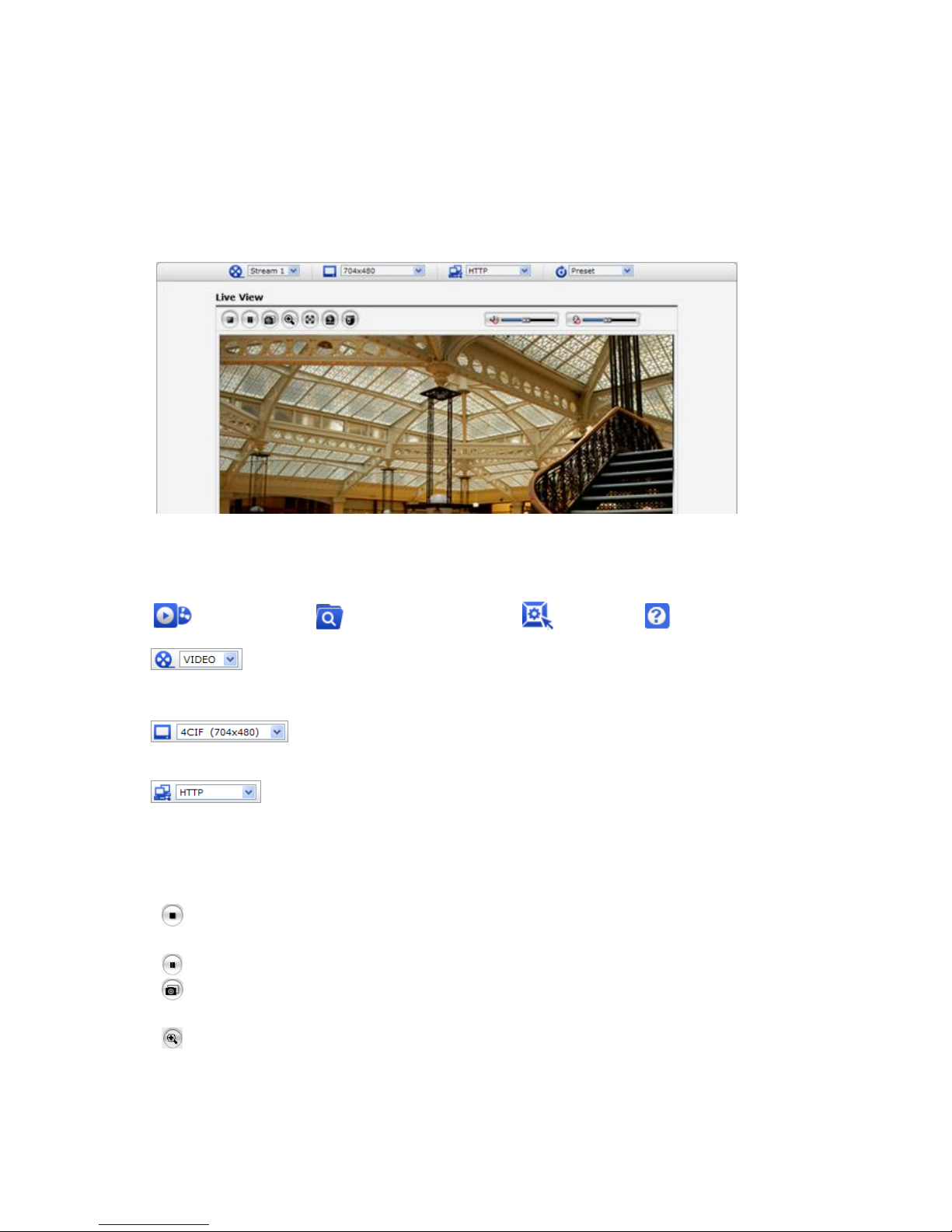
3.2.2 Live View Page
The live view page comes in eight screen modes: 1920x1080, 1280x1024, 1280x720, 720x480(576), 640x480,
352x240(288), and 320x240. Users are allowed to select the most suitable one out of those modes. Please,
adjust the mode in accordance with your PC specifications and monitoring purposes.
1) General controls
Live View Page Search & Playback Page Setup Page Help Page
The video drop-down list allows you to select a customized or pre-programmed video
stream on the live view page. Stream profiles are configured under Setup > Basic Configuration > Video
& Image. For more information, please see “3.5.1 Basic Configuration > Video & Image” of User’s Manual.
The resolution drop-down list allows you to select the most suitable one out of
video resolutions to be displayed on live view page.
The protocol drop-down list allows you to select which combination of protocols and
methods to use depends on your viewing requirements, and on the properties of your network.
2) Control toolbar
The live viewer toolbar is available in the web browser page only. It displays the following buttons:
The Stop button stops the video stream being played. Pressing the key again toggles the
start and stop. The Start button connects to the network camera or start playing a video stream.
The Pause button pause the video stream being played.
The Snapshot button takes a snapshot of the current image. The location where the
image is saved can be specified.
The digital zoom activates a zoom-in or zoom-out function for video image on the live
screen.

23
The Full Screen button causes the video image to fill the entire screen area. No other
windows will be visible. Press the 'Esc' button on the computer keyboard to cancel full
screen view.
The Manual Trigger button activates a pop-up window to manually start or stop the event.
The PTZ button activates a pop-up window for Pan, Tilt and Zoom control.
Use this scale to control the volume of the speakers.
Use this scale to control the volume of the microphone.
Use this scale to control the volume of the speakers and microphones.
3) Video and Audio Streams
The network camera provides several images and video stream formats. Your requirements and the
properties of your network will determine the type you use.
The Live View page in network camera provides access to H.264, MPEG-4 and Motion JPEG video
streams, and to the list of available video streams. Other applications and clients can also access these
video streams/images directly, without going via the Live View page.
VK2-1080BXDNe manual V1.0
24
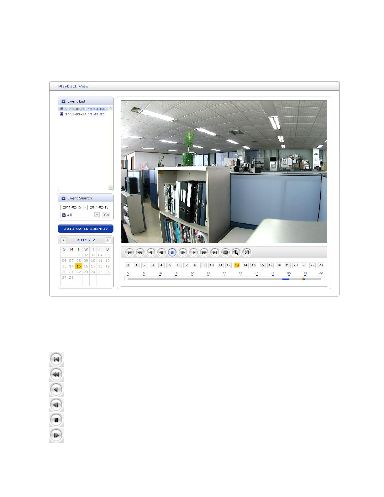
3.2.3 PLAYBACK
Users can access the recorded images from the SD card via the web browser.
Event List: Shows the recorded list of events.
Event Search: Select the start date and end date you want to playback, and then click the Go button to show
the list. The list can be tailored to show only one type or all events.
Calendar: Use the calendar to select a specific day
Playback Control Buttons: details below of individual icons
Go to the first.
Fast backward play
Backward play
Backward step
Pause
Forward step
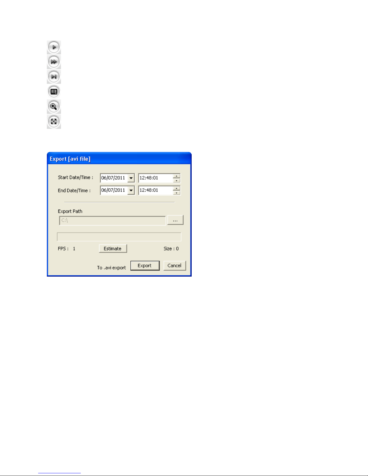
25
Forward play
Fast forward play
Go to the last
Clip copy
Digital Zoom
Full Image
Clip Copy: Downloads an avi format file.
1. Select Start Date/Time and End Date/Time.
2. Set Export Path.
3. Click Estimate button which is shown the file FPS and Size.
4. Click Export or Cancel button.
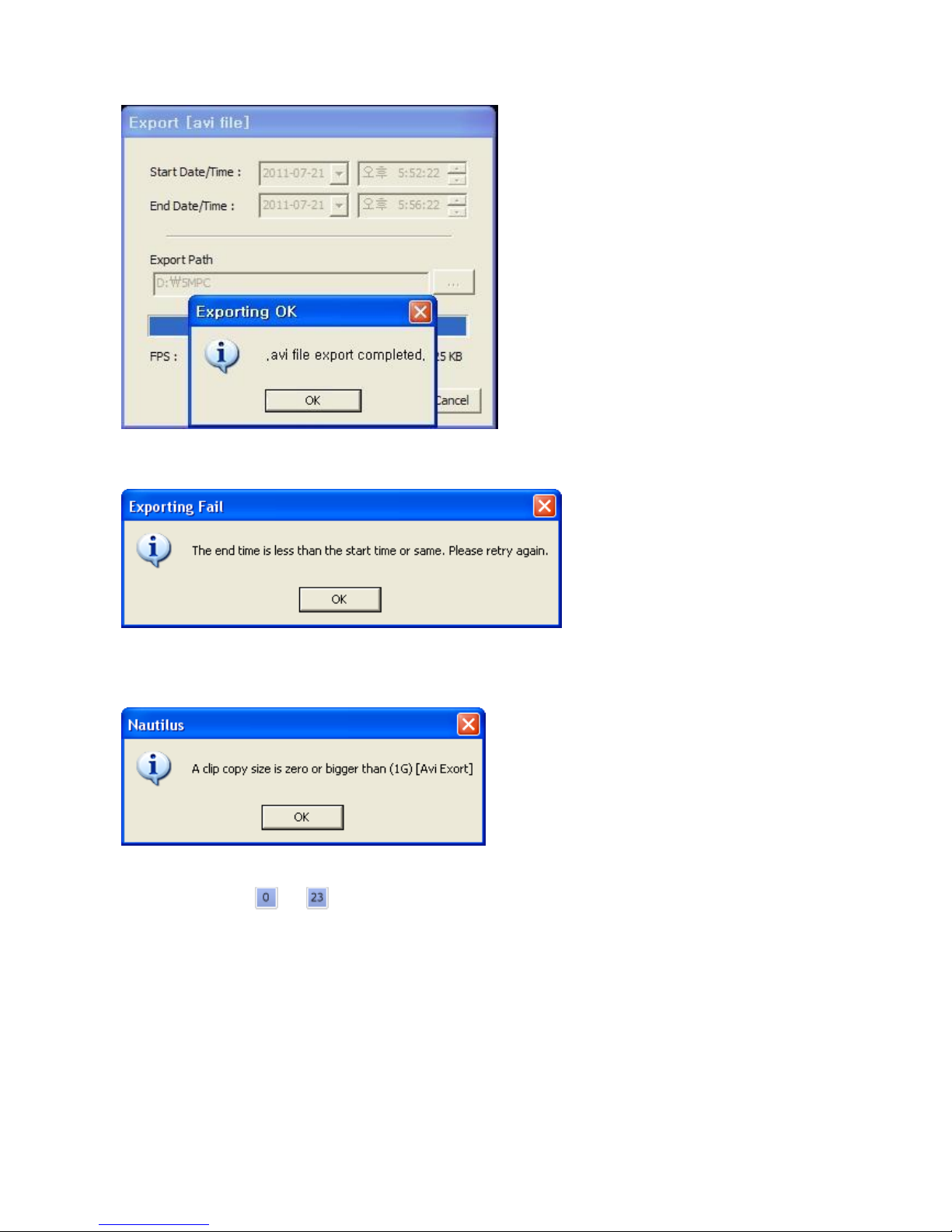
NOTES
1. If you set successfully, the following pop-up windows will be appeared.
VK2-1080BXDNe manual V1.0
26
2. In case of mismatching of the Start or End Date/Time, the following windows will be appeared.
Please retry to set the Start or End Date/Time.
3. In case of no image data between the Start Date/Time and End Date/Time, the following windows will be
appeared.
Please retry to set the Start or End Date/Time.
4. The buttons from to indicate an Hours and the number from 0 to 60 indicate a minutes.
27
4. SETUP
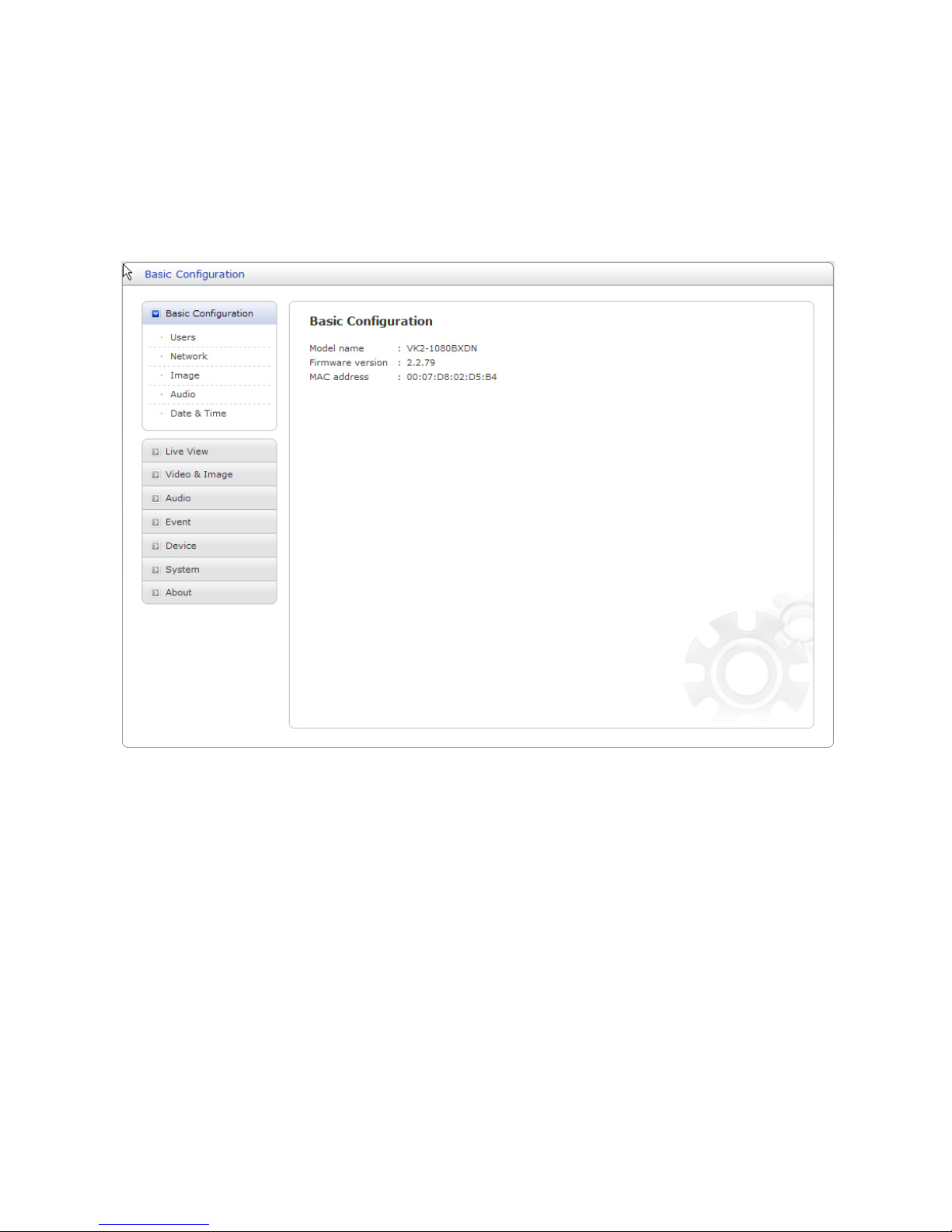
4.1 Basic Configuration
Use this section to set up the basic settings of the camera. It will allow the user to gain access to the
live image and audio.
NOTE
The setting menu might not be available if the user does not have the permission to access this
feature. To gain access to the image the only setting that is required to be set is the IP address,
found in the Network section.
VK2-1080BXDNe manual V1.0
28
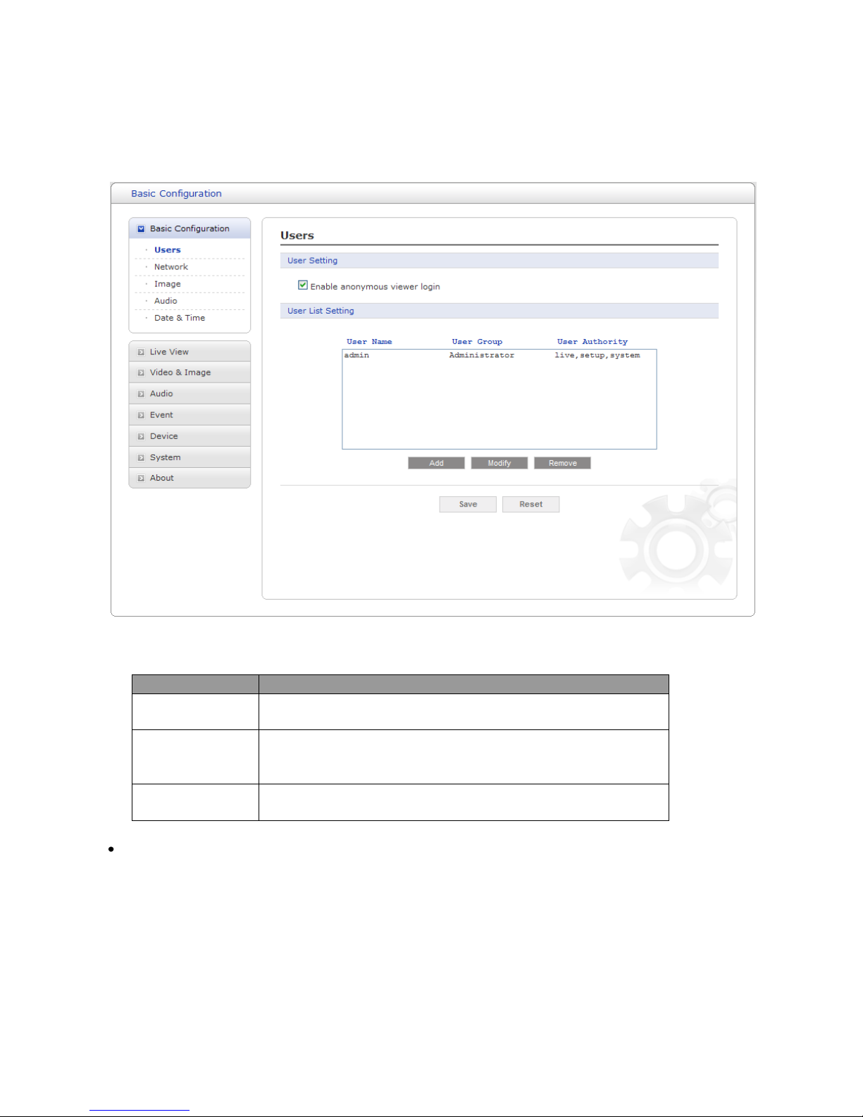
4.1.1 Basic - Users
Use the Users tab to manage user permissions for accessing the camera.
The user list displays the authorized users and user groups (levels):
User Group
Authority
Guest
Provides the lowest level of access, which only allows access to
the Live View page.
Operator
An operator can view the Live View page, create and modify
events, and adjust certain other settings. Operators have no
access to System Options.
Administrator
An administrator has unrestricted access to the Setup tools and
can determine the registration of all other users.
Enable anonymous viewer login: Check the box to use the webcasting features. Refer to “3.5.2 Video
& Image” for more details.
29
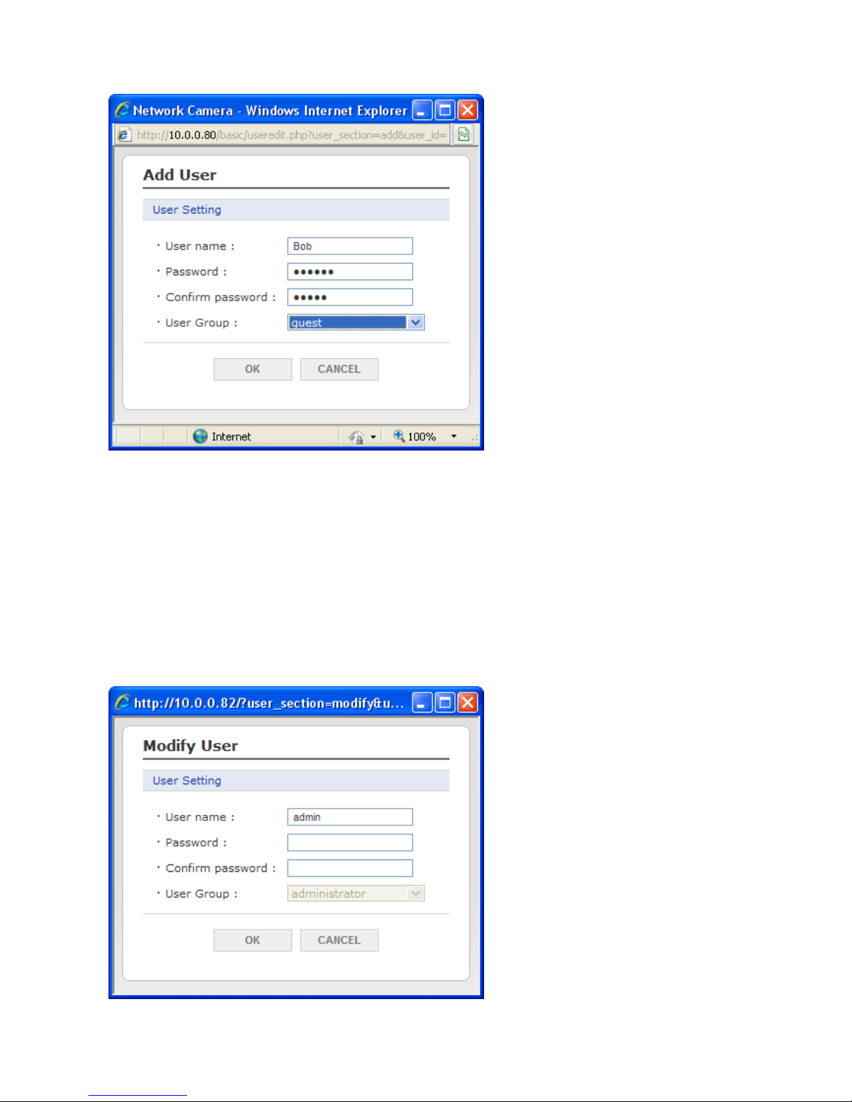
To add a new user:
1. Click the Add button, new pop-up window above will appear.
2. Click in the User name box and type a new user name (1 to 14 alphanumeric characters). User
names are not case sensitive.
3. Click in the Password box and type a password (1 to 8 alphanumeric characters). Passwords are
case sensitive.
4. Click in the Confirm password box and retype a password.
5. Click in the User group box and select one of the groups you wish to assign to the user.
6. Click the OK button to save the settings and add a new user.
 Loading...