

PowerDome Series
Installation Manual

Electromagnetic Compatibility (EMC)
This is a Class A product, in a domestic environment it may cause radio interference, if this is the case
the user may be required to take remedial measures.
Manufacturer’s Declaration of Conformance
A Declaration of Conformity in accordance with the following EU standards has been made and is kept on
file at Norbain SD Ltd. Norbain House, Eskdale Road Wokingham, RG41 5TS.
The manufacturer declares that the product supplied with this document is compliant the provisions of the
EMC Directive 89/336 EEC, the Low Voltage Directive LVD 73/23, the CE Marking Directive 93/68 EEC,
and all associated amendments.
This document is intended to provide accurate information, however, the information contained herein is
subject to change without notice Vista, in keeping pace with technological advances, ia a company of
product innovation. Therefore, it is difficult to ensure that all information provided is entirely accurate and
up-to-date. Vista accepts no responsibility for any inaccuracies or omissions and specifically disclaims
any liabilities, loss, or risk, personal or otherwise which is incurred as a consequence, directly or
indirectly, of the use and/or application of any of the contents of this document.
Specifications subject to change without notice.
2 1040647A / July 2003

PowerDome Installation Manual Table of Contents
TABLE OF CONTENTS
BEFORE YOU BEGIN .......................................................................................................... 5
1 INTRODUCTION ............................................................................................................ 6
1.1 D
1.2 O
1.3 C
1.4 P
1.5 P
ESCRIPTION...................................................................................................... 6
PERATION REQUIREMENTS ................................................................................ 6
ABLE REQUIREMENTS........................................................................................ 6
OWER REQUIREMENTS ...................................................................................... 7
OWER CABLE SIZE AND LENGTH......................................................................... 7
2 HOUSING INSTALLATION............................................................................................... 8
2.1 6 INCH FLUSH-MOUNT HOUSING INSTALLATION USING THE VPD-T600 ................... 9
2.1.1 Installing the Housing ....................................................................................................10
2.2 7 INCH PENDANT-MOUNT HOUSING INSTALLATION ............................................... 14
2.2.1 Using the VPD-WM Wall Mount ....................................................................................14
2.2.1.1 Creating a Conduit Hole................................................................................. 19
2.2.2 Using the VPD-EWM Wall-Mount Bracket ....................................................................20
2.2.2.1 Creating a Conduit Hole................................................................................. 23
2.2.3 Using the VPD-ESM Swing-Arm Mount ........................................................................ 24
3 PTZ AND DOME INSTALLATION................................................................................... 29
3.1 RS485 TERMINATION........................................................................................ 29
3.2 I
3.3 S
3.4 I
NSTALLING THE PAN/TILT ASSEMBLY ................................................................. 29
ETTING THE SITE ADDRESS DIP SWITCH .......................................................... 31
NSTALLING THE DOME ASSEMBLY ...................................................................... 32
4 PROGRAMMING AND OPERATING THE POWERDOME ..................................................... 33
APPENDIX A: MOUNTING ACCESSORIES............................................................................ 34
VPD-FCA FIXED CAMERA ADAPTER........................................................................... 34
VPD-CMA C
VPD-EPMA POLE-MOUNT ADAPTER.......................................................................... 35
Installing the Adapter with Bolts ................................................................................................35
Installing the Adapter with Bands..............................................................................................36
VPD-ERM R
PPENDIX B: HEATER/FAN ASSEMBLY ............................................................................. 39
A
A
PPENDIX C: ASSIGNING DIP SWITCH VALUES ................................................................. 40
ORNER-MOUNT ADAPTER ....................................................................... 35
OOF-MOUNT ADAPTER ........................................................................... 36
1040647A / July 2003 3

Before You Begin PowerDome Installation Manual
APPENDIX D: POWER SUPPLIES ....................................................................................... 41
VPD-PSU2 OUTDOOR POWER SUPPLY ...................................................................... 41
APPENDIX E: MIRRORED DOME HANDLING........................................................................ 43
4 1040647A / July 2003
PowerDome Installation Manual Before You Begin
BEFORE YOU BEGIN
Read these instructions before installing or operating this product.
Note: This installation should be made by a qualified service person and should conform to local codes.
This manual provides installation and operation information. To use this document, you must have the
following minimum qualifications:
A basic knowledge of CCTV systems and components
A basic knowledge of electrical wiring and low-voltage electrical hookups
Intended use
Use this product only for the purpose for which it was designed; refer to the product specification and user
documentation.
Customer Support
For assistance in installing, operating, maintaining, and troubleshooting this product, refer to this
document and any other documentation provided. If you still have questions, please contact Vista
Technical Support and Sales (+44 118 944 0123) :
Norbain House
Eskdale Road, Winnersh Triangle,
Wokingham, Berks
RG41 5TS
Note: You should be at the equipment and ready with details before calling Technical Support.
Conventions Used in this Manual
Boldface or button icons highlight command entries. The following WARNING, CAUTION, and Note
statements identify potential hazards that can occur if the equipment is handled improperly:
* WARNING:
Improper use of this equipment can cause severe bodily injury or equipment damage.
** CAUTION:
Improper use of this equipment can cause equipment damage.
Note: Notes contain important information about a product or procedure.
* This symbol indicates electrical warnings and cautions.
** This symbol indicates general warnings and cautions.
1040647A / July 2003 5
Introduction PowerDome Installation Manual
1 INTRODUCTION
This manual provides step-by-step installation instructions for all PowerDome cameras, housings and
accessories.
1.1 DESCRIPTION
A PowerDome is a variable speed PTZ (pan/tilt/zoom) dome camera used in CCTV systems for discreet
surveillance of a remote area. A PowerDome’s operational features are customized and stored within its
own on-board programmable nonvolatile memory. PowerDomes are programmed using Vista
NPX/R/KDB/J3De or VPD-KBD controller keypads.
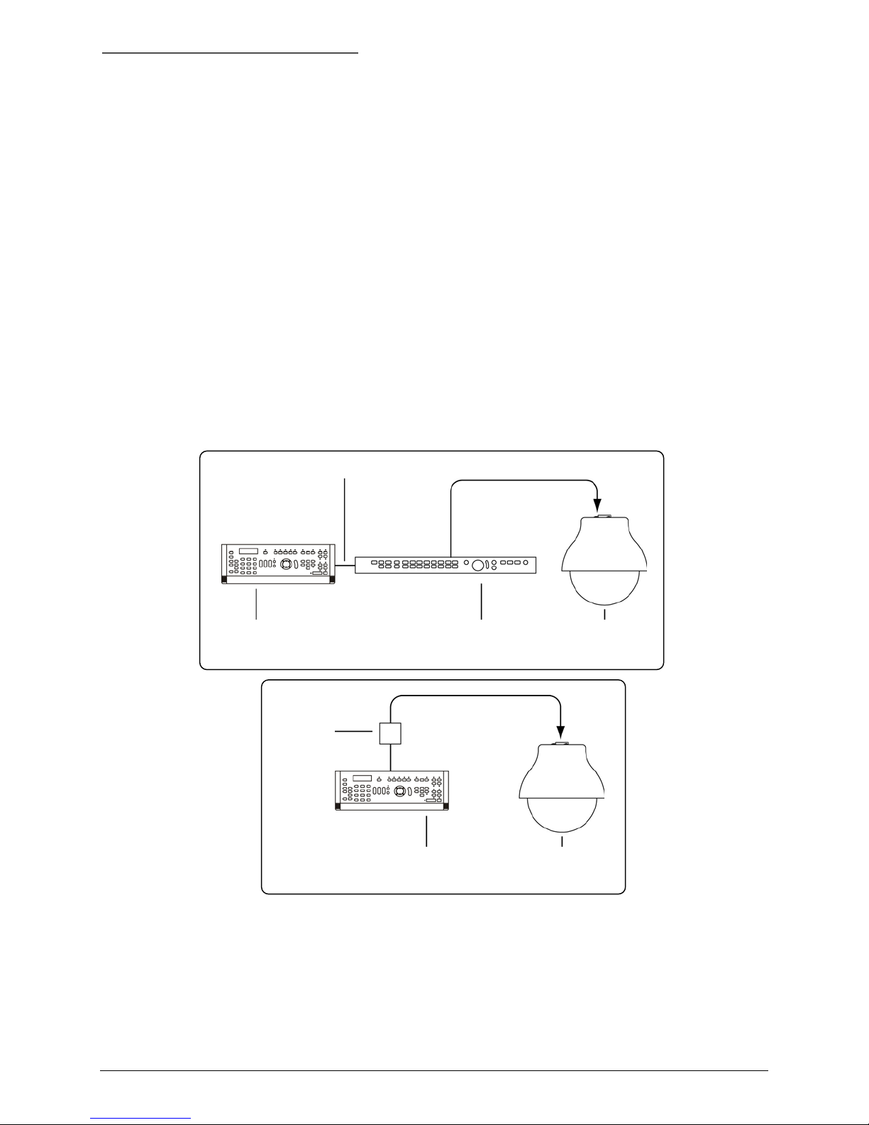
1.2 OPERATION REQUIREMENTS
The PowerDome has three built-in receivers, two for RS485, PowerDome, and Pelco D, and one for
coaxial UTC control. The dome automatically detects the current protocol. UTC control requires a Vista
Triplex Columbus hard disk recorder and a minimum of one keyboard. See Figure 1. A minimum of one
keyboard is required for RS485 control. See Figure 2.
Note: This manual does not cover Pelco D control.
RS485 UTC
Keypad Vista Columbus digital recorder PowerDome
Figure 1. Basic application with UTC control
I/O box
Keypad (RS485 control) PowerDome
Figure 2. Basic application with RS485 control
1.3 CABLE REQUIREMENTS
For RS485 operation, PowerDomes require video, power, and data cables.
The video cable carries the video signal to the remote viewing site. If sending video via coaxial
cable, a 75 Ω coaxial cable is typically used. If sending video via twisted-pair cable, use an
unshielded, CAT5 twisted-pair cable.
6 1040647A / July 2003
PowerDome Installation Manual Introduction
The 24VAC cable powers the PowerDome and the camera. To determine cable size, refer to the
Power Cable Size and Length subsection of the Introduction.
The RS485 control cable carries commands from the keypad to the PowerDome. An RS485
compatible shielded, two-conductor, twisted-pair cable is required. Recommended cable size is 22
gauge (0.64 mm).
Note: When using the UTP interface modules Vista recommends that you use only active receivers.
For UTC control, only a video coaxial cable is required.
1.4 POWER REQUIREMENTS
CAUTION:
For optimal video performance, all PowerDomes must be powered from an isolated 24 VAC power
source—fused outputs are not adequate. Allowable voltage range is 20 to 28 V.
All domes require a 24 VAC power supply that provides isolated outputs to operate the domes’ pan/tilt
drive, camera, and heater/fan (if applicable). The total power requirement varies depending on the model
of the PowerDome.
Dome power requirements (at 24 VAC):
All domes without a heater/fan require 20 VA
7 inch domes with heater/fan require 55 VA
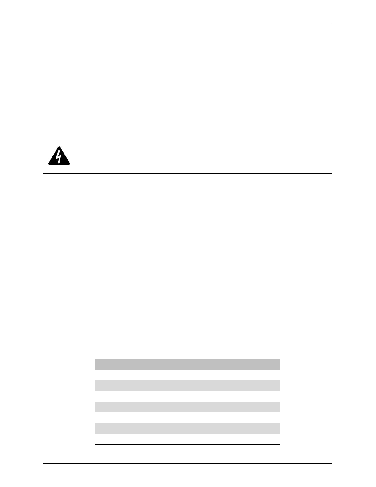
1.5 POWER CABLE SIZE AND LENGTH
It is important to choose the proper gauge of the cable that supplies 24 V to the PowerDome. An
inadequate gauge will cause a voltage drop resulting in improper operation.
Table 1 gives the recommended cable lengths of varying wire gauges for a PowerDome with a colour
camera. Note that the heater and fan reduces maximum cable length substantially.
Table 1. Maximum power cable lengths
Wire Gauge
(AWG) (mm2) Feet Meters Feet Meters
10 2.60 1443 440 525 160
12 2.05 906 276 329 100
14 1.62 569 173 207 63
All Domes
without Heater/Fan
(20 VA)
7 inch Domes
with Heater/Fan
(55 VA)
16 1.29 358 109 130 40
18 1.02 225 69 82 25
20 0.81 142 43 52 16
22 0.64 89 27 32 10
1040647A / July 2003 7
Housing Installation PowerDome Installation Manual
2 HOUSING INSTALLATION
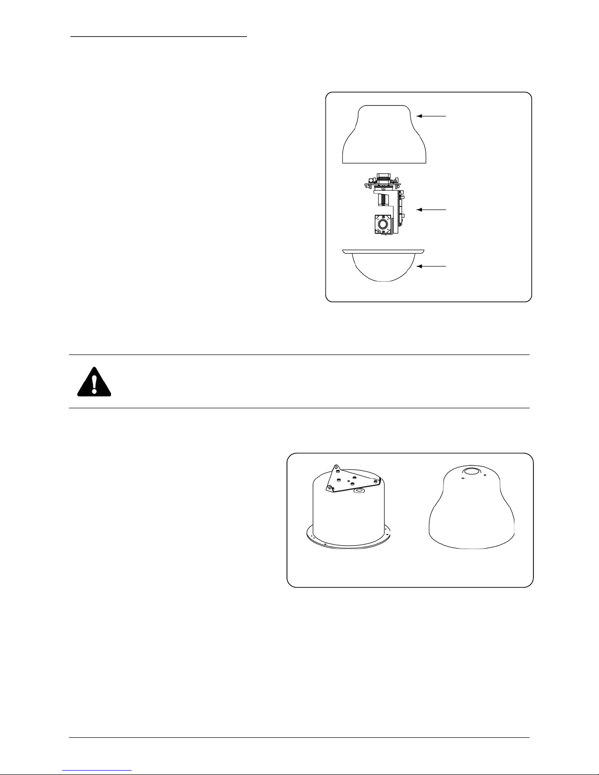
A complete PowerDome consists of an upper housing, a
pan/tilt assembly with a built-in receiver and camera, and
an acrylic dome. See Figure 3.
In General: The method of installation depends on
which upper housing is being used. Installation involves
securing the upper housing, making cable connections,
mounting the pan/tilt assembly, and fastening the acrylic
dome.
The Interface Module: Make all PowerDome cable
connections (video, RS485, and 24 VAC) to an interface
module. There are two types of interface modules: one is
for coaxial video, and the other is for UTP video
transmission. When you send video via coaxial cable,
make the connections to a coaxial interface module.
When you send video via unshielded twisted-pair (UTP)
cable, make connections to a UTP interface module.
Figure 3. PowerDome components
Upper housing
Pan/tilt assembly
Dome
Note: Vista recommends that you use only active receivers with the UTP interface modules.
CAUTION:
For safety reasons, all mechanical components used to support the PowerDome 6 inch flush-mount and
7 inch pendant-mount assembly must be able to support a 16 kg (35 lb) load.
There are separate sections for the installation procedures for each housing style.
These installation instructions address two
upper housing styles (See Figure 4).
To install the 6 inch flush-mount housing
see section 2.1, 6 inch Flush-Mount
Housing Installation Using the VPD-T600.
To install the 7 inch pendant-mount
housing see section 2.2, 7 inch PendantMount Housing Installation.
6 inch Flush-Mount 7 inch Pendant-Mount
Figure 4. Housing styles
8 1040647A / July 2003
PowerDome Installation Manual Housing Installation
2.1 6 INCH FLUSH-MOUNT HOUSING INSTALLATION USING THE VPD-T600
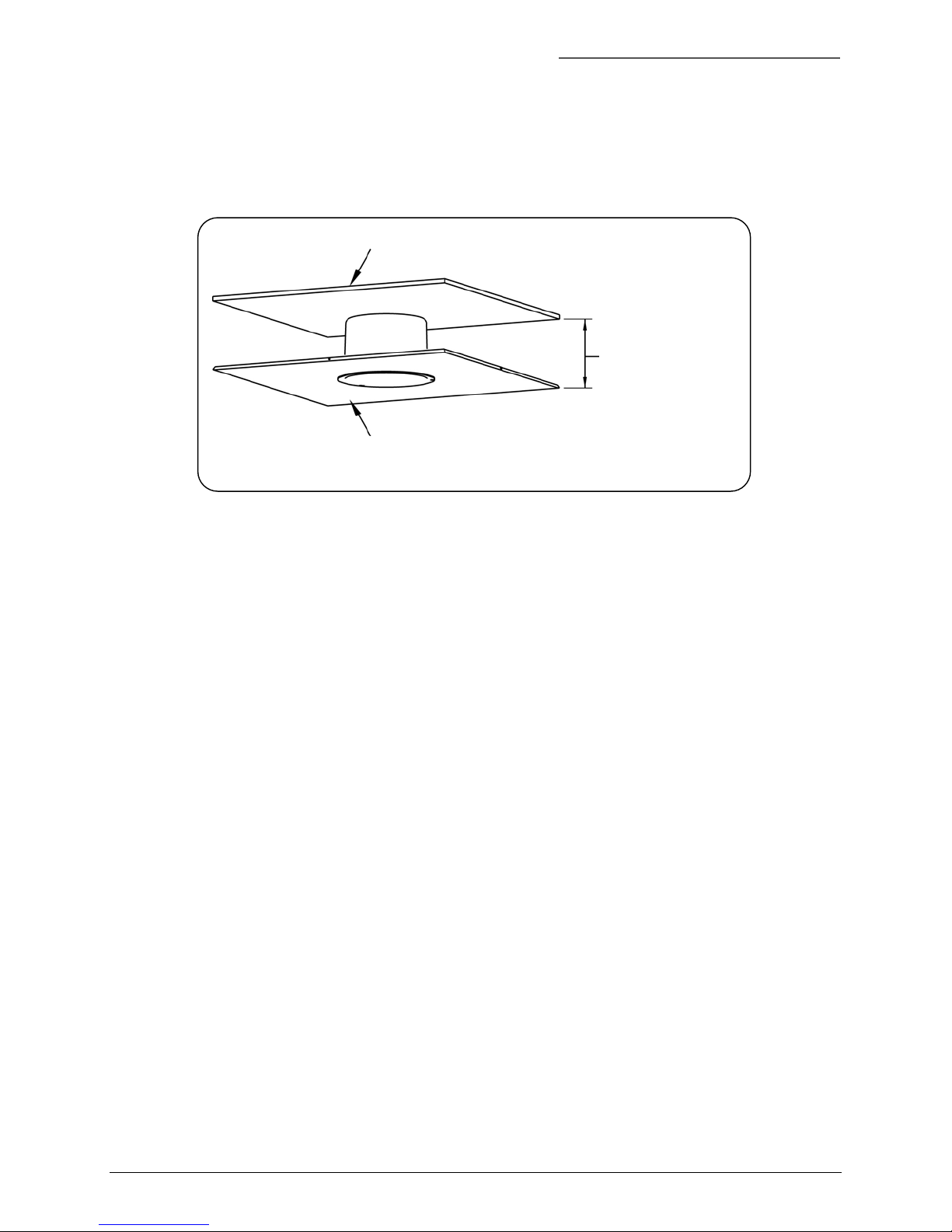
Install the 6 inch flush-mount housing into ceilings with removable 600 x 600 mm or 600 x 1200 mm
ceiling panels, provided there is sufficient clearance for the unit. See Figure 5.
Top of ceiling cavity
False ceiling
Figure 5. False ceiling clearance
15.88 cm (6.25 in)
minimum clearance
The VPD-T600 is a T-bar support kit for mounting a flush-mount dome in an existing ceiling panel. The
T-bar support kit distributes the weight of the dome to the panel braces via support brackets. Each kit
comes with one ceiling ring, T-bar supports, and mounting hardware.
1040647A / July 2003 9
Housing Installation PowerDome Installation Manual
2.1.1 INSTALLING THE HOUSING
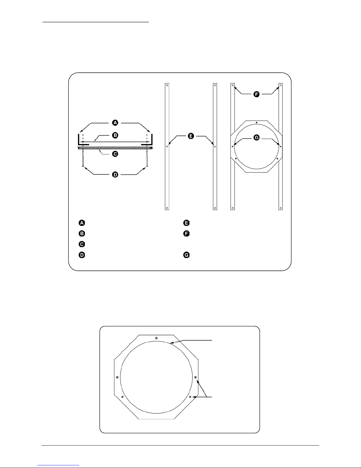
To prepare the ceiling panel see Figure 6 and perform the following.
T-bar supports T-bar bracket mounting holes
Ceiling ring
Ceiling
Flathead screws (provided) Ceiling ring mounting holes
Figure 6. Installing the T-bar support kit with ceiling ring
Use these holes to attach to panel
braces
1) Remove the appropriate ceiling panel.
2) Hold the ceiling ring in the desired location on the tile with the flat surface facing away from the
panel.
3) Use a pencil to trace the inside of the ceiling ring and to mark all five fastener hole locations.
Trace inside of
ring
Figure 7. Using the ceiling ring as a template
10 1040647A / July 2003
Mark fastener
holes (5)

PowerDome Installation Manual Housing Installation
4) Using a 5 mm drill bit, drill all five fastener holes. Ensure that all holes are drilled perpendicular to
the panel.
5) Cut a hole in the panel using the penciled tracing as a guide.
To attach the kit to the panel and install the panel, perform the following.
1) Place the long side of the T-bar support brackets flush against the inside of the panel. Align the
mounting holes with the drilled holes in the panel.
2) Place the ceiling ring on the T-bar brackets with its smooth side down and its mounting holes
aligned with the mounting holes on the brackets.
3) Using the ceiling ring mounting holes, secure the ceiling ring in place with two of the flathead screws
provided. Tighten the screws enough to draw them flush with the panel surface.
4) Replace the ceiling panel with the attached T-bar support kit in its original location.
5) Attach the T-bar support to the panel braces using the holes provided.
1040647A / July 2003 11
Housing Installation PowerDome Installation Manual
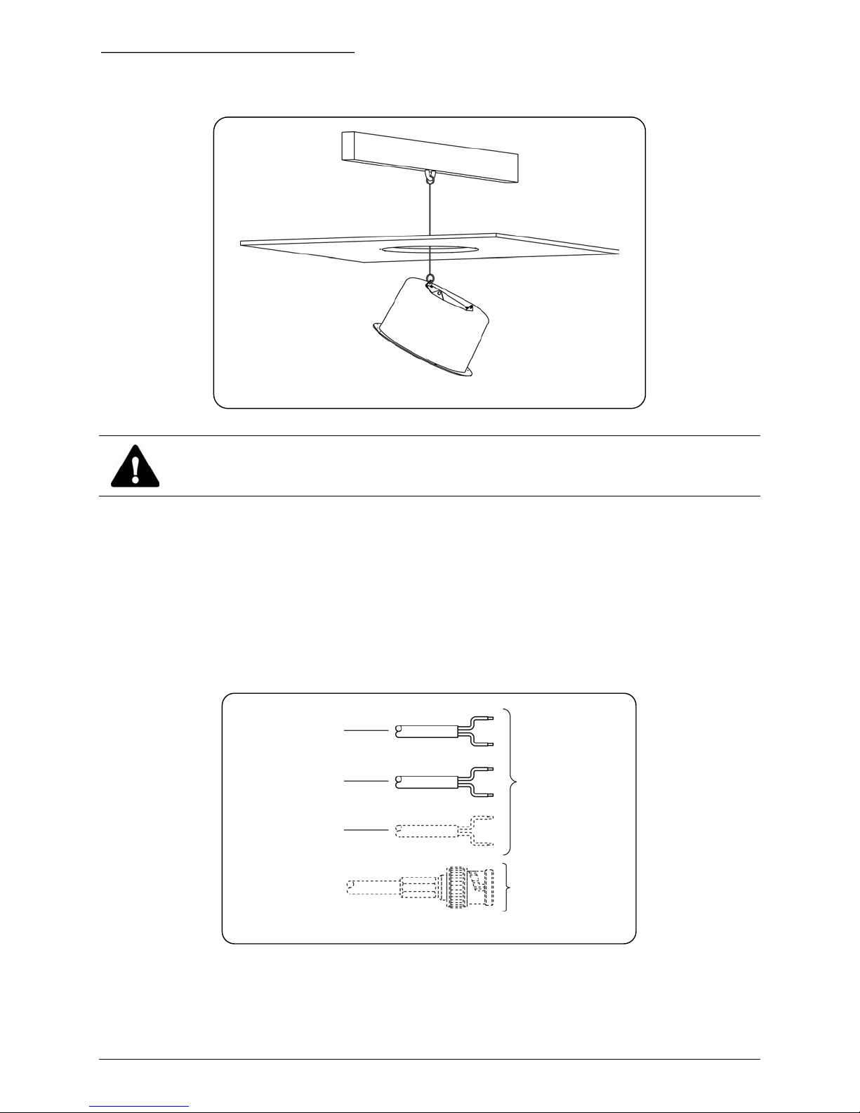
To attach the housing to the superstructure with safety cables see Figure 8 and perform the following.
Figure 8. Securing the housing to the superstructure with a safety cable.
CAUTION:
The safety cable must be able to support a 16 kg (35 lb) load.
1) Attach a metal safety cable to the ceiling’s superstructure and feed it through the mounting hole.
2) Attach the housing to the safety cable.
To make cable connections and complete the housing installation perform the following.
1) Feed the video, 24 VAC, and RS485 control cables through the ceiling to the vacated panel
location.
2) Prepare the cables as shown in Figure 9.
RS485
24 VAC
Twisted-pair video
(if used)
Coaxial video
(if used)
Strip ends of
wires
Terminate video
cable with BNC
Figure 9. Preparing cables
12 1040647A / July 2003
PowerDome Installation Manual Housing Installation
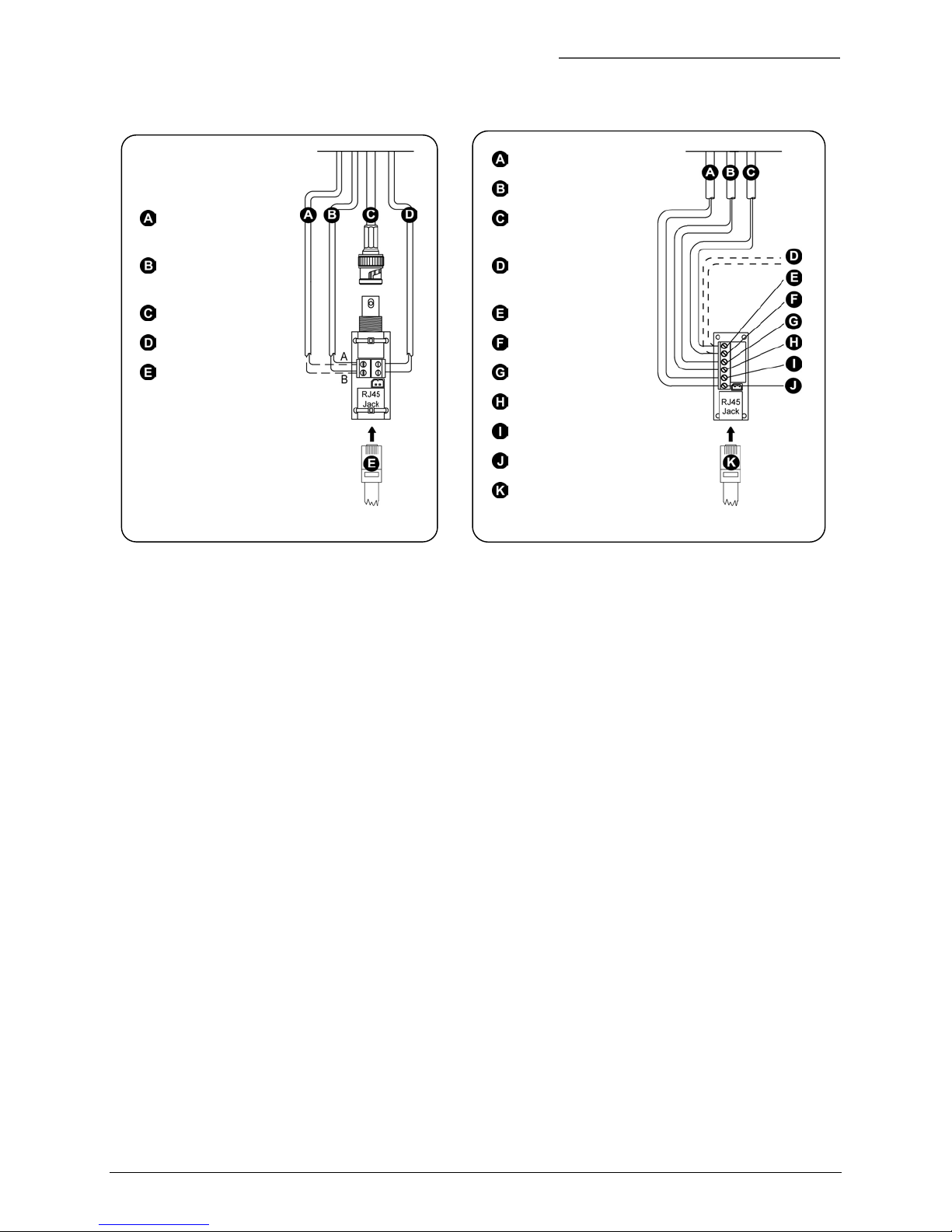
3) Make cable connections as shown in Figure 10 or Figure 11.
24 VAC
RS485 control
signal out (if used)
RS485 control
signal in
Video
24 VAC
RJ45
Figure 10. Coaxial interface module
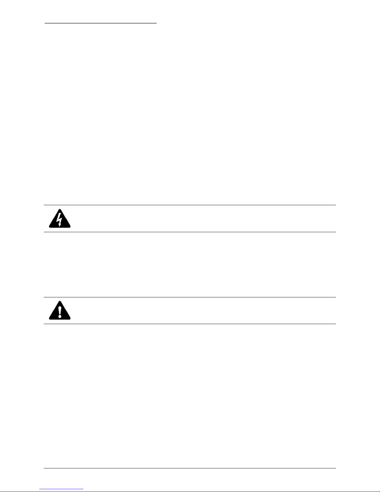
Twisted-pair video
RS485 control
signal in (data in)
RS485 control
signal out (if used)
Data in (+ or A)
Data in (- or B)
Video out (+)
Video out (–)
24 VAC (A)
24 VAC (B)
RJ45
Figure 11. UTP interface module
4) Push the upper housing through the hole and secure it with the three provided screws.
5) Reinstall any removed ceiling panels.
6) Proceed to section 3, PTZ and Dome Installation, on page 29.
1040647A / July 2003 13
Housing Installation PowerDome Installation Manual
2.2 7 INCH PENDANT-MOUNT HOUSING INSTALLATION
Install the 7 inch pendant housing with one of the following mounts.
VPD-WM Wall Mount. See section 2.2.1, Using the VPD-WM Wall Mount.
VPD-EWM Wall Mount. See section 2.2.2, Using the VPD-EWM Wall-Mount Bracket.
VPD-ESM Swing-Arm Mount. See section 2.2.3, Using the VPD-ESM Swing-Arm Mount.
2.2.1 USING THE VPD-WM WALL MOUNT
Attach the VPD-WM Wall Mount directly to a vertical surface or mate it with a VPD-CMA Corner-Mount
Bracket, a VPD-EPMA Pole-Mount Bracket, or a VPD-ERM Roof-Mount Bracket. See Appendix A for
mounting accessory installation instructions. The following instructions explain how to install the VPD-WM
Wall Mount directly to a vertical surface.
Note: Cables will usually come out of the mounting surface and enter the unit through the rear opening in the base. If the cables are
attached externally to the mounting surface and need to enter the unit through the side, see section 2.2.1.1, Creating a Conduit
Hole.
CAUTION:
Complete all instruction steps before supplying power to the unit.
To prepare the unit and mounting surface perform the following.
1) Loosen the two cover screws enough to remove the cover (removing the screws is not necessary).
See Figure 12.
2) Remove the cover and interface module. See Figure 12.
CAUTION:
To ensure the proper operation of an attached camera, mount the adapter level.
3) Place the unit against the vertical mounting surface, ensure that it is level, and then mark the
location of the four mounting holes and the center cable-entry opening. See Figure 13.
14 1040647A / July 2003

PowerDome Installation Manual Housing Installation
Figure 12. Removing the cover and interface module
Note: Mounting fasteners are not included.
Figure 13. Marking the mounting holes and cable entry
4) Prepare the mounting holes appropriately for the type of surface (concrete, wood, etc.) and
fasteners used.
CAUTION:
The hardware and procedure used to secure the unit must enable it to support at least 16 kg (35 lb).
5) If necessary, drill a pass-through hole in the mounting surface for cable entry.
6) Pull the video, 24 VAC, and RS485 cables from inside the mounting surface through the cable-entry
hole.
To mount the unit perform the following.
1) Securely mount the unit to the wall with the appropriate fasteners. See Figure 15 and Figure 14.
Figure 14. Mounting the unit
Minimum of 16 kg (35 lb)
Figure 15. Load requirement
2) Seal all mounting holes so that no moisture can leak into the mounting surface.
To wire and mount the interface module, perform the following.
1) Prepare the cables as shown in Figure 16.
1040647A / July 2003 15

Housing Installation PowerDome Installation Manual
RS485
24 VAC
Twisted-pair video
(if used)
Strip ends of
wires
Coaxial video
(if used)
Figure 16. Preparing cables
CAUTION:
Do not connect the 24 VAC power wires to the video or RS485 connections, because it will damage the
PowerDome.
Terminate video
cable with BNC
connector
2) Wire the interface module as shown in Figure 17.
VPD-WM UTP Interface Module VPD-WM Coaxial Interface Module
Cable(s) from VPD-WM Cable(s) from VPD-WM
24 VAC Coaxial video
24 VAC
Twisted pair video out (-) 24 VAC
Twisted pair video out (+) 24 VAC
RS485 data in (- or B) RS485 data in (- or B)
RS485 data in (+ or A) RS485 data in (+ or A)
Interconnect cable Interconnect cable
2-pin Molex connector
(optional heater/fan)
Figure 17. Connections to UTP and Coaxial VPD-WM interface modules
2-pin Molex connector
(optional heater/fan)
3) Insert the interface module into the mounting slot in the VPD-WM as shown in Figure 18.
16 1040647A / July 2003

PowerDome Installation Manual Housing Installation
Figure 18. Installing the interface module into the VPD-WM
4) Attach the VPD-WM cover with the hardware provided as shown in Figure 19.
Figure 19. Attaching the VPD-WM cover
CAUTION:
Before making connections to the housing, secure the safety chain on the housing to the safety clip
inside the VPD-WM Wall Mount. Do not remove the safety cable after housing is installed.
To attach the housing safety cable to the mount safety clip see Figure 20 and perform the following.
1) Slide a section of the safety cable into the groove in the safety clip.
Note: Ensure that the taut section of the safety chain is shorter than the interconnect cable. The safety chain—not the
interconnect cable—should bear the weight of the housing.
2) Lower the housing until the safety chain is taut to ensure that it is secure.
1040647A / July 2003 17

Housing Installation PowerDome Installation Manual
Figure 20. Attaching the PowerDome pendant safety chain to the VPD-WM safety clip
To make cable connections and attach the housing to the VPD-WM perform the following.
1) Insert the housing interconnect cable into the RJ45 jack on the VPD-WM interface module. See
Figure 21.
2) Connect the heater/fan power cable to the 2-pin Molex connector on the VPD-WM interface module.
See Figure 21.
3) Guide the flange of the housing into the collar of the VPD-WM and fasten the housing to the mount
using the provided screws. See Figure 22.
Option heater power Interconnect cable
Figure 21. Connecting the PowerDome to the
VPD-WM interface module
Figure 22. Securing the PowerDome housing to the
VPD-WM.
4) To install the optional heater/fan assembly see Appendix B.
18 1040647A / July 2003

PowerDome Installation Manual Housing Installation
2.2.1.1 CREATING A CONDUIT HOLE
To create a side conduit hole in the unit, see Figure 23 and Figure 24 and perform the following.
Template
Figure 23. Marking the pilot hole
3.5 mm (1/8 in.)
Figure 24. Drilling a side conduit hole
9.5 mm (3/8 in.)
13 mm (1/2 in.)
23 mm (7/8 in.)
1) Align the provided template with the side of the unit.
2) Mark the center of the template’s drill hole.
CAUTION:
To maintain material integrity, do not drill the conduit hole. Start with a pilot hole and enlarge it until a
knockout punch can be used to achieve the final hole size. (Hole sizes are given below.)
3) Drill a 3.5 mm (1/8 inch) pilot hole.
4) Enlarge the pilot hole to 9.5 mm (3/8 inch).
5) Use a 13 mm (1/2 inch) conduit knockout punch to enlarge the hole to 23 mm (7/8 inch).
1040647A / July 2003 19

Housing Installation PowerDome Installation Manual
2.2.2 USING THE VPD-EWM WALL-MOUNT BRACKET
Attach the VPD-EWM Wall Mount directly to a vertical surface or mate it with a VPD-CMA Corner-Mount
Bracket, a VPD-EPMA Pole-Mount Bracket, or a VPD-ERM Roof-Mount Bracket. See Appendix A for
mounting accessory installation instructions. The following instructions explain how to install the VPDEWM Wall Mount directly to a vertical surface.
CAUTION:
Complete all instruction steps before supplying power to the unit.
Note: Typically, cables feed out of the mounting surface and enter the wall mount unit through the rear opening in the base. If the
cables will attach externally to the mounting surface and enter the unit through the side of the unit, see 2.2.1.1 to open a side-entry
conduit hole in the unit.
Note: The factory secures the end of the safety chain with a quick tie to the dome opening as shown in Figure 25. To keep the
safety chain from slipping back into the wall mount, do not free the safety chain until you connect it to the dome.
To prepare the unit and mounting surface perform the following.
1) Remove the cable access cover from the mount. See Figure 26.
CAUTION:
To ensure the proper operation of an attached camera, mount the adapter level.
2) Place the unit against the vertical mounting surface, ensure that it is level, and then mark the
location of the four mounting holes and the outline of the cable access opening. See Figure 27.
Quick tie Safety chain fed through mount
Figure 25. Factory-attached safety chain
Figure 26. Removing the cable access cover
20 1040647A / July 2003
Figure 27. Leveling the unit and marking the mounting
holes and cable access opening onto the mounting
surface

PowerDome Installation Manual Housing Installation
3) Prepare the mounting holes appropriately for the type of surface (concrete, wood, etc.) and
fasteners used.
Note: Mounting fasteners are not included.
CAUTION:
The hardware and procedure used to secure the unit must enable it to support at least 16 kg (35 lb).
See Figure 29.
4) If necessary, drill a cable pass-through hole within the outline of the cable access opening on the
mounting surface.
To mount the unit see Figure 28 and perform the following.
1) Securely mount the unit to the wall with the appropriate fasteners. Seal all mounting holes so that
no moisture can leak into the mounting surface.
Mounting
fasteners (4)
Figure 28. Mounting the unit
Figure 29. Load requirement
Minimum 16 kg (35 lb).
2) Pull the video, 24 VAC, and RS485 cables from inside the mounting surface through the cable passthrough hole.
3) Attach the dome housing to the end of the safety chain as shown
in Figure 30.
4) Cut the safety chain quick tie so the housing hangs freely from the
mount.
5) Feed the cables from the dome housing down through the mount
to the cable access opening.
6) Secure the housing to the mount using the three 10-32x3/8 screws
provided.
Figure 30. Attaching the dome
housing to the safety cable
Cables
1040647A / July 2003 21

Housing Installation PowerDome Installation Manual
To make the cable connections perform the following.
1) Prepare the cables as shown in Figure 31.
RS485
24 VAC
Twisted-pair video
(if used)
Strip ends of
wires
Coaxial video
(if used)
Figure 31. Preparing cables
CAUTION:
Do not connect the 24 VAC power cable to the video or RS485 connection because it will damage the
PowerDome.
Note: There are two versions of the PowerDome interface module depending on whether video is being sent via coaxial
cable (PowerDome Coaxial Interface Module) or unshielded twisted-pair (UTP) wire (PowerDome UTP Interface Module).
See Figure 32 or Figure 33.
Terminate video
cable with BNC
connector
2) Make the cable connections to the interface module. Allow approximately 76 mm (3 in.) of cable for
connections.
3) Insert the PowerDome interconnect cable into the RJ45 jack on the interface module. See Figure 32
or Figure 33.
4) Connect the heater/fan power cable to the 2-pin Molex connector on the module. See Figure 32 or
Figure 33.
22 1040647A / July 2003

PowerDome Installation Manual Housing Installation
RS485 control
signal out (if used)
RS485 control
signal in
Video
24 VAC
RJ45
Heater/fan
Figure 32. Coaxial interface module
24 VAC
Twisted-pair video
RS485 control
signal in (data in)
RS485 control
signal out (if used)
Data in (+ or A)
Data in (- or B)
Video out (+)
Video out (–)
24 VAC (A)
24 VAC (B)
Heater/fan
RJ45
Figure 33. UTP interface module
5) Push the cables and interface module back into the cable access opening.
6) Reinstall the cable access opening cover.
7) To install the optional heater/fan assembly see Appendix B.
2.2.2.1
CREATING A CONDUIT HOLE
To create a side-entry conduit hole in the wall mount see Figure 34.
1. Use the existing dimple as a guide to
drill a 9.5 mm (3/8 in.) pilot hole
Figure 34. Creating the conduit hole
2. Enlarge the 9.5 mm pilot hole
to a 23 mm (7/8 in.) hole
1040647A / July 2003 23

Housing Installation PowerDome Installation Manual
2.2.3 USING THE VPD-ESM SWING-ARM MOUNT
To install the 7 inch pendant housing with the VPD-ESM Swing-Arm Mount, see Figure 35 and perform
the following procedures.
Dome screws
Collar
UTP interface module
Coaxial interface module
Swing arm
Mounting holes
Figure 35. VPD-ESM assembly hardware
24 1040647A / July 2003
Mounting socket
Mounting plate
Pem nut
Junction box
Pivot locking screws
Nipple (1/2 conduit)
Junction box screw
Gasket
Junction box cover
Junction box cover screws
Twisted-pair wire terminal
connections inside junction box cover

PowerDome Installation Manual Housing Installation
CAUTION:
Complete all instruction steps before supplying
power to the unit.
To install the mounting plate perform the following.
1) Remove the junction box from the mounting plate.
2) Place the mounting plate against the vertical
mounting surface, level the plate, and then mark the
location of the four corner mounting holes. (Use all
six mounting holes for extra support, as needed.)
See Figure 36.
3) Prepare the mounting holes in accordance with the
type of surface (concrete, wood, etc.) and fasteners
used.
Note: Mounting fasteners are not included.
CAUTION:
For safety, the hardware and procedure used for
securing the top plate must enable it to support a
minimum of a 16 kg (35 lb) load. See Figure 37.
4) Attach the mounting plate to the vertical mounting
surface with the appropriate fasteners. Make sure the
plate is oriented such that the socket is up and the
junction box is down.
Figure 36. Marking mounting holes
Minimum of 16 kg (35 lb)
Figure 37. Minimum load requirement of swing-arm
mount
5) Properly seal all mounting holes that could cause
leaks into the mounting surface.
To install the swing arm perform the following.
1) Slide the swing arm into the mounting socket and
securely tighten the pivot locking screws. See
Figure 38. Position the arm such that the collar is
accessible from the rooftop for mounting the dome.
Note: The swing arm comes with the cable assembly installed and
tacked down at both ends of the arm. You might have to free the
end going through the mounting socket.
Figure 38. Attaching the swing arm to the mounting
socket
1040647A / July 2003 25

Housing Installation PowerDome Installation Manual
2) Feed the end of the cable assembly coming out of the mounting socket through the nipple on the
top of the junction box. See Figure 39.
Note: Feed the video cable BNC connector through the nipple first and then the twisted-pair bundle.
3) Remount the junction box onto the mounting plate using the hardware provided. See Figure 40.
Figure 39. Cable assembly into the chase nipple
Figure 40. Remounting the junction box
To make cable connections perform the following.
1) Place the sealing gasket on the inside of the junction box cover, and then make the cable assembly
connections to the terminal strip. See Figure 41.
2) WITH POWER OFF, make the facilities connections to the terminal strip on the inside of the junction
box cover. See Figure 41.
Twisted-pair wire
from inside junction box
Used if video sent via
twisted-pair wire
Sealing gasket
Swing arm connections
Facility connections
Coaxial cable
from inside junction box
Used if video sent via
coaxial cable
Figure 41. Cable assembly connections in the junction box
3) Install the junction box cover. Ensure that the sealing gasket is properly positioned.
26 1040647A / July 2003

PowerDome Installation Manual Housing Installation
CAUTION:
Do not connect the 24 VAC power cable to the video or RS485 connection because it will damage the
PowerDome.
4) Attach the interface connector card (provided with the PowerDome) to the cable assembly.
Note: Vista recommends that you use only active receivers with the UTP interface modules.
5) Bring the housing near the end of the swing arm and insert the PowerDome’s interconnect cable
into the RJ45 jack on the interface module. See Figure 42 or Figure 43.
6) Connect the heater/fan power cable to the 2-pin Molex connector on the module. See Figure 42 or
Figure 43.
RS485 control
signal out (if used)
RS485 control
signal in
Video
24 VAC
RJ45
Heater/fan
Figure 42. Coaxial interface module
24 VAC
Twisted-pair video
RS485 control
signal in (data in)
RS485 control
signal out (if used)
Data in (+ or A)
Data in (- or B)
Video out (+)
Video out (–)
24 VAC (A)
24 VAC (B)
Heater/fan
RJ45
Figure 43. UTP interface module
1040647A / July 2003 27

Housing Installation PowerDome Installation Manual
To complete the mount installation perform the
following.
1) Push the cables and interface module back
into the swing arm, guide the flange of the
housing into the collar of the swing arm
(matching up the mating holes), and fasten
the housing to the swing arm using the three
10-32x3/8 screws provided. See Figure 44.
2) To install the optional heater/fan assembly
see Appendix B.
Note: After the PTZ assembly and dome are installed,
loosen the pivot locking screws on the mounting socket
and swing the swing arm (with PowerDome attached) out
to the desired position, and again securely tighten the
pivot locking screws.
Figure 44. Connecting the housing to the swing arm
28 1040647A / July 2003

PowerDome Installation Manual PTZ and Dome Installation
3 PTZ AND DOME INSTALLATION
To set RS485 termination see section 3.1, RS485 Termination.
To install the pan/tilt assembly see section 3.2, Installing the Pan/Tilt Assembly.
3.1 RS485 TERMINATION
See Figure 45 and perform the following.
1) Locate the red, sliding termination switch on the PC board at the top of the housing.
2) If the RS485 control cable connected to the PowerDome does not loop out to another unit (i.e., it is
the final receiver location) or you are connecting a VPD-ALM16 alarm module to a UTC controlled
dome, place the switch in the ON position.
3) Apply 24 VAC power to the housing. The housing’s red LED power indicator lamp should illuminate. It
is located on the underside of the PTZ bracket.
Figure 45. Setting the line termination switch
3.2 INSTALLING THE PAN/TILT ASSEMBLY
This section gives detailed procedures for installing the PowerDome’s motorized pan/tilt
assembly. Installation involves securing the pan/tilt assembly to the upper housing and setting the
receiver’s DIP switch.
1040647A / July 2003 29
On Off

PTZ and Dome Installation PowerDome Installation Manual
See Figure 46 and perform the following.
Figure 46. Installing the PTZ assembly
1) Insert the safety catch ( ) though the channel in the retaining bracket ( )
attached to the upper housing.
Note: When completing the next step, the PowerDome will move (become active) in both the pan and tilt directions, as part of
its orientation protocol.
2) Push the spring latch handle ( ) outward while pivoting the pan/tilt assembly up until it is vertical.
3) Secure the pan/tilt assembly by releasing the latch handle and engaging the catch tab (
4) Check to ensure that the four plastic mounting studs (
).
(
) are mated with the four alignment holes
).
30 1040647A / July 2003

PowerDome Installation Manual PTZ and Dome Installation
3.3 SETTING THE SITE ADDRESS DIP SWITCH
The receiver card mounted on the PowerDome’s pan/tilt assembly contains a multi-position DIP switch.
See Figure 47. Use the switch to assign a camera number to the PowerDome.
Receiver card
Site address DIP switch
Figure 47. Location of site address DIP switch
To program the receiver’s site number on the DIP switch see Table 2 and Appendix C.
Table 2. DIP switch positions and equivalent values
DIP Switch Position Number 1 2 3 4 5 6 7 8 9 10 11 12
Equivalent Value 1 2 4 8 16 32 64 128 256 512 X X
X = Not Used
If you use the PowerDome with coaxial UTC telemetry, we recommend that you set the address
especially if you plan to add a VPD-ALM16 alarm module.
If you use RS485 directly from a Vista NPX/KBD/J3De or VPD-KBD keyboard that is also controlling
multiple Vista Triplex Columbus digital recorders or VDC1604 matrix units, address domes attached to
the units as follows:
Unit with BaxNet address 1: 1 through 16
Unit with BaxNet address 2: 17 through 32
Unit with BaxNet address 3: 33 through 48
Unit with BaxNet address 4: 49 through 64
For units with any other BaxNet address, domes should be numbered 1 through 16 and you should use
only one keyboard.
When you use UTC control, each receiver needs to tune to the transmitter. Select each dome in turn, and
pan left and right until the dome moves. This should take about 5 to 10 seconds.
1040647A / July 2003 31

PTZ and Dome Installation PowerDome Installation Manual
3.4 INSTALLING THE DOME ASSEMBLY
The PowerDome comes with one of four acrylic
dome assembly options: bronze, clear, smoke,
chrome mirror, gold mirror, polycarbonate clear,
or polycarbonate smoke. Each dome assembly
attaches to the upper housing with interlocking
clips and a dome safety cable. Always take great
care not to damage the dome’s surfaces. Protect
the dome from dust and do not place it face
down on any surface.
Safety clip
7 inch pendant-mount housing
CAUTION:
Do not touch the acrylic when handling
the dome assembly. Use a scratchresistant cloth.
To attach the dome assembly to flush- and
pendant-mount housings:
1) Fasten the dome safety cable to the upper
housing with the safety clip. See Figure 48.
2) Position the dome such that the angled ends
of its mounting clips face the angled ends of
the clips attached to the upper housing.
3) Turn the acrylic dome clockwise, so that the
ends of the mounting clips engage and lock
into place.
Safety
Mounting
clips
cable
Flush-mount housing
Safety
clips
Safety
cable
Mounting
clips
Figure 48. Attaching the dome assembly to the upper housing
32 1040647A / July 2003

PowerDome Installation Manual Programming and Operating the PowerDome
4 PROGRAMMING AND OPERATING THE POWERDOME
Note: To ensure that unit(s) are operating properly, test the pan, tilt, and lens functions once each week.
PowerDomes come equipped with a variety of camera options, and each camera’s programming varies
depending on available functions. Refer to the PowerDome Programming Instructions manual for
programming instructions for any PowerDome.
Control the PowerDome units with either of Vista’s NPX/R/KDB/J3De or VPD-KBD controller keypads.
Refer to the corresponding keypad manual for instructions on operating all PowerDomes.
1040647A / July 2003 33

Appendix PowerDome Installation Manual
APPENDIX A: MOUNTING ACCESSORIES
VPD-FCA FIXED CAMERA ADAPTER
The VPD-FCA camera adapters install into PowerDome flush or pendant housings. Units come packaged
from the factory pre-wired with video and power cables.
To install the bracket see Figure 49 and perform the following.
Figure 49. Installing the fixed camera adapter
1) Attach the camera and lens to the fixed assembly with the appropriate mounting screw and lock
washer.
2) Insert the safety catch (
housing.
3) Push the spring latch handle (
4) Secure the pan/tilt assembly by releasing the latch handle and engaging the catch tab (
5) Check to ensure that the four cap nuts (
6) Adjust the camera to the desired position.
7) If necessary, move the camera forward on the bracket so that the lens will be located closer to the
lower dome.
) though the channel in the retaining bracket ( ) attached to the upper
) outward while pivoting the pan/tilt assembly up until it is vertical.
).
) are mated with the four plastic nuts ( ).
34 1040647A / July 2003

PowerDome Installation Manual Appendix
VPD-CMA CORNER-MOUNT ADAPTER
CAUTION:
For safety, the hardware and procedure used for securing the VPD-CMA must enable it to support a
minimum of a 16 kg (35 lb) load.
To use the VPD-CMA Corner-mount Bracket to mount
a VPD-WM or VPD-EWM Wall Mount to the corner of
a building see Figure 50 and perform the following.
1) Place the adapter on the corner of the building
and mark the location of the four mounting holes.
2) Prepare the four mounting holes in accordance
with the type of wall (concrete, wood, etc.) and
fasteners used.
3) Secure the adapter to the wall with the
appropriate fasteners.
4) Attach the wall mount to the bracket mounting
holes on the adapter using the hardware provided.
Figure 50. Corner-mount adapter installation
Mounting
holes (4)
Bracket
mounting
holes
VPD-EPMA POLE-MOUNT ADAPTER
The VPD-EPMA Pole-Mount Adapter is used to attach various wall-mount brackets or an outdoor power
supply to a pole. The adapter can be bolted to a pole or secured with three adjustable stainless steel
bands.
CAUTION:
For safety, the hardware and procedure used to attach this unit must support the weight of the unit and
at least 16 kg (35 lb).
CAUTION:
To ensure the proper operation of an attached camera, mount the adapter level.
INSTALLING THE ADAPTER WITH BOLTS
1) Drill a cable pass-through hole in the pole.
2) Ensure that the adapter is level and that its center hole is lined up with the pass-through hole in the
pole.
3) Use the adapter as a template to mark the location of the two mounting holes. See Figure 51.
4) Drill and prepare the mounting holes for the type of pole and fasteners (not provided) being used.
Note: The fasteners used must ensure that the adapter supports the minimum weight requirements stated in the caution
statement.
1040647A / July 2003 35

Appendix PowerDome Installation Manual
5) Attach the adapter to the pole with the appropriate fasteners. See Figure 52.
6) To install mounts (Figure 53) or power supplies, see the appropriate installation instructions.
Figure 53. VPD-WM attached to
pole-mount adapter
Figure 51. Marking the mounting
holes
Figure 52. Bolting the adapter to a
pole
INSTALLING THE ADAPTER WITH BANDS
1) Drill a cable pass-through hole in the pole.
2) Ensure that the adapter is level and that it’s center hole is
lined up with the pass-through hole in the pole.
3) Secure the adapter to the pole by tightening the barrel screw
on each of the three stainless steel bands (not provided).
See Figure 54.
Note: The bands used must ensure that the adapter supports the minimum
weight requirements stated in the caution statement.
4) To install accessories or power supplies, see the appropriate
installation instructions document.
VPD-ERM ROOF-MOUNT ADAPTER
The VPD-ERM Roof-Mount Adapter is designed to combine with
the VPD-EWM or VPD-WM on the roof or parapet of a building.
The roof-mount adapter is hinged to allow the PowerDome to pivot over the roof for safe servicing.
Figure 54. Banding the adapter to a pole
36 1040647A / July 2003

PowerDome Installation Manual Appendix
To install the roof-mount adapter see Figure 55, Figure 56, and Figure 57 and perform the following.
Cover screw Hinge
Tab (screw hole) Mounting slots (6)
Figure 55. Attaching the adapter to the roof
Figure 56. Closing the adapter, shown with
VPD-WM
Screw hole (in tab) Mounting slots (6)
Figure 57. Base dimensions of roof-mount adapter
1) Remove the cover screw from the top of the VPD-ERM and open the bracket.
2) Locate the six mounting slots on the base of the bracket.
3) Place the Roof-mount Adapter on the edge of the roof or parapet, and mark the location of the
mounting slots.
4) Prepare the mounting slots in accordance with the type of wall (concrete, wood, etc.) and fasteners
used.
CAUTION:
For safety, the hardware and procedure used for securing the VPD-ERM must enable it to support a
minimum of a 16 kg (35 lb) load.
5) Secure the adapter to the roof or parapet with the appropriate fasteners.
6) Properly seal all mounting holes that could cause leaks into the roof structure.
7) Route the power, RS485, and video cables through the VPD-ERM, leaving enough cable to attach
the cables to the inside of the roof-mount adapter and continue them through the VPD-EWM Wall
Mount and into the camera housing.
1040647A / July 2003 37

Appendix PowerDome Installation Manual
8) Attach the wall mount to the roof-mount adapter.
9) Attach the pendant-mount housing to the VPD-EWM according to section 2.2.2, Using the VPD-
EWM Wall-Mount Bracket.
10) Close the VPD-ERM Roof-Mount Adapter and secure it with the cover screw.
38 1040647A / July 2003

PowerDome Installation Manual Appendix
APPENDIX B: HEATER/FAN ASSEMBLY
The heater/fan assembly is standard on the VPD-2WP series pendant PowerDomes. The fan is packed
separately for shipment. The heater comes attached to the ceiling of the housing with its power
connections made.
CAUTION:
One power input is used for both the PowerDome and the heater/fan. See Table 1, Maximum power
cable lengths, on page 7, to determine the size and length of the power cable. If the cable used is too
small, the voltage drop across the power line might be excessive and affect the operation of the
PowerDome.
To install the fan onto the PowerDome pan/tilt mechanism see Figure 58 and perform the following.
Screw slots
Side PC card
connector
Fan
assembly
Figure 58. Installing the heater/fan
Fan power
plug
1) Remove the PowerDome pan/tilt mechanism and fan assembly from their packaging.
2) Locate the two 4-40 x 1/4 inch screws shipped with the fan assembly.
3) Position the fan assembly and fasten it to the pan/tilt mechanism using the two 4-40 x 1/4 inch
screws.
4) Plug the fan motor into the side PC card.
5) Before installing the unit into the housing, to determine the appropriate size and length of the power
cable see Table 1, Maximum power cable lengths, on page 7.
1040647A / July 2003 39

Appendix PowerDome Installation Manual
APPENDIX C: ASSIGNING DIP SWITCH VALUES
One way to determine which switches to use is to subtract the highest possible switch value from the
address you want, then subtract the highest possible switch value from that difference. Continue to
subtract the highest possible switch value from the difference until you have zero. For example, if you
want address 53:
Switch Address 53
53
21 – 16 = 5 5
5 – 4 = 1 3
1 – 1 = 0 1
Switch
Value
– 32 = 21
Difference
Switch
On
6
Switch
values
Switch
numbers
Zone address 53 (1 + 4 + 16 + 32)
Figure A1. Switch values
Therefore, for address 53, you would use switches 1 (1), 3 (4), 5 (16), and 6 (32).
40 1040647A / July 2003

PowerDome Installation Manual Appendix
APPENDIX D: POWER SUPPLIES
VPD-PSU2 OUTDOOR POWER SUPPLY
The VPD-PSU2 is a 24 VAC outdoor power supply
designed for use with a pendant-mount weatherproof
PowerDome. It provides enough power (100 VA) to operate
the dome’s pan/tilt drive, camera, and heater/fan. The
VPD-PSU2 can be attached directly to a wall, or it can be
mounted on to either the VPD-CMA Corner-Mount Bracket
or the VPD-EPMA Pole-Mount Bracket. Fasteners are
provided for all applications.
Watertight
screws
1) Loosen the four watertight screws and remove the
cover. See Figure 59.
2) To attach the unit directly to a wall, mark the location
of the four mounting holes using the dimensions
shown in Figure 60. Prepare the four mounting holes
in accordance with the type of wall (concrete, wood,
etc.) and fasteners.
3) Mount the VPD-PSU2 with the appropriate fasteners
directly to the wall or to the VPD-CMA or VPD-EPMA
brackets as shown in Figure 61.
4) Make the cable connections as shown in Figure 62.
5) Replace the cover and tighten the screws securely to
ensure a watertight seal.
Figure 59. Loosen watertight screws to open cover
Figure 60. VPD-PSU2 mounting dimensions
Figure 61. Mounting the VPD-PSU2 to corner- and pole-mount brackets
1040647A / July 2003 41

Appendix PowerDome Installation Manual
Power
in
24 VAC out
Figure 62. VPD-PSU2 cable connections
Note: In case of a fuse failure, always replace an IRT with a fuse of the same type and value.
Live / Brown
Neutral / Blue
Earth / Y&G
Red
Red
42 1040647A / July 2003

PowerDome Installation Manual Appendix
APPENDIX E: MIRRORED DOME HANDLING
CAUTION:
For warranty protection, read and adhere to the following dome handling instructions carefully.
The inside surface of a chrome or gold dome is easily scratched. Please use the following precautions to
maintain the dome’s surface.
Never touch the inside surface of a mirrored dome with bare hands. The acid from your fingers will
etch the mirrored coating. Wear cotton gloves while handling the dome. If fingerprints accidentally
get on the dome’s interior surface, immediately and carefully remove them according to the
recommended cleaning procedure outlined below.
Always handle the dome from the outside of its circular flange.
To remove dust and other surface contaminants from the dome’s interior:
Use clean dry pressurized air to gently blow off loose contaminants.
To remove heavier contaminants that cannot be removed with pressurized air:
Rinse the dome with water and immediately dry it with clean dry pressurized air (to prevent water
spots). Avoid wiping the coated surface—it is easily abraded. If scratched, the dome cannot be
recoated.
To clean residue that requires internal wiping:
DO NOT rub the inside of the dome by hand. Instead, make and use a “wick” as follows:
Only use a very soft brand of paper towel.
Roll a section of paper towel into a tightly wound tube, tear the tube in half, and wet the fuzzy
end of this wick with 75% standard rubbing or isopropyl alcohol.
Holding the dome with its opening facing downward, wipe the interior of the dome with the wick
(held at its dry end) using a circular motion starting from the outside and spiraling into the
center.
Use a new wick for each two passes over the dome.
To clean the exterior of the dome:
Use any nonabrasive cleaning cloth and cleaning agent that is safe for use on acrylic plastic. Liquid
or spray cleaner/wax suitable for fine furniture is acceptable.
1040647A / July 2003 43

 Loading...