

Vista Onvif VK2-1080XPTZ User Manual
VK2-1080XPTZ
User Manual

VK2-1080XPTZ User Manual V1.0
2
VK2-1080XPTZ User Manual V1.0
3
Before You Begin
Read these instructions before installing or operating this product.
Note: This installation should be made by a qualified service person and should conform to local codes.
This manual provides installation and operation information. To use this document, you must have the following
minimum qualifications:
A basic knowledge of CCTV systems and components
A basic knowledge of electrical wiring and low-voltage electrical connections
Intended use
Only use this product for its designated purpose; refer to the product specification and user documentation.
Customer Support
For assistance in installing, operating, maintaining and troubleshooting this product refer to this document and any other
documentation provided. If you still have questions, please contact Norbain Technical Support and Sales:
Norbain SD Ltd, 210 Wharfedale Road, IQ Winnersh, Wokingham, Berkshire RG41 5TP, England.
UK +44 (0) 118 912 5000
Note: You should be at the equipment and ready with details before calling Technical Support.
Conventions Used in this Manual
Boldface or button icons highlight command entries. The following WARNING, CAUTION and Note statements identify
potential hazards that can occur if the equipment is not handled properly:
* WARNING:
Improper use of this equipment can cause severe bodily injury or equipment damage.
** Caution:
Improper use of this equipment can cause equipment damage.
Note: Notes contain important information about a product or procedure.
This apparatus is manufactured to comply with the radio interference.
A Declaration of Conformity in accordance with the following EU standards has been made. The
manufacturer declares that the product supplied with this document is compliant the provisions of the
EMC Directive 2004/108/EC, the CE Marking Directive 93/68 EEC and all associated amendments.
All lead-free products offered by the company comply with the requirements of the European law on the
Restriction of Hazardous Substances (RoHS) directive: 2011/65/EU, which means our manufacture
processes and products are strictly “lead-free” and without the hazardous substances cited in the
directive.
The crossed-out wheeled bin mark symbolizes that within the European Union the product must be
collected separately at the product end-of-life. This applies to your product and any peripherals marked
with this symbol. Do not dispose of these products as unsorted municipal waste.
* This symbol indicates electrical warnings and cautions.
** This symbol indicates general warnings and cautions.
NORBAIN SD LTD reserves the right to make changes to the product and specification of the product from time to time
without prior notice.
VK2-1080XPTZ User Manual V1.0
4
WARNINGS AND CAUTIONS:
To reduce the risk of fire or electric shock, do not insert any metallic objects through the ventilation grills or other
openings on the equipment.
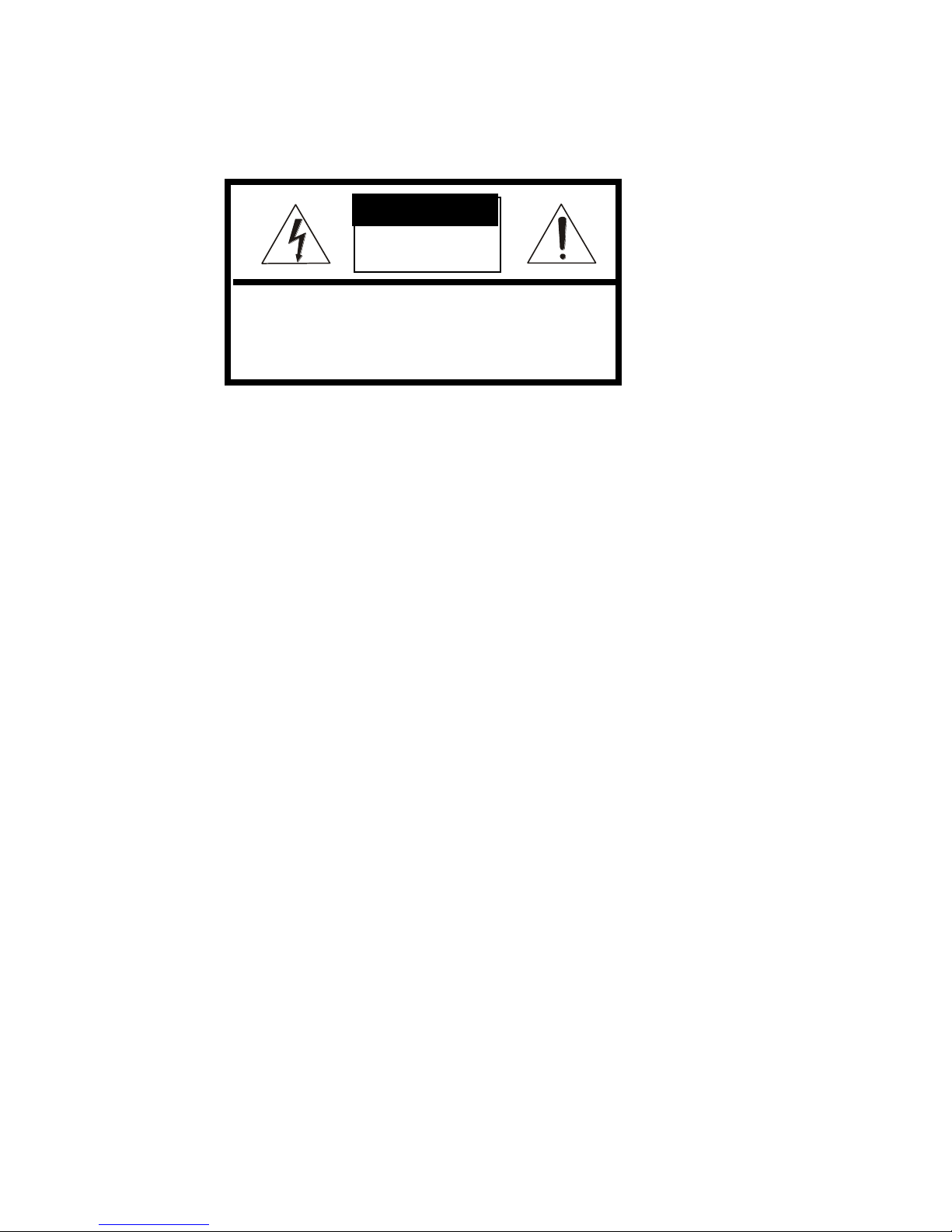
CAUTION
WARNING: TO REDUCE THE RISK OF ELECTRIC SHOCK,
DO NOT REMOVE COVER (OR BACK).
NO USER-SERVICABLE PARTS INSIDE.
REFER SERVICING TO QUALIFIED SERVICE PERSONNEL.
RISK OF ELECTRIC SHOCK
DO NOT OPEN
CAUTION

VK2-1080XPTZ User Manual V1.0
5
IMPORTANT SAFETY INSTRUCTIONS
Read these instructions.
1. Keep these instructions.
2. Heed all warnings.
3. Follow all instructions.
4. Do not use this apparatus near water.
5. Clean only with dry cloth.
6. Do not block any ventilation openings. Install in accordance with the manufacturer’s
instructions.
7. Do not install near any heat sources such as radiators, heat registers, stoves, or
other apparatus (including amplifiers) that produce heat.
8. Do not defeat the safety purpose of the polarized or grounding-type plug. A
polarized plug has two blades with one wider than the other. A grounding type plug
has two blades and a third grounding prong. The wide blade or the third prong is
provided for your safety. If the provided plug does not fit into your outlet, consult an
electrician for replacement of the obsolete outlet.
9. Protect the power cord from being walked on or pinched particularly at plugs,
convenience receptacles, and the point where they exit from the apparatus.
10. Only use attachments/accessories specified by the manufacturer.
11. Use only with the cart, stand, tripod, bracket, or table specified
by the manufacturer, or sold with the apparatus. When a cart is
used, use caution when moving the cart/apparatus combination
to avoid injury from tip-over.
12. Unplug this apparatus during lightning storms or when unused
for long periods of time.
13. Refer all servicing to qualified service personnel. Servicing is
required when the apparatus has been damaged in any way, such as power-supply
cord or plug is damaged, liquid has been spilled or objects have fallen into the
apparatus, the apparatus has been exposed to rain or moisture, does not operate
normally, or has been dropped.
14. CAUTION – THESE SERVICING INSTRUCTIONS ARE FOR USE BY QUALIFIED
SERVICE PERSONNEL ONLY. TO REDUCE THE RISK OF ELECTRIC SHOCK
DO NOT PERFORM ANY SERVICING OTHER THAN THAT CONTAINED IN THE
OPERATING INSTRUCTIONS UNLESS YOU ARE QUALIFIED TO DO SO.
15. Use satisfy clause 2.5 of IEC60950-1/UL60950-1 or Certified/Listed Class 2
power source only.
16. ITE is to be connected only to PoE networks without routing to the outside plant.

VK2-1080XPTZ User Manual V1.0
6
TABLE OF CONTENTS
1. DESCRIPTION ............................................................................................................... 8
1.1 Key Features ....................................................................................................................... 9
2. INSTALLATION............................................................................................................ 10
Before Installation .................................................................................................................. 10
2.1 Base Installation ............................................................................................................... 10
2.2 Basic Configuration of Dome Camera System ............................................................... 13
2.3 Setting Network Dome Camera Termination .................................................................. 14
Reset .................................................................................................................................... 14
Setting the RS485 Dome Camera Address (ID) ................................................................. 15
Setting the RS485 Dome Protocol ..................................................................................... 15
Connections ........................................................................................................................ 15
.................................................................................................... Error! Bookmark not defined.
2.4 Setting the cameras IP address ....................................................................................... 16
2.5 Network Connection & IP assignment ............................................................................ 18
3. Operation ..................................................................................................................... 19
3.1 Access from a browser .................................................................................................... 19
3.2 Access from the internet .................................................................................................. 20
3.3 Setting the admin password over a secure connection ................................................ 20
3.4 Live View Page ................................................................................................................. 21
3.5 VK2-1080XPTZ Setup ...................................................................................................... 23
3.5.1 Basic Configuration ................................................................................................... 23
1) Users ............................................................................................................................ 24
2) Network ........................................................................................................................ 25
3) Video & Image ............................................................................................................. 26
4) Audio ............................................................................................................................ 28
5) Date & Time ................................................................................................................. 29
3.5.2 Live View .................................................................................................................... 30
3.5.3 Video & Image ............................................................................................................ 30
1) Basic ............................................................................................................................ 30
2) Image............................................................................................................................ 31
3) Auto Exposure ............................................................................................................. 32
4) Day & Night ................................ .................................................................................. 33
5) Auto Focus .................................................................................................................. 34
6) DIS ................................................................................................................................ 35
7) Webcasting .................................................................................................................. 35

VK2-1080XPTZ User Manual V1.0
7
3.5.4 Audio .......................................................................................................................... 36
3.5.5 Event ........................................................................................................................... 36
1) Event In ........................................................................................................................ 36
2) Event Out ................................................................ ..................................................... 40
3) Event Map .................................................................................................................... 46
3.5.6 Dome Configuration ................................................................................................... 48
1) Preset ........................................................................................................................... 48
2) Tour .............................................................................................................................. 49
3) Motor Setup ................................................................................................................. 50
4) RS485 ........................................................................................................................... 51
5) View Angle ................................................................................................................... 51
6) System Menu ............................................................................................................... 52
7) Privacy Zone ................................................................................................................ 53
3.5.7 System ........................................................................................................................ 54
1) Information .................................................................................................................. 54
2) Security ........................................................................................................................ 54
3) Date & Time ................................................................................................................. 56
4) Network ........................................................................................................................ 58
5) Language ................................................................ ..................................................... 66
6) Maintenance ................................................................................................................ 67
7) Support ........................................................................................................................ 68
3.6 Help ................................................................................................................................... 70
3.7 Resetting to the factory default settings......................................................................... 70
4. Appendix ..................................................................................................................... 71
4.1 Troubleshooting ............................................................................................................... 71
4.2 Alarm Connection ............................................................................................................. 72
4.3 Preventive Maintenance ................................................................................................... 72
4.4 Product Specification ....................................................................................................... 73
4.5 System Requirement for Web Browser ........................................................................... 75
4.6 General Performance Considerations ................................................................ ............. 75

VK2-1080XPTZ User Manual V1.0
8
1. DESCRIPTION
-------------------------------------------------------------------------------------------------------------------------------------
This manual applies to the VK2-1080XPTZ fully functional PTZ network camera.
These cameras are fully featured for security surveillance and remote monitoring needs. They are
based on the DSP compression chip, allowing real-time, full frame rate Motion JPEG and H.264 (or
MPEG-4) video streams.
Components
Quantity
Description
1
Camera
1
Bubble Ring
3
Assembly Screws for Attaching Network Dome Camera
1
Installation CD
3
Rawl plugs
NOTE
Adapter for DC12V / AC24V are not supplied.

VK2-1080XPTZ User Manual V1.0
9
1.1 Key Features
HDTV Video Quality
The VK2-1080XPTZ is capable of providing the outstanding image quality with HDTV performance
and profiles (High, Main, and Baseline) in H.264 compression.
Triple Streaming
Each stream can be programmed independently and transmitted using different configurations.
Codecs
The camera supports thre standard compressions formats H.264, MJPEG and MPEG4
Built-in optical Zoom
Support maximum 30x optical
Intelligent Video Motion Detection
The HDS Series offers intelligent & sophisticated video motion detection for each multiple streams.
Triple Power (Power over Ethernet, DC12V, AC24V)
This camera supports Power over Ethernet (PoE), which supplies power to the camera through the
network. If the network has no PoE, connect a DC12V or AC24V power connector.
Day and Night
The HDS Series provide clear monitoring images even in low light conditions using IR-cut filter.
Voice Alert Linked to Alarm Detection
The HDS Series can play the audio file stored in the camera in synchronization with alarm
detection by the sensor input or the motion detection function.
Network Flow Control
The HDS Series provides a flow control function which enhances network efficiency by significantly
restricting user video streams with designating the maximum bandwidth.
ONVIF Certificate
The HDS Series network camera complies with the ONVIF certificate. ONVIF (Open Network
Video Interface Forum) is an open industry forum for the development of a global standard for the
interface of network video product.
VK2-1080XPTZ User Manual V1.0
10
2. INSTALLATION
-------------------------------------------------------------------------------------------------------------------------------------
Before Installation
Before installing the camera, thoroughly familiarize yourself with the information in this section of
the manual.
- Recommend connecting the camera to a network that uses a DHCP (Dynamic Host Configuration
Protocol) server to address devices.
- To ensure secure access to the IP camera, place the camera behind a firewall when it is
connected to a network.
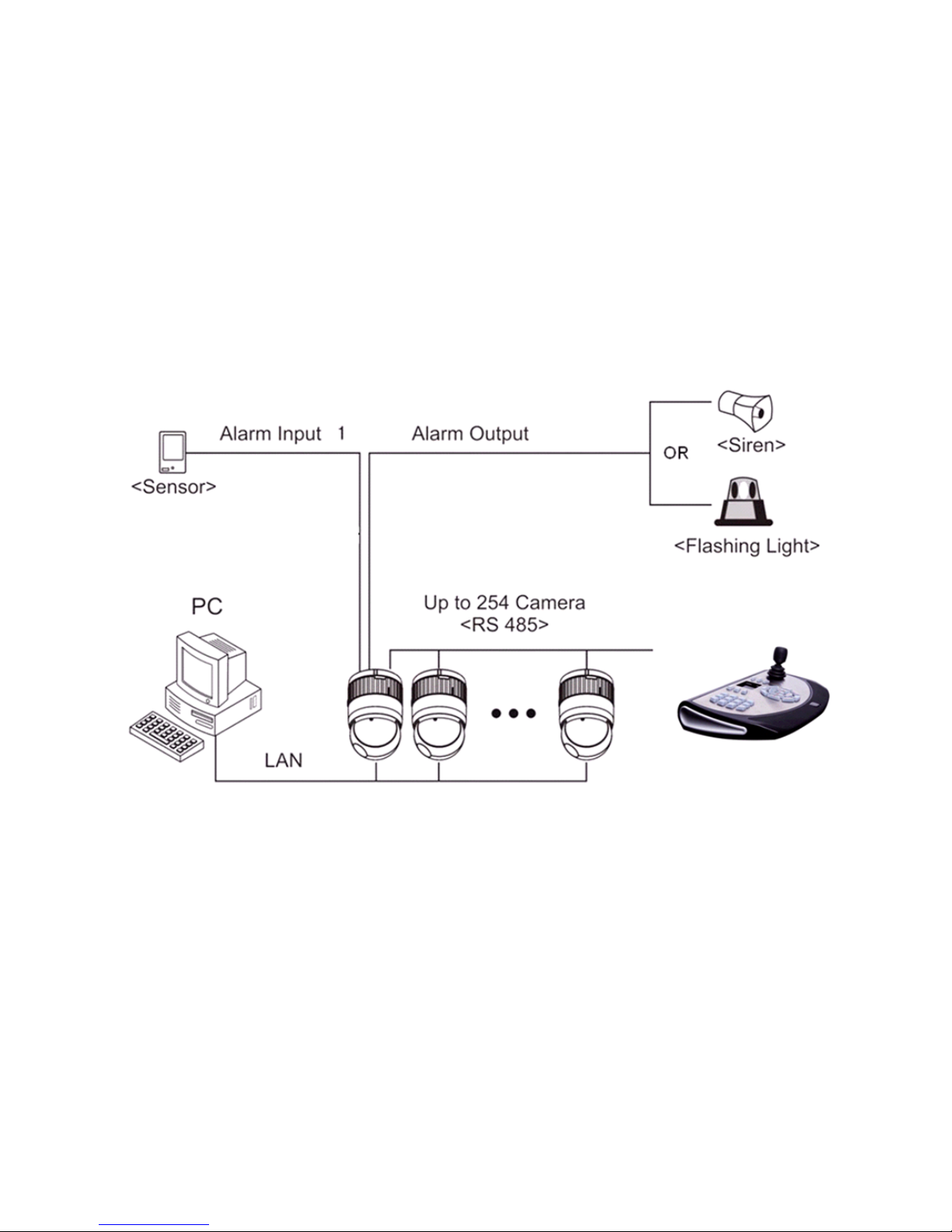
2.1 Base Installation
Typical System Configuration
VK2-1080XPTZ User Manual V1.0
11
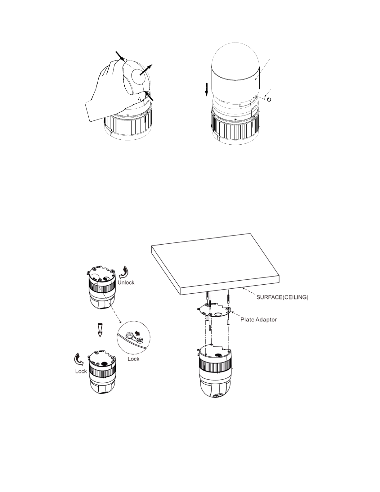
Assemble bubble ring ass’y(Optional)
NOTES
It is recommended that the camera window is removed when you use bubble ring assembly is used; this will improve the
picture quality.
The Network Dome Camera is for use in surface mounting applications and the mounting surface
should be capable of supporting loads up to 10lb (4.5kg).
The Network Dome Camera’s base should be attached to a structural object, such as hard wood,
wall stud or ceiling rafter that supports the weight of the Network Dome Camera.
Installation
push
remove window
assemble bubble ring ass'y
push
remove camera window
bubble ring ass'y
screw
VK2-1080XPTZ User Manual V1.0
12
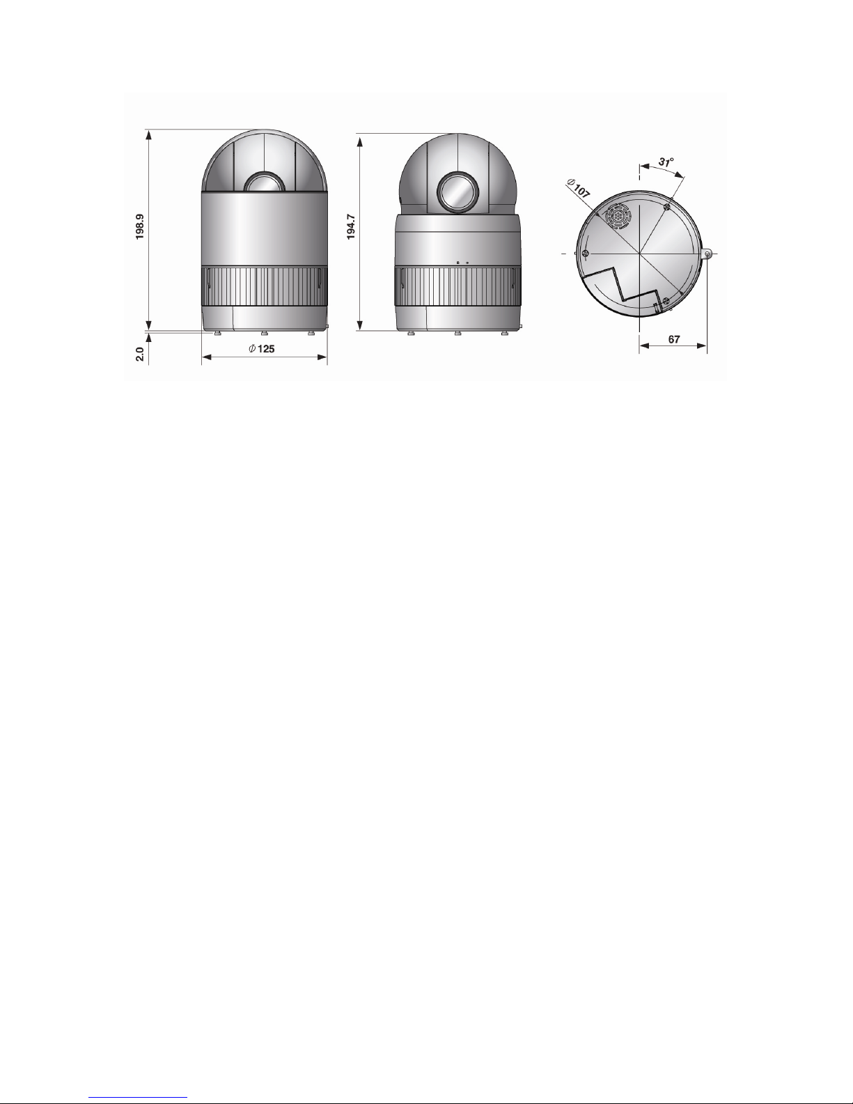
Dimensions
VK2-1080XPTZ User Manual V1.0
13
2.2 Basic Configuration of Dome Camera System
Basic installation diagram
The Network Dome Camera must be installed by qualified service personnel in accordance with all
local and federal electrical and building codes. The system should be installed according to Figures
5 through 8.
VK2-1080XPTZ User Manual V1.0
14
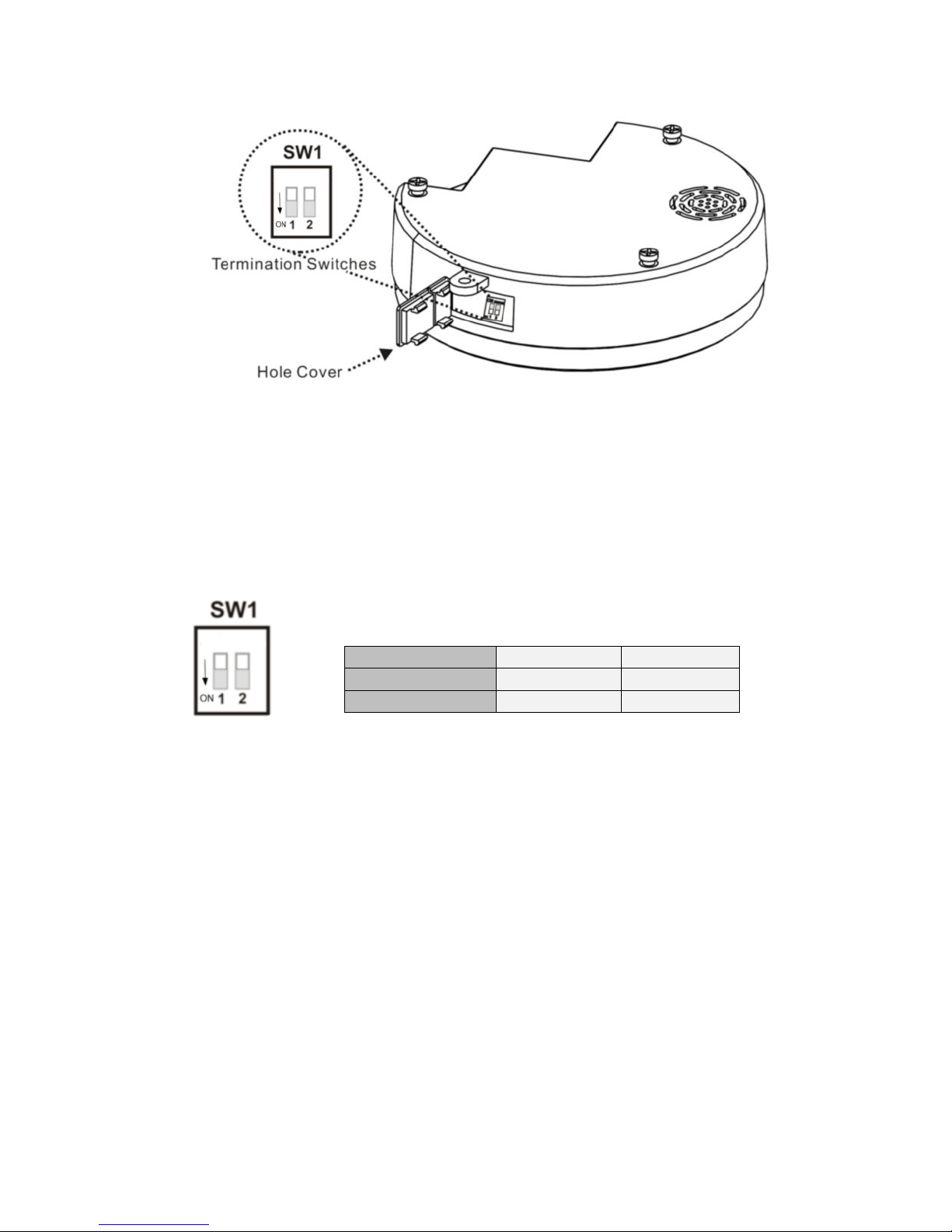
Layout of Switches
2.3 Setting Network Dome Camera Termination
The device which is connected at end of line, whether it is a Network Dome Camera or keyboard
controller, must have the cable for communication terminated by setting the appropriate DIP switch.
Without proper termination, there is potential for control signal errors. Total length of the cable for
communication should not exceed 1.2km (4000ft).
Figure 1. Setting
Network Dome Camera Termination
Reset
To restore the camera’s factory default settings. Turn on dip switch 2 for 15s and then turn off.
Please take steps as follows:
1. Power off
2. Move switch 2 to On
3. Power up the camera
4. wait for 15 seconds and move SW2 to off
SW1
1
2
Terminated
ON
RESET
Not terminated
OFF
OFF

VK2-1080XPTZ User Manual V1.0
15
Setting the RS485 Dome Camera Address (ID)
Each Dome Camera must have a unique address (ID). When installing multiple Network Dome
Cameras using a multiplexer, it is suggested that the Network Dome Camera address match the
multiplexer port number.
If you want to set the address more than 999, you should contact the service provider.
Refer to ‘Dome Configuration - RS485’ section for detailed information.
Setting the RS485 Dome Protocol
Refer to ‘Dome Configuration - RS485’ section for detailed information.
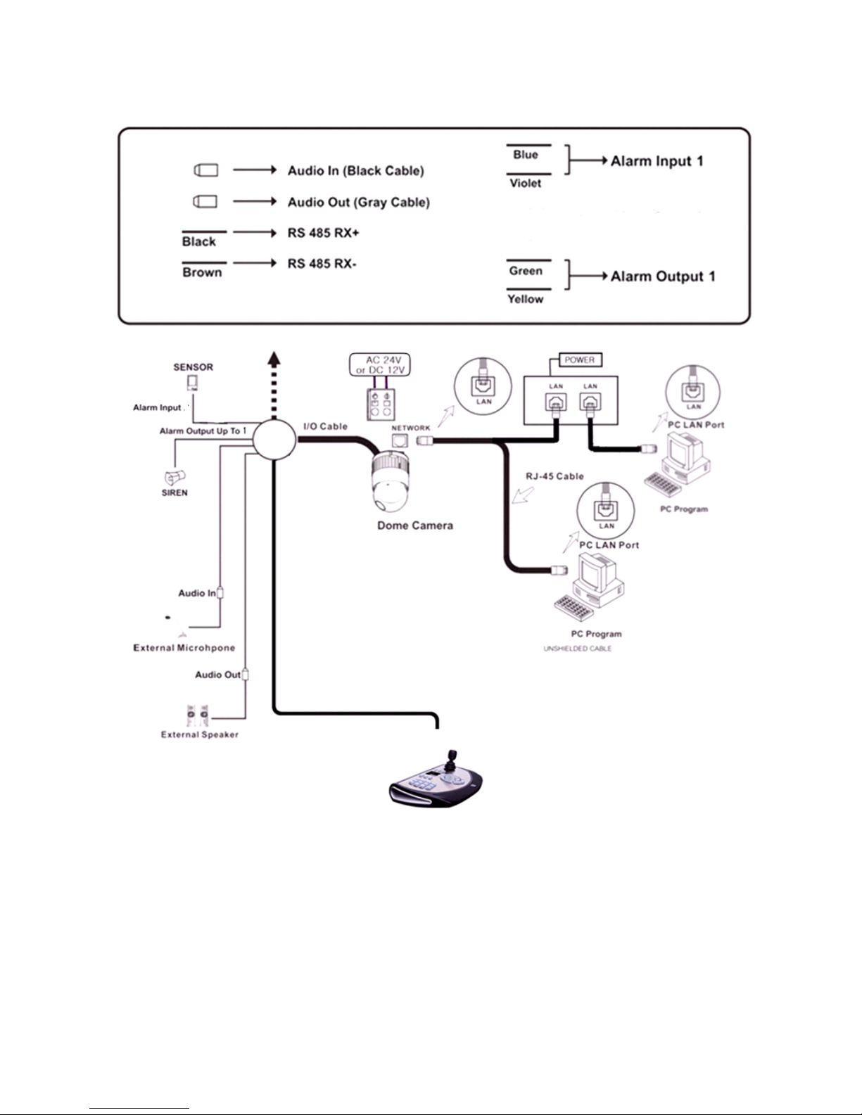
Connections
Connecting to the RS485
The Network Dome Camera can be controlled remotely by an external device or control system,
such as a control keyboard, using RS485 half-duplex serial communications signals. Connect
Marked Rx+, Rx- to Tx+ and Tx- of the RS485 control system.
Connecting Alarms
AL1 (Alarm In)
You can use external devices to signal the Network Dome Camera to react on events. Mechanical
or electrical switches can be wired to the AL (Alarm In) and GND (Ground) connectors.
GND(Ground)
Connect the ground side of the Alarm input and/or alarm output to the GND connector.
NC (NO) (Normal Close or Normal Open: Alarm Out)
The Network Dome Camera can activate external devices such as buzzers or lights. Connect the
device to the NC (NO) (Alarm Out) and COM (Common) connectors.
VK2-1080XPTZ User Manual V1.0
16
Connecting the Network
The Network Dome Camera supports the operation through the network. Therefore, it is necessary
to connect a standard RJ-45 cable to it. Generally a cross cable is used for directly connection to
PC, while a direct cable is used for connection to a hub.
Connecting the Power
Connect power of 12VDC or 24VAC 1.5A for the camera.When using a 12VDC adapter,
connect the positive (+) pole to the ‘+’ position and
the negative (-) pole to the ‘-’ position.
Use satisfy clause 2.5 of IEC60950-1/UL60950-1 or Certified/Listed Class 2 power source
only.
- Be careful not to reverse the polarity when you connect the power cable.
- You can also use a router featuring PoE (Power over Ethernet) to supply power to the
camera.
- If PoE and 12VDC are both applied, this camera will get supplied with power from PoE.
- 24VAC is recommended to use for the camera power for stable operation with heater kit.
If using PoE, the heater will not operate at all.
2.4 Setting the cameras IP address
IP Assignment
When a camera is first connected to the network it has no IP address. So, it is necessary to
allocate an IP address to the device with the “Smart Manager” utility on the CD.
1. Connect the Network Camera / device to the network and power up.
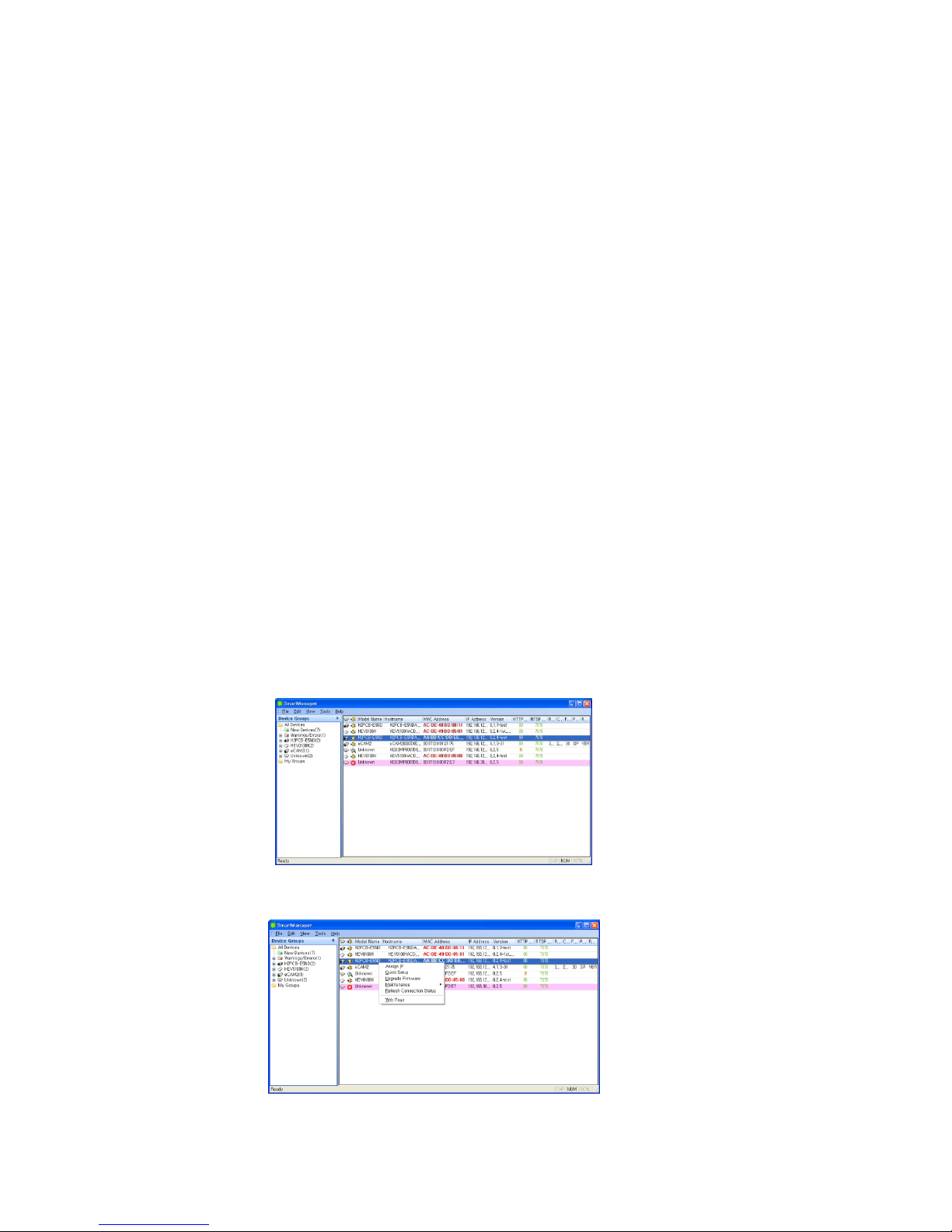
2. Start Smart Manager utility, the main window will be displayed, after a short while any network
devices connected to the network will be displayed in the list.
3. Select the camera on the list and click right button of the mouse. You will see the following
menu as below:
VK2-1080XPTZ User Manual V1.0
17
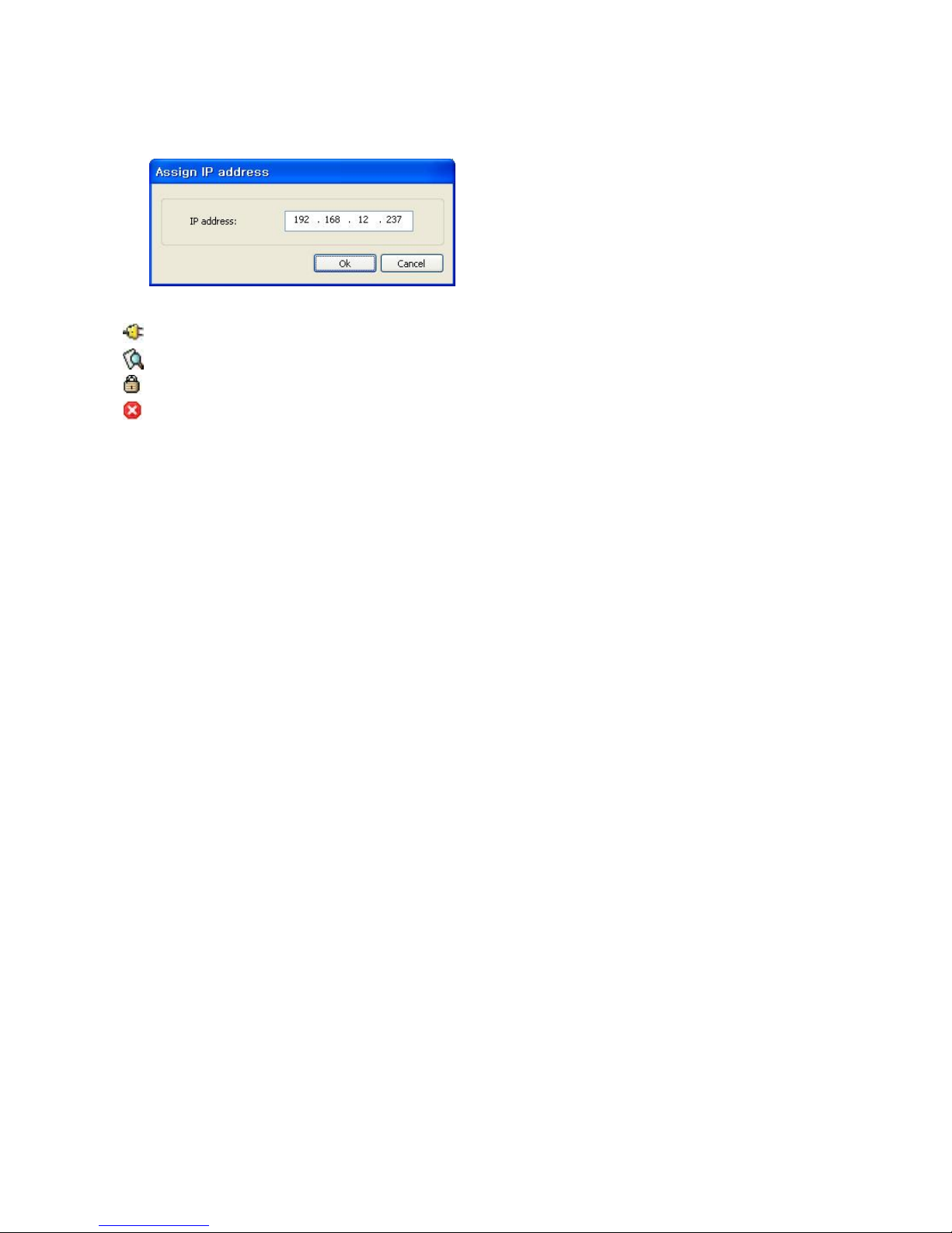
4. Select Assign IP. You cam see an Assign IP window.
5. Enter the required IP address.
The description of each field for the connection status follows.
: Available for connection to the camera
: Loading settings information of video after connecting the camera.
: Connectable to the camera but fixed security settings (password)
: Unavailable for connection to the camera (PC can not access relevant IP Address)
Note: For more information, refer to the Smart Manger User’s Manual.
VK2-1080XPTZ User Manual V1.0
18
2.5 Network Connection & IP assignment
The camera supports the operation through the network. When a camera is first connected to the
network, it is necessary to allocate an IP address to the device with the “SmartManager” utility on
the CD. (Default IP 192.168.30.220)
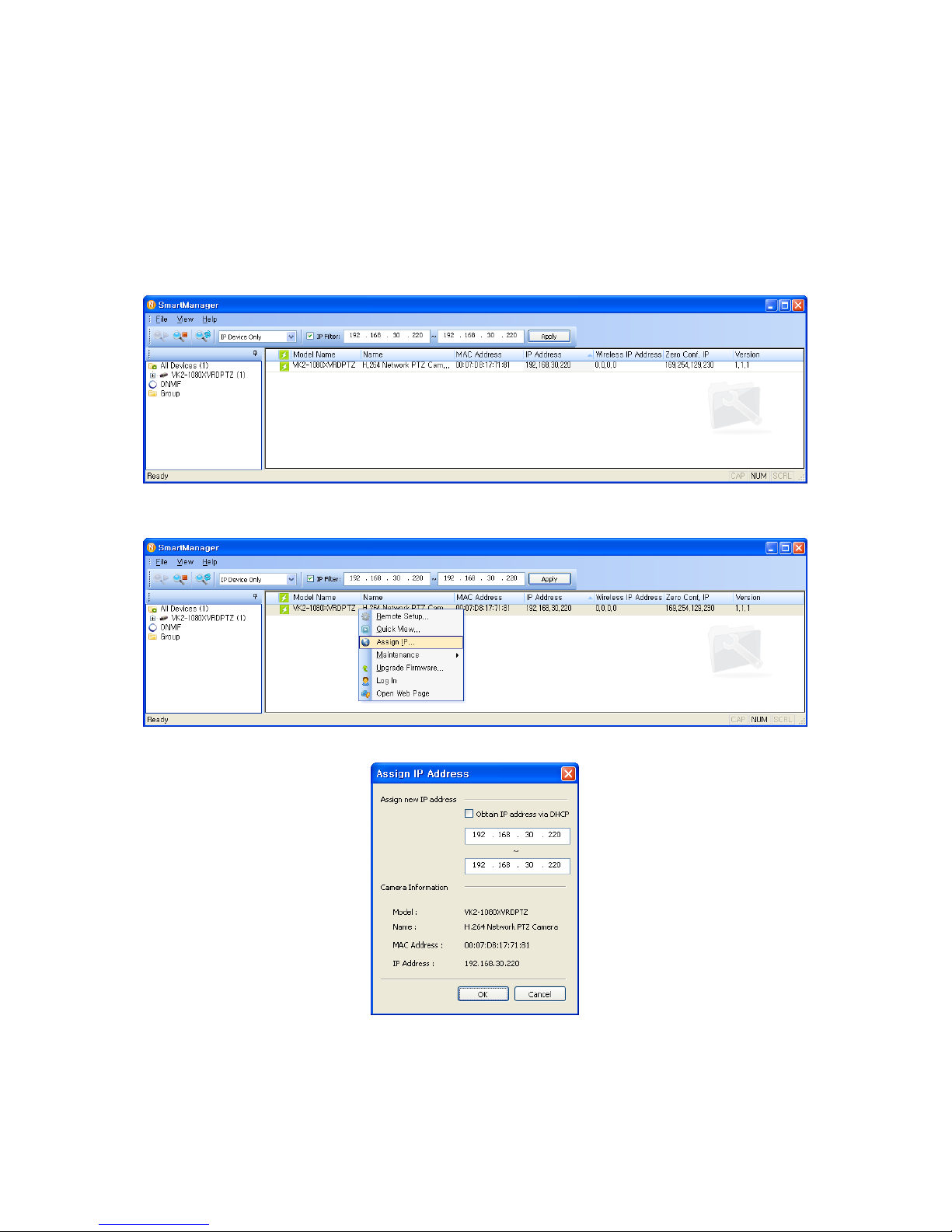
1) Connect the network camera/device to the network and power up.
2) Start SmartManager utility (Start > All programs > SmartManager > SmartManager). The main
window will display, and after a short while any network devices connected to the network will
be displayed in the list.
3) Select the camera on the list and click right button of the mouse. You can see the pop-up
menu as below.
4) Select Assign IP Address. The Assign IP window will display. Enter the required IP address.
NOTE: More if multiple cameras are selected then a range of Ip addresses can be configured.
For more information, refer to the SmartManager User’s Manual.
VK2-1080XPTZ User Manual V1.0
19
3. Operation
The VK2-1080XPTZ can be used with Windows® operating system and browsers. The
recommended browsers are Internet Explorer®, Safari®, Firefox®, Opera™ and Google®
Chrome® with Windows.
NOTE: To view streaming video in Microsoft Internet Explorer, set your browser to allow ActiveX
controls.
3.1 Access from a browser
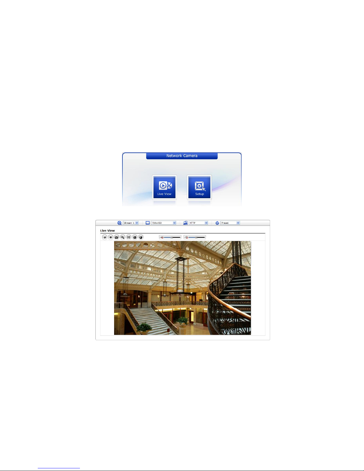
1) Start a browser (Internet Explorer).
2) Enter the IP address or host name of the in the Location/Address field of your browser.
3) You can see a starting page. Click Live View or Setup to enter web page.
4) The network camera’s Live View page appears in your browser.
VK2-1080XPTZ User Manual V1.0
20
3.2 Access from the internet
Once connected, the VK2-1080XPTZ is accessible on your local network (LAN). To access the
VK2-1080XPTZ from the Internet you must configure your broadband router to allow incoming
data traffic to the network camera. To do this, enable the NAT traversal feature, which will attempt
to automatically configure the router to allow access to the network camera. This is enabled from
Setup > System > Network > NAT. For more information, please see “3.5.7 System > Network >
NAT” of User's Manual.
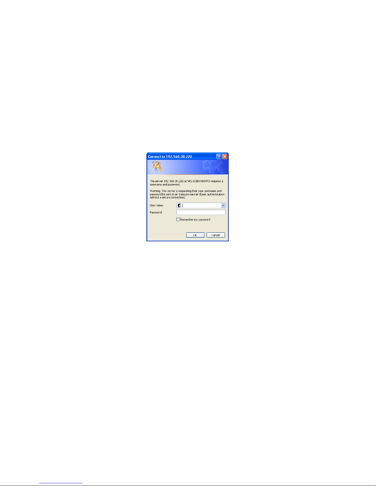
3.3 Setting the admin password over a secure connection
To gain access to the product, the password for the default administrator user must be set. This is
done in the “Admin Password” dialog, which is displayed when the VK2-1080XPTZ is accessed for
the setup at the first time. Enter your admin name and password, set by the administrator.
NOTE: The default administrator user name and password is “admin”. If the password is lost, the
must be reset to the factory default settings. Please see “Resetting to the factory default
settings”.
To prevent network eavesdropping when setting the admin password, this can be done via an
encrypted HTTPS connection, which requires an HTTPS certificate (see NOTE below).
To set the password via a standard HTTP connection, enter it directly in the first dialog shown
below. To set the password via an encrypted HTTPS connection, please see “3.5.7 System >
Security > HTTPS” of User's Manual.
NOTE: HTTPS (Hypertext Transfer Protocol over SSL) is a protocol used to encrypt the traffic
between web browsers and servers. The HTTPS certificate controls the encrypted
exchange of information.
VK2-1080XPTZ User Manual V1.0
21
3.4 Live View Page
The Live View page comes in several screen modes: 1920x1080, 1280x1024, 1280x720, 704x576,
704x480, 640x480 and 320x240. Users are allowed to select the most suitable one out of those
modes. Adjust the mode in accordance with your PC specifications and monitoring purposes.
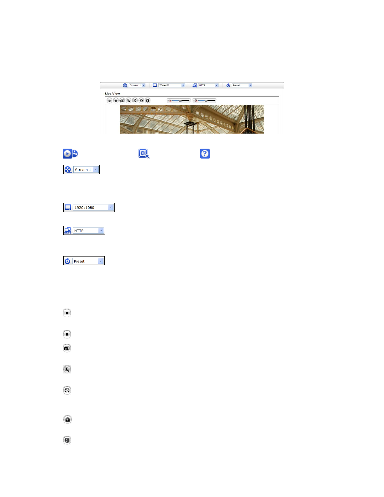
1) General controls
Live View Page Setup Page Help Page
The video drop-down list allows you to select a customized or pre-programmed
video stream on the Live View page. Stream profiles are configured under
Setup > Basic Configuration > Video & Image. For more information, please
see “3.5.1 Basic Configuration > Video & Image” of User’s Manual.
The resolution drop-down list allows you to select the most suitable one
out of video resolutions to be displayed on Live View page.
The protocol drop-down list allows you to select which combination of
protocols and methods to use depending on your viewing requirements, and
on the properties of your network.
The preset drop-down list allows you to select the preset number for the PTZ
camera being used. This icon is inactivated if the PTZ settings are not set.
2) Control toolbar
The live viewer toolbar is available in the web browser page only. It displays the following
buttons:
The Stop button stops the video stream being played. Pressing the key again toggles the
start and stop. The Start button connects to the or starts playing a video stream.
The Pause button pauses the video stream being played.
The Snapshot button takes a snapshot of the current image. The location where the
image is saved can be specified.
The Digital Zoom button activates a zoom-in or zoom-out function for video image on the
live screen.
The Full Screen button causes the video image to fill the entire screen area. No other
windows will be visible. Press the 'Esc' button on the computer keyboard to cancel full
screen view.
The Manual Trigger button activates a pop-up window to manually start or stop the
event.
The PTZ button activates a pop-up window for Pan, Tilt and Zoom control.

VK2-1080XPTZ User Manual V1.0
22
Use this scale to control the volume of the speakers.
Use this scale to control the volume of the microphone.
Use this scale to control the volume of the speakers and microphones.
3) Video Streams
The VK2-1080XPTZ provides several images and video stream formats. Your requirements
and the properties of your network will determine the type you use.
The Live View page in the VK2-1080XPTZ provides access to H.264 and Motion JPEG video
streams, and to the list of available video streams. Other applications and clients can also
access these video streams/images directly, without going via the Live View page.
VK2-1080XPTZ User Manual V1.0
23
3.5 VK2-1080XPTZ Setup
This section describes how to configure the network camera, and is intended for product.
Administrators, who have unrestricted access to all the Setup tools; and Operators, who have
access to the settings for Basic Configuration, Live View, Video & Image, Audio, Event, Dome
Configuration, System
You can configure the VK2-1080XPTZ by clicking Setup in the top right-hand corner of the Live
View page. Click on this page to access the online help that explains the setup tools.
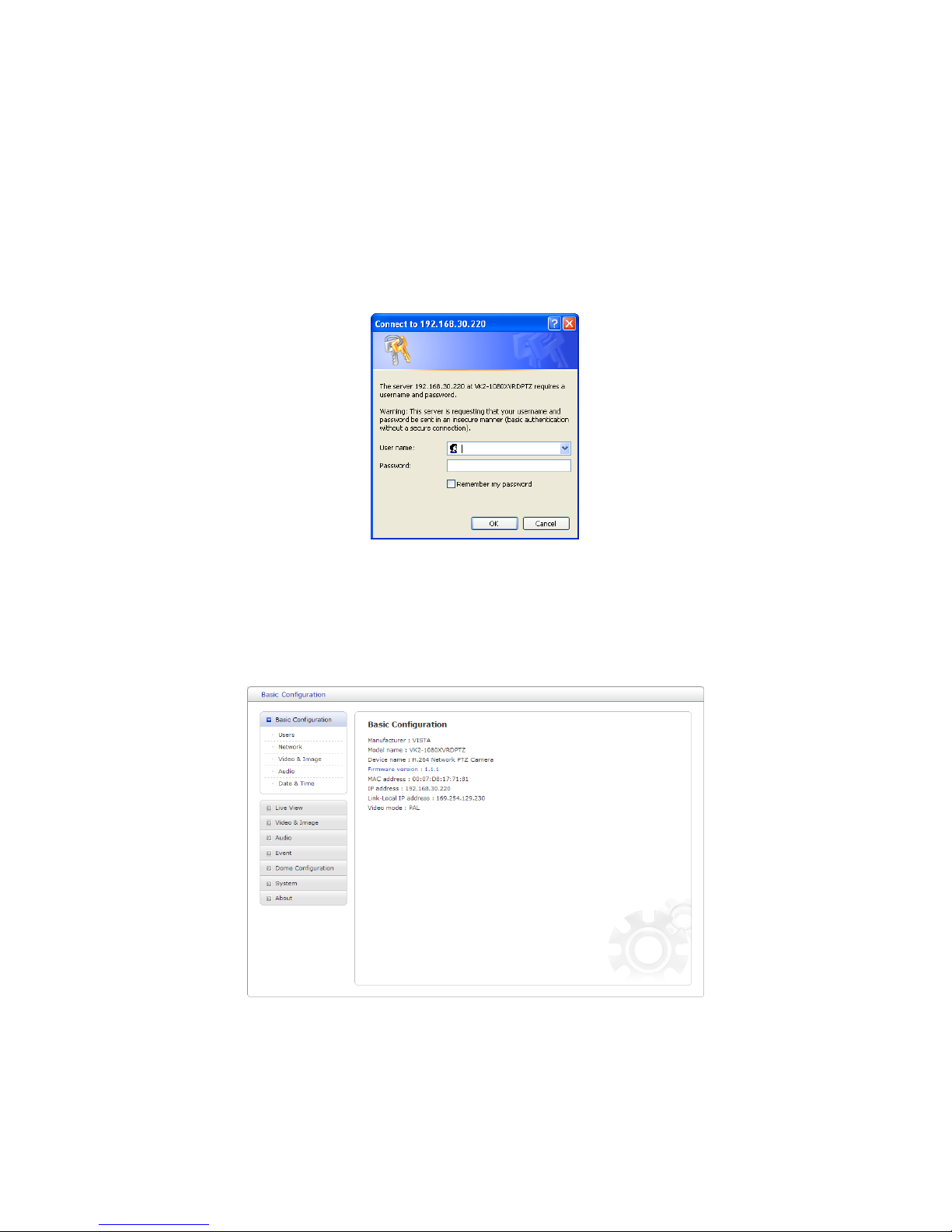
When accessing the VK2-1080XPTZ for the first time, the “Admin Password” dialog appears.
Enter your admin name and password, set by the administrator.
NOTE: If the password is lost, the VK2-1080XPTZ must be reset to the factory default settings.
Please see “Resetting to the Factory Default Settings”.
3.5.1 Basic Configuration
You can see the device information in this information page.
 Loading...