

Vista 10SE, N7227V5 User Manual

9,,
9
6
6
7
7
$
$
6
6
(
(
6HFXULW\6\VWHP
,QVWDOODWLRQDQG6HWXS*XLGH
*
AWAY
NO AC
STAY
CHIME
INSTANT
BAT
ALARM
BYPASS
CHECK
FIRE
NOT READY
OFF AWAY STAY
2
1
MAX TEST BYPASS
INSTANT CODE CHIME
897
READY
0
*
PANIC
ARMED
READY
3
654
#
•
•
•
•
•
•
•
•
•
•
•
•
•
•
•
•
•
•
•
®
N7227V5 10/00

RECOMMENDATIONS FOR PROPER PROTECTION
DINING
KITCHEN
BEDROOM
BEDROOM
BEDROOM
BEDROOM
LIVING ROOM
✪
✪
✪
✪
✪
▲
▲
BEDROOM
BDRM
BDRM
DINING
LIVING ROOM
TV ROOM
KITCHEN
■
■
■
✪
✪
✪
✪✪
✪
▲
✪
✪
✪
BEDROOM
BEDROOM
TO
BR
■
■
■
■
■
LVNG RM
BASEMENT
KTCHN
▲
▲
.
CLOSED
DOOR
GARAGE
▲
Smoke Detectors for Minimum Protection
Smoke Detectors for Additional Protection
Heat-Activated Detectors
The following recommendations for the location of fire and burglary detection devices help provide
proper coverage for the protected premises.
Recommendations for Smoke and Heat Detectors
With regard to the number and placement of smoke/heat detectors, we subscribe to the
recommendations contained in the National Fire Protection Association's (NFPA) Standard #72
noted below.
Early-warning fire dete ctio n is be st achie ve d by th e in stallatio n o f f ire de te ction equ ipm en t in all
rooms and areas of the household as follows: For minimum protection, a smoke detector should
be installed outside of each separate sleeping area, and on each additional floor of a multi-floor
family living unit, includin g basements. The installation of sm oke detectors in kitc hens, attics
(finished or unfinished), or in garages is not normally recommended.
For maximum protection, the NFPA recommends that you install heat or smoke detector s in
the living room, dining room, bedroom(s), kitchen, hallway(s), attic, furnace room, utility and
storage rooms, basements and attached garages.
In addition, we recommend the following:
• Install a smoke detector inside every bedroom where a smoker sleeps.
• Install a smoke detector inside every bedroom where someone sleeps with the door partly or
completely closed. Smoke could be blocked by the closed door. Also, an alarm in the hallway
outside may not wake up the sleeper if the door is closed.
• Install a smoke detector inside bedrooms where electrical appliances (such as portable
heaters, air conditioners, or humidifiers) are used.
• Install a smoke detector at bo th ends of a hallway if the hallway is more than 40 feet (12
meters) long.
• Install smoke detectors in any room where an alarm control is located, or in any room where
alarm control connections to an AC source or phone lines are made. If detectors are not so
located, a fire within the room could prevent the control from reporting a fire or an
intrusion.
THIS CONTROL COMPLIES WITH NFPA REQUIREMENTS FOR
TEMPORAL PULSE SOUNDING FOR FIRE NOTIFICATION APPLIANCES.
Recommendations for Proper Intrusion Protection
For proper intrusion coverage, sensors should be located at every possible point of entry to a home or
commercial premises. This would include any skylights that may be present, and the upper windows
in a multi-level building.
In addition, we recommend th at radio backup be u sed in a security system so that alarm sig nals can
still be sent to the alarm monitorin g station in the event that the teleph one lines are out of order
(alarm signals are normally sent over the phone lines, if connected to an alarm monitoring station).
ii

Table of Contents
••••••••••••••••••••••••••••••••••••••••••••••••••
SECTION 1. Introduction............................................................................................................................1–1
Description........................................................................................................................................................1-1
Features.............................................................................................................................................................1-1
SECTION 2. Installing the Control...........................................................................................................2–1
Mounting the Cabinet ......................................................................................................................................2-1
Installing the Lock (if used) .............................................................................................................................2-1
Mounting the Control's Circuit Board Alone in the Cabinet.........................................................................2-2
Mounting the Control and RF Receiver Circuit Boards Together.................................................................2-2
Standard Phone Line Connections ..................................................................................................................2-3
SECTION 3. Installing Remote Keypads .................................................................................................3–1
Keypads That May Be Used.............................................................................................................................3-1
Wiring to the Keypads......................................................................................................................................3-1
Mounting the Keypads .....................................................................................................................................3-2
Supplementary Power for Additional Keypads ..............................................................................................3-2
Preliminary Checkout Procedure ....................................................................................................................3-3
SECTION 4. Basic Hardwired Zones 1–6 .................................................................................................4–1
Installing the Hardwired Zones.......................................................................................................................4-1
Programming Hardwired Zones ......................................................................................................................4-2
SECTION 5. Wireless Expansion (5800 System) ....................................................................................5–1
About Wireless Expansion ...............................................................................................................................5-1
Installing the 5881/5882 Receiver ...................................................................................................................5-2
Installing the 5800TM Module ........................................................................................................................5-3
About Jam Detection and Reporting ...............................................................................................................5-3
5800 Series Transmitters.................................................................................................................................5-3
Installing 5800 Series Transmitters................................................................................................................5-6
SECTION 6. Relay Output Devices...........................................................................................................6–1
Relay Device Basics..........................................................................................................................................6-1
4204 Relay Modules..........................................................................................................................................6-1
Programming Options ......................................................................................................................................6-2
SECTION 7. 4285 and 4286 VIP Module...................................................................................................7–1
Installing the (Voice Interactive Phone) Module............................................................................................7-1
Programming the Control for Phone Access...................................................................................................7-4
Checking the Operation of the VIP Module....................................................................................................7-4
SECTION 8. External Sounders.................................................................................................................8–1
Compatible Sounders.......................................................................................................................................8–1
Sounder Connections and Power ....................................................................................................................8–2
SECTION 9. Long-Range Radio.................................................................................................................9–1
About Long-Range Radio..................................................................................................................................9-1
Programming for Long-Range Radio...............................................................................................................9-1
Dynamic Signaling Feature .............................................................................................................................9-2
SECTION 10. Audio Alarm Verification (AAV) Unit.............................................................................10–1
About Audio Alarm Verification ....................................................................................................................10-1
iii

SECTION 11. Final Power-Up ....................................................................................................................11–1
Earth Ground Connections ............................................................................................................................11-1
Wiring the AC Transformer...........................................................................................................................11-1
AC Power-Up ..................................................................................................................................................11-2
Calculating the Battery Size Needed ............................................................................................................11-2
Connecting the Backup Battery.....................................................................................................................11-3
SECTION 12. Mechanics of Programming..............................................................................................12–1
About Programming .......................................................................................................................................12-1
Entering the Program Mode ..........................................................................................................................12-1
SECTION 13. Zone Response Type Definitions .....................................................................................13–1
Zone Type Definitions.....................................................................................................................................13-1
SECTION 14. Data Field Descriptions ......................................................................................................14-1
Descriptions of System Data Fields...............................................................................................................14-1
SECTION 15. Zone Programming..............................................................................................................15–1
About Zone Programming .............................................................................................................................15–1
SECTION 16. Output Device Programming............................................................................................16–1
Programming Options Defined .....................................................................................................................16–1
Programming Output Relays........................................................................................................................16–3
SECTION 17. Zone Lists .............................................................................................................................17–1
SECTION 18. Alpha Descriptor Programming ......................................................................................18–1
About Alpha Descriptor Programming..........................................................................................................18-1
Zone Descriptors.............................................................................................................................................18-1
SECTION 19. Remote Programming and Control (Downloading)....................................................1 9–1
SECTION 20. System Communication .....................................................................................................20–1
Panel Communication with Central Station.................................................................................................20-1
Report Code Formats......................................................................................................................................20-1
Table of Contact ID Event Codes...................................................................................................................20-2
SECTION 21. System Operation ................................................................................................................21–1
Security Codes ................................................................................................................................................21-1
Keypad Functions...........................................................................................................................................21-2
Trouble Conditions .........................................................................................................................................21-4
SECTION 22. Testing the System ...............................................................................................................22-1
Test Procedure ................................................................................................................................................22-1
SECTION 23. Specifications & Accessories ............................................................................................23–1
Specifications ..................................................................................................................................................23-1
Accessories (Compatible Devices)..................................................................................................................23-2
APPENDIX A REGULATORY AGENCY STATEMENTS .........................................................................A-1
APPENDIX B Limitations and Warranties................................................................................................B-1
Programming Form .....................................................................................................................................Insert
iv

SECTION 1
Introduction
••••••••••••••••••••••••••••••••••••••••••••••••••
In This Section
Description
♦
••••••••••••••••••••••••••••••••••••••••••••••••••
Features
♦
Description
The VISTA–10SE is a control that supports up to 22 hardwired and wireless zones, plus
remote keypads.
Features
Basic Hardwired Zones
Provides 6 basic hardwired zones having the following characteristics:
•
Zones 1-6 response time is 300–500 milliseconds.
•
Zone 3 programmable fast response time is 10–15 milliseconds.
•
EOLR supervision supporting N.O. or N.C. sensors
•
Zone 5 supports as many 4-wire smoke or heat detectors as can be powered from the
control).
•
Zones 7, 95, and 96 are keypad Panics.
•
Zone 8 is Duress.
•
Zone 9 is Tamper.
Optional Expansion Zones
Wireless Expansion:
•
Supports up to 16 wireless zones.
•
Requires the use of a 5881 (5882 in Canada) type RF receiver (with 5800 Series wireless
transmitters), as shown below.
Receiver Model No. of Zones
5881L (5882L*) Up to 8 5800
5881M (5881M*) Up to 16 5800
5881H (5882H*) Up to 16 5800
*
Used in Canada.
Remote Keypads
Up to 4 of any of the following keypads may be used:
Fixed-Word Keypads:
*
This keypad cannot be used if a 4285/4286 VIP Module is being used.
6127*, 6128, and 6137.
Transmitter Type
Alpha Keypads
When programming from a keypad, a 6139 2-line alpha keypad must be connec ted (but need
not stay in the system).
6139 (2-line alphanumeric display).
6138 (1-line alphanumeric display).
1–1

VISTA-10SE Installation and Setup Guide
Security Codes
• One Master code for entire system (User 2). Installer code is User 1.
• 4 secondary user codes (Users 3–6).
• One duress code (User 8).
Duress Code:
An emergency code that, when used to disarm or arm the system, will send a
silent duress message to the central station
Keypad Panic Keys
•
Up to 3 programmable panic key functions are provided.
•
Designated as Zones 7, 95, 96.
•
Activated by wired and wireless keypads.
•
Reported separately.
Paging Feature
If the paging feature has been programmed for your system, your pager will respond to
certain conditions as they occur in your system, and display code numbers indicating the type
of condition that has occurred.
Quick Arm Feature
“Quick Arm” may be programmed, allowing use of the [#] key in place of the security code for
arming (Quick Arm will not work unless the Master code has been programmed into the
system).
Optional Bell Supervision
This is a hardware-enabled option, achieved by cutting a red jumper on the PC board. If the
“Alarm Output” loop connected to an external sounder is then opened or shorted, a “bell
trouble” message will be displayed at the touchpads, accompanied by a trouble sound. A
trouble report will also be sent to the central station.
.
1-2
Optional RF Jam Detection for 5800 Wireless Systems
If RF jam detection is programmed for a 5800 RF system, the RF receiver will detect a
condition that may impede proper RF reception (i.e., jamming or other RF interference). Such
a condition will produce a message display, and a report will be sent to the central
monitoring station (if trouble reporting is enabled).
Optional Output Relays
•
Up to 4 relays using one 4204 Relay Module.
•
Actions programmable to respond to zone activity or manual keypad ent ries.
Optional VIP Module
•
Supports the ADEMCO 4285/4286 VIP Module.
•
Provides access to t he system via on-premises or off-premises phones for arming,
disarming, etc., plus control of relay outputs.
Optional Long-Range Radio
Allows all messages that have been programmed to go to the primary telephone number to be
reported additionally to a 7720 PLUS or 7820 radio.

Alarm Output
•
Provides a 12VDC, 2 AMP output that can drive the compatible sounders listed in the
EXTERNAL SOUNDERS section (assumes a fully charged battery is connected).
•
Steady output for burglary/panic, or temporal pulse sounding output for fire notification,
as required by UL.
•
Uses current-limiting circuitry for protection.
Auxiliary Power Output
•
Provides 12VDC, 500mA maximum. Uses current limiting circuitry for protection.
•
This output interrupts for smoke detector reset if 4-wire smoke detectors are used.
Programming
•
Programmed options are stored in electrically erasable, nonvolatile EEPROM memory
(information can be reprogrammed at any time and will not be lost in the event of a power
loss).
•
The system can be uploaded, downloaded, or controlled via an IBM-compatible computer,
using ADEMCO's Compass Windows downloading software, and a modem specified by
ADEMCO.
Keypad programming consists of:
•
Data field programming.
•
Interactive (menu) mode programming.
Section 1 - Introduction
For programming from a keypad, a 6139 2-line alpha key pad must be c onnected (but need not
stay in the system).
Communication Formats Supported
•
ADEMCO Low Speed (Standard or Expanded)
•
Sescoa/Radionics (Standard or Expanded)
•
ADEMCO Express
•
ADEMCO Contact ID
Zone Descriptors
You can assign alpha descriptors to all zones (useful only when using alpha keypads and/or
the 4285/4286 VIP Module).
AC Power Supply
Uses No. 1321, 120VAC plug-in transformer with 16.5VAC 25VA output (1321CN in
Canada).
Backup Battery
Rechargeable (Sealed Lead Acid) 12VDC, 4AH minimum.
1-3

VISTA-10SE Installation and Setup Guide
1-4
SECTION 2
Installing the Control
••••••••••••••••••••••••••••••••••••••••••••••••••
In This Section
Mounting the Control and RF Receiver Circuit
Mounting the Cabinet
♦
Installing the Lock
♦
Mounting the Control's Circuit Board Alone in
♦
the Cabinet
••••••••••••••••••••••••••••••••••••••••••••••••••
Mounting the Cabinet
Mount the control cabinet to a sturdy wall using fasteners or anchors (not supplied), in a
clean, dry area that is not readily accessible to the general public. Four mounting holes are
provided at the back of the cabinet for this purpose.
If an RF receiver is being used and you intend to mount its PC board within the cabinet, note
the following:
•
Do not mount the cabinet on or near metal objects. This will decrease RF range and/or
block RF transmissions from wireless transmitters.
♦
Board in the Cabinet
Standard Phone Line Connections
♦
•
Do not locate the cabinet in an area of high RF interference (revealed by frequent or pro-
longed lighting of the LED in the receiver after it is operational). Random flicker is OK.
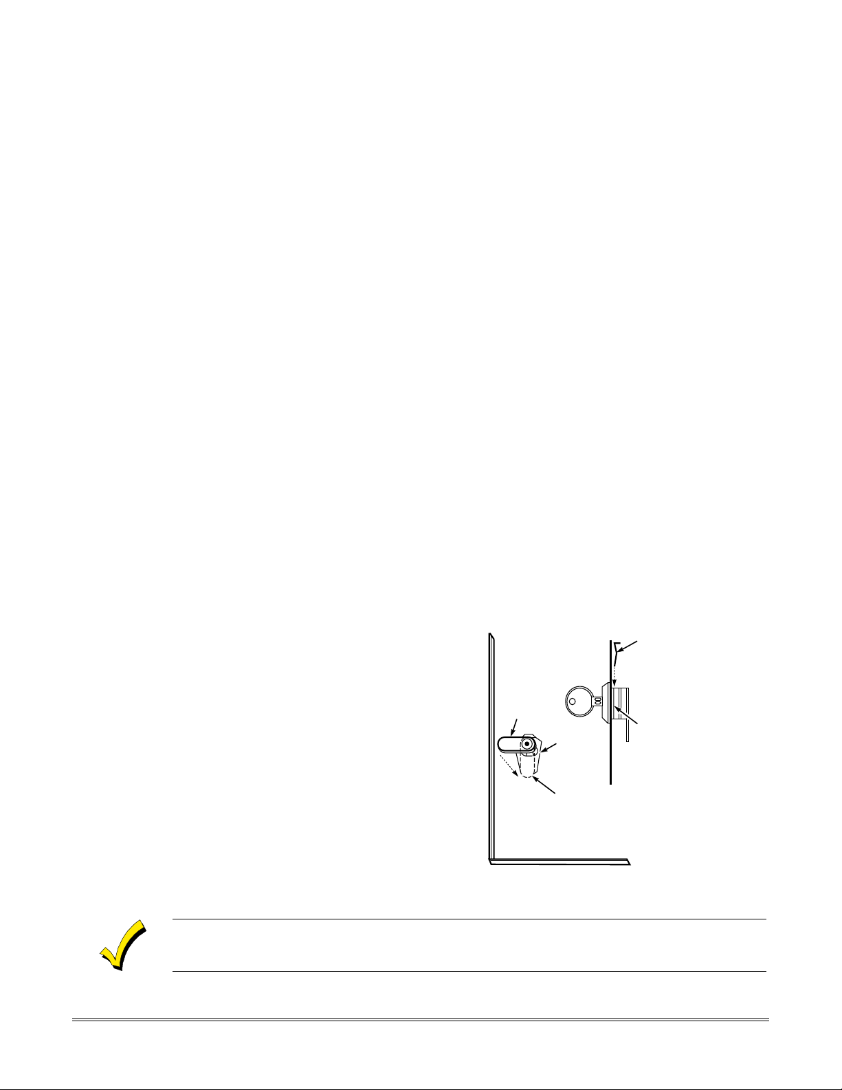
Installing the Lock
Use an ADEMCO No. N6277 Cam Lock and No. N6277–1 Push-On Clip (Retainer Clip).
NOTE:The cabinet can be closed and secured
1. Remove the cabinet door.
removable for servicing and is easily
re-installed.
2. Remove the lock knockout from the
control cabinet door. Insert the key
into the lock. Position the loc k in the
hole, making certain that the latch
will make contact with the latch
bracket when the door is closed.
3. Hold the lo ck steady, and insert the
retainer clip into the retainer slots.
Position the clip as illustrated in
order to permit easy removal.
edge.
It is easily
without
a lock by using 2 screws in the cover's
LOCKED
RETAINER
CLIP
UNLOCKED
CABINET DOOR BOTTOM
Figure 1. Installing the Lock
RETAINER CLIP
(NOTE POSITION)
RETAINER
SLOTS
V10SE-002-V0
Before installing the cabinet's contents, remove the metal c abinet knockouts required for wiring
entry. Do not attempt to remove the knockouts after the circuit board has been installed.
2–1
VISTA-10SE Installation and Setup Guide
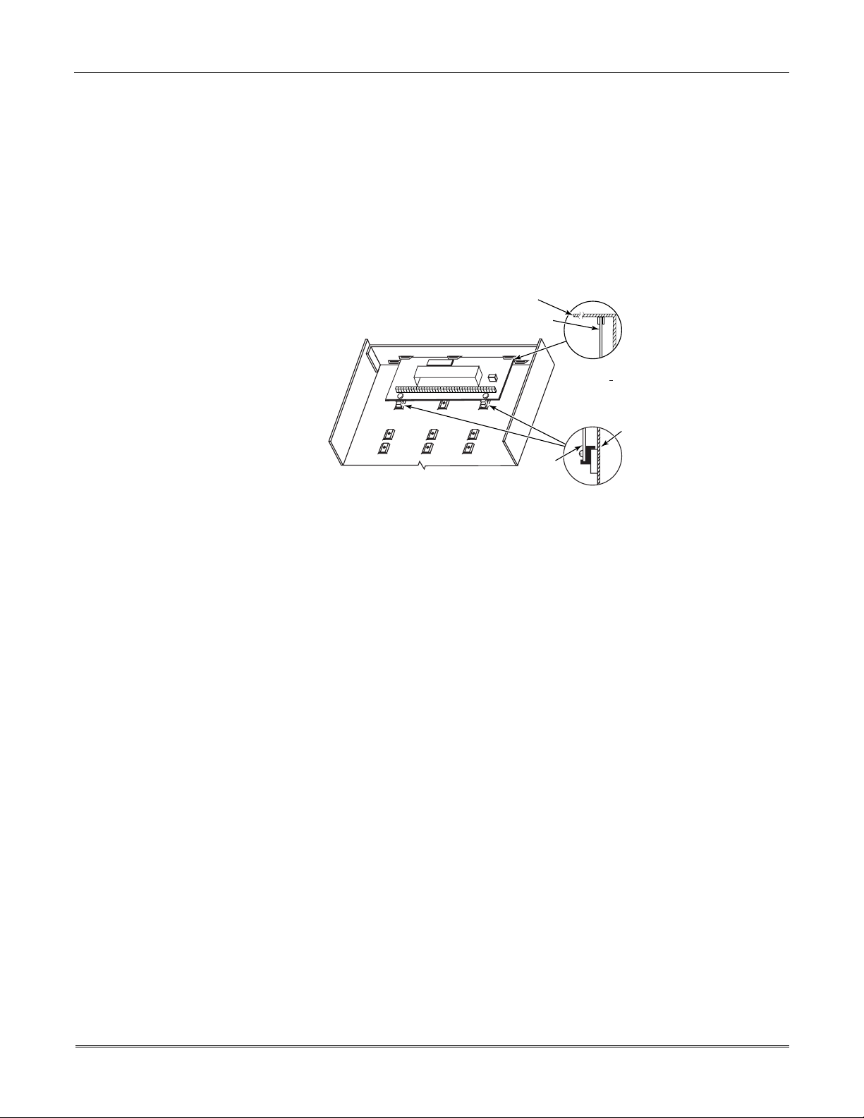
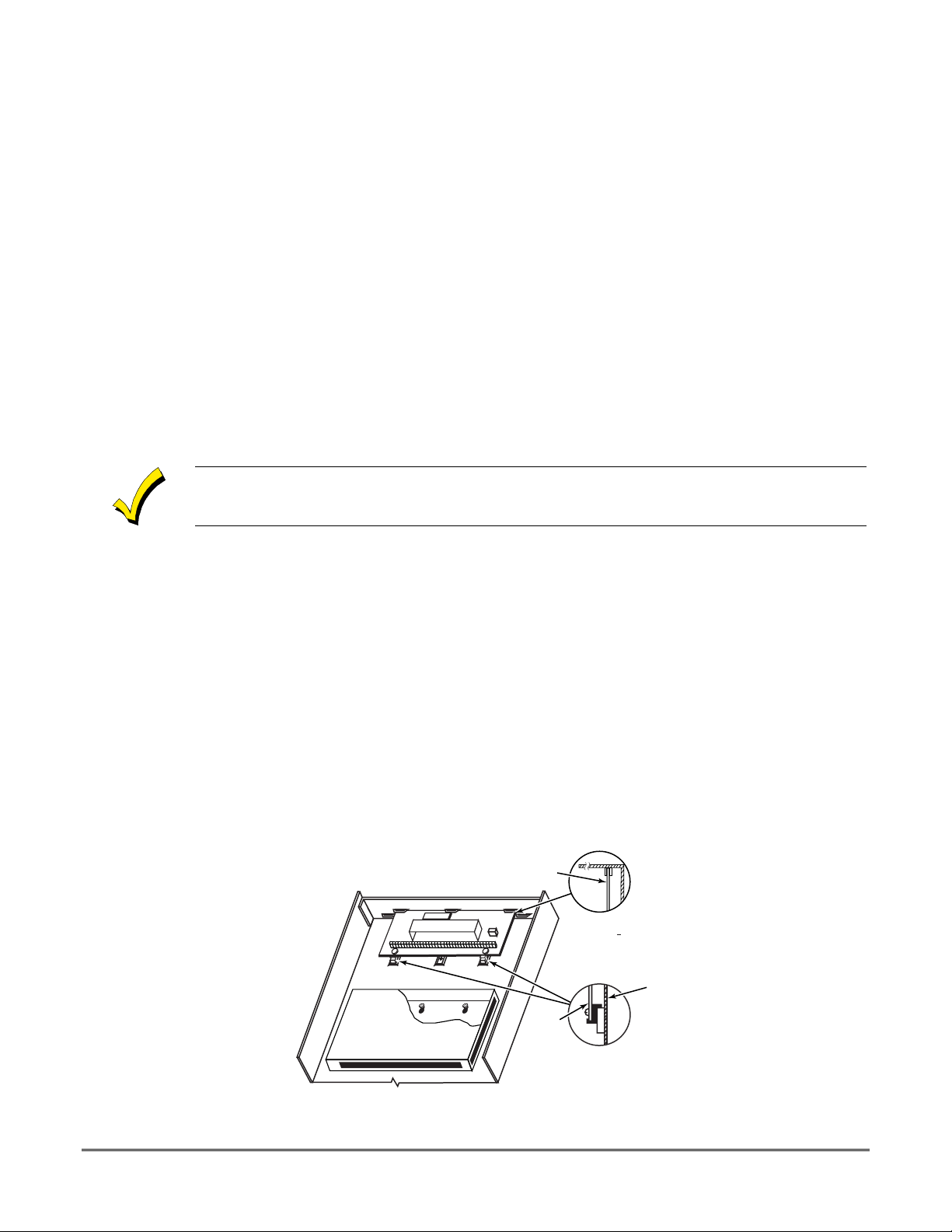
Mounting the Control's Circuit Board Alone in the Cabinet
To mount the circuit board alone in the cabinet, follow these steps:
1. Hang two mounting clips* (provided ) on the raised cabinet tabs (see Detail B in Figure 2
below).
2. Insert the top of the circuit board between the rows of slots at the top of the cabinet as
shown in Detail A.
3. Position the base of the board onto the mounting clips and secure both to the cabinet with
the supplied screws (see Detail B).
*
These mounting clips are also used for mounting the same end of the circuit board when an RF
receiver is mounted above it, as in Figure 3.
CABINET
CIRCUIT BOARD
+
+
CIRCUIT
BOARD
DETAIL A
SIDE VIEW
OF BOARD
SUPPORTING
SLOTS
CABINET
DETAIL B
SIDE VIEW
OF MOUNTING
CLIPS
Figure 2. Mounting the Control's Circuit Board Alone in the Cabinet
Mounting the Control and RF Receiver Circuit Board in the Cabinet
To mount the control and RF receiver boards together in the cabinet, do the following:
1. Hang two mountin g clips (p rovid ed with receiv er) o n the raise d cabine t tabs, as shown in
Detail B in Figure 3.
2. Insert the top of the receiver board (removed from its own case as described in its
instructions) between the rows of slots at the top of the cabinet, as shown i n Detail A.
3. Position the base of the receiver board onto the mounting clips and secure both to the
cabinet with the supplied screws (see Detail B).
4. Hang two mounting clips (supplied with the contro l board), on the raise d cabinet tabs as
shown in Detail C in Figure 3.
5. Insert the top of the control board into the slots of the mounting clips secured in step 3
above.
6. Position the lower end of the control board into place on the mounting clips and secure
both to the cabinet with the two supplied screws.
7. Insert both grounding lugs (supplied with the receiver) through the top of the cabinet
into the left-hand terminals of the antenna blocks (located at the upper edge of the
receiver board), and secure them to the cabinet with the screws provided, as shown in
Detail D.
8. Insert the receiv er's antennas thr ough the top of the cabinet, into the bloc ks' right-hand
terminals, and tighten the screws.
Refer to setup and wiring instructions for the receiver in the WIRELESS EXPANSION (5800
RF SYSTEMS) section.
V10SE-003-V0
2-2
Section 2 - Installing the Control
BOARD
SUPPORTING
SLOTS
MOUNTING
CLIP
MOUNTING
CLIP
CABINET
HOLES FOR ANTENNAS
AND GROUNDING LUGS
RECEIVER CIRCUIT BOARD
(See Detail D)
++
CONTROL
CIRCUIT
BOARD
SCREW
(2)
GROUNDING
LUG
(2)
RCVR BRD
++
ANTENNA AND GROUNDING LUG INSTALLATION
DETAIL D
ANTENNA
(2)
CIRCUIT BOARD
ANTENNA
MOUNT
(2 PLACES)
CABINET
DETAIL A
SIDE VIEW
OF BOARD
SUPPORTING SLOTS
DETAIL B
SIDE VIEW
OF MOUNTING
CLIP
DETAIL C
SIDE VIEW
OF MOUNTING
CLIP
V10SE-004-V0
Figure 3. Mounting the PC Board and RF Receiver Together in the Cabinet
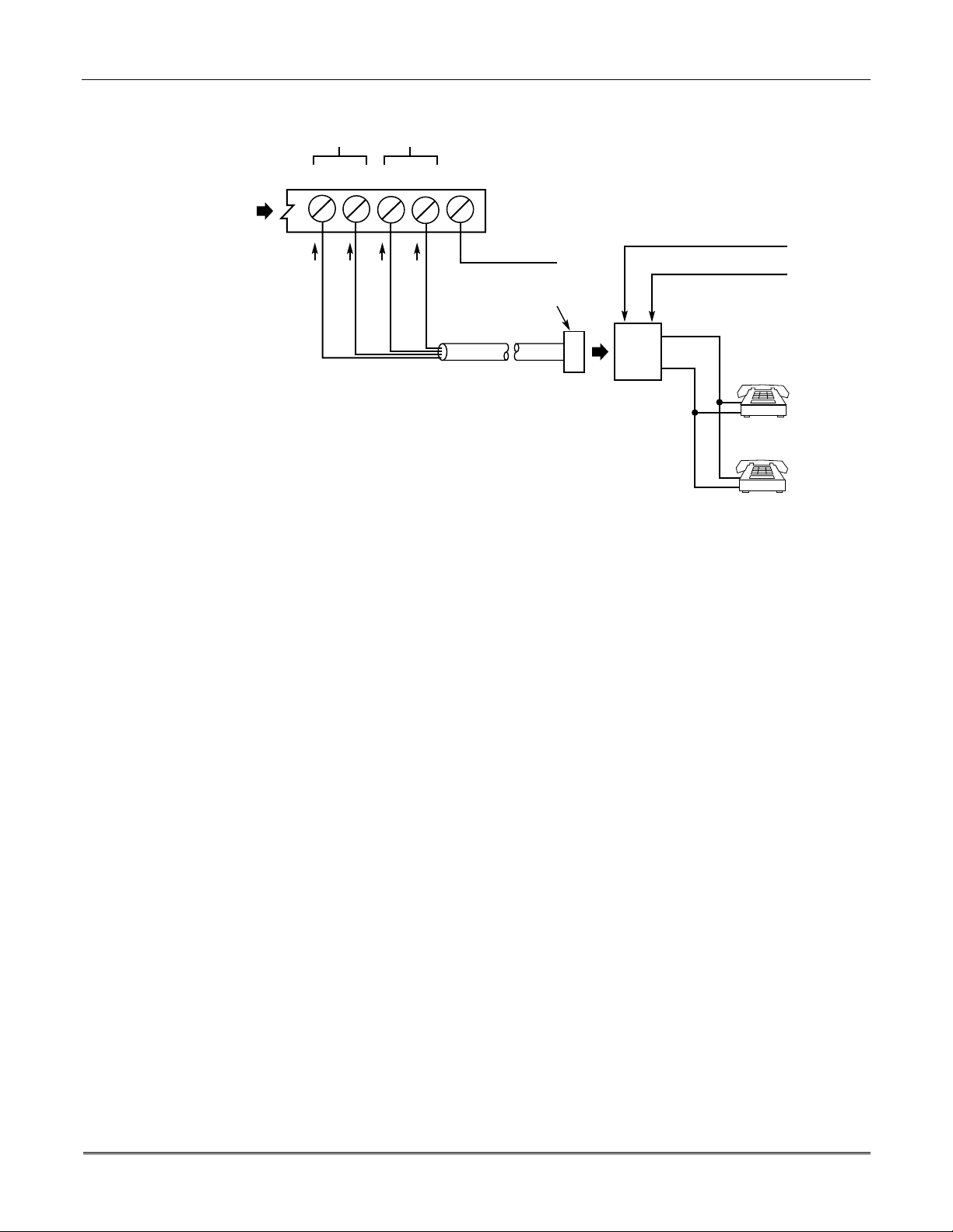
Standard Phone Line Connections
The wiring connections shown here are not applicable if a 4285/4286 VIP Module is used. Refer
to the
4285/4286 VIP MODULE
are different than those shown here.
Connect incoming phone line and handset wiring to the main terminal block via an RJ31X
jack (CA38A jack in Canada) as follows and as shown in Figure 4.
Term. 17: Local Handset (TIP – Brown*).
Term. 18: Local Handset (RING – Gray*).
Term. 19: Incoming Phone Line (TIP – Green*).
Term. 20: Incoming Phone Line (RING – Red*).
*
Colors of wires in Direct Connect Cord.
section for information regarding phone line connec tions , whic h
2-3
VISTA-10SE Installation and Setup Guide
HANDSET
17 18 19 20 21
TERMINALS
ON CONTROL
INCOMING
TELECOM
LINE
GROUND
BROWN (TIP)
GREY (RING)
GREEN (TIP)
RED (RING)
EARTH GROUND
PLUG
DIRECT
CONNECT
CORD
INCOMING TELECOM LINE
TIP
RING
RJ31X
JACK
Figure 4. Standard Telephone Line Connections
TIP
RING
PREMISES
PHONES
V10SE-024-V0
2-4

SECTION 3
Remote Keypads
••••••••••••••••••••••••••••••••••••••••••••••••••
In This Section
Keypads That May Be Used
♦
Wiring to the Keypads
♦
Mounting the Keypads
♦
••••••••••••••••••••••••••••••••••••••••••••••••••
This section lists the wired keyp ads that may be used and provides instruction s for wiring
and mounting the keypads.
A preliminary checkout procedure is also provided to ensure that the connected keypads are
functioning properly in the syst em.
Supplementary Power for Additional Keypads
♦
Preliminary Checkout Procedure
♦
Keypads That May Be Used
• Fixed-Word Display: 6127, 6128, 6137
• Alpha Display: 6138, 6139
• Up to 4 keypads, independe nt of auxiliary power con siderations (yo u may need to use an
auxiliary power supply if the 500mA aux. output is exceeded)
If you are going to use a 4285/4286 VIP Module, you MUST use addressable key pads (6128,
6137, 6138, 6139) in the system, but set to the non-addressable mode (address 31).
Wiring to the Keypads
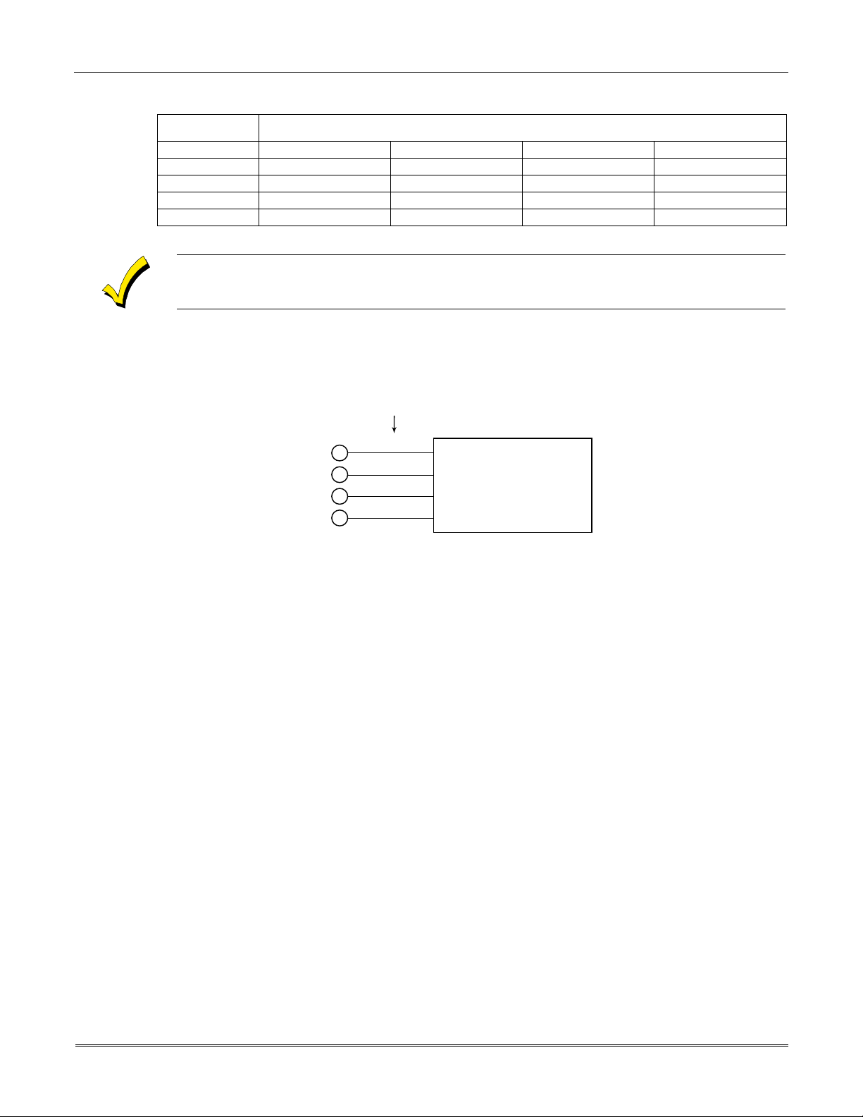
1. Determine wire gauge by referring to the wiring length/gauge chart below.
For devices (keypads, RF receivers, etc.) connected to a single 4-wire run, determine the
current drawn by all units connected to the single wire run, then refer to the Wiring Run
chart to determine the maximum wire length that can be safely used for each wire size.
Current draw for all devices can be found in the
section.
NOTE: Refer to “Auxiliary Dev ice Current Draw Wo rksheet” in the
section for current draw for all keypads.
Maximum wire lengths for any device that is homerun to the c ontrol can also be determined
from the chart, based on the current draw of that device
SPECIFICATIONS & ACCESSORIES
FINAL POWER-UP
alone
.
3–1
VISTA-10SE Installation and Setup Guide
5
6
7
4
CONTROL
TERMINALS
BLACK
RED
GREEN
YELLOW
V10SE-026-V0
KEYPADS
KEYPAD CONNECTOR CABLE
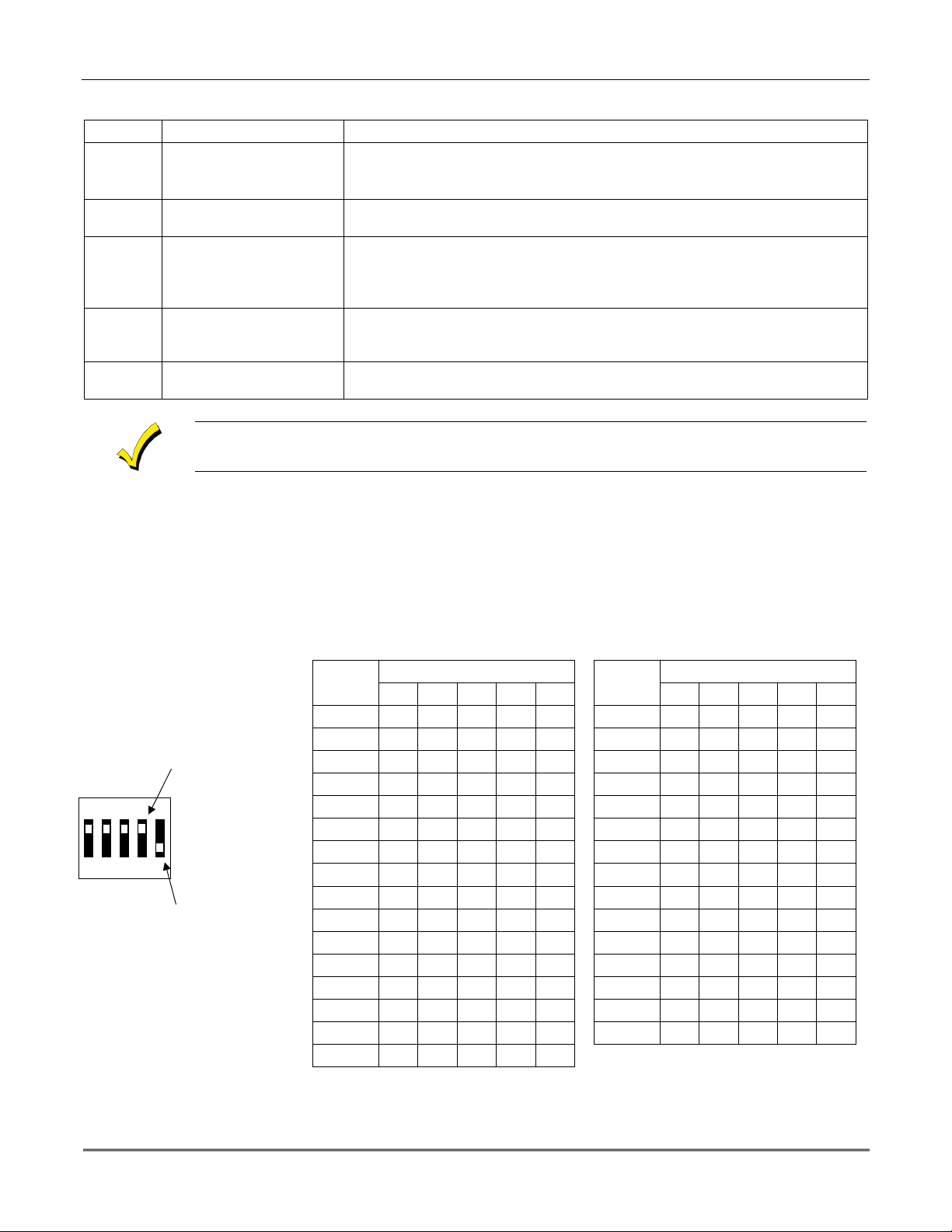
Wiring Run Chart for Devices* Drawing Aux Power From the Control (12V+ & 12V–)
TOTAL CURRENT DRAWN BY ALL DEVICES CONNECTED TO A SINGLE WIRE RUN
Wire Size 50mA or less 100mA 300mA 500mA
#22 500 ft (152m) 250 ft (76m) 80 ft (24m) 50 ft (15m)
#20 750 ft (228.6m) 380 ft (116m) 130 ft (39.6m) 80 ft (24m)
#18 1300 ft (396m) 650 ft (198m) 220 ft (67m) 130 ft (39.6m)
#16 1500 ft (457m) 1000 ft (305m) 330 ft (100.5m) 200 ft (70m)
*
Includes keypads, RF receivers, relay units, and 4285/4286 VIP Modules.
The length of all wire runs must not exceed 1500 feet ( 457m) when unshielded quad c onductor
cable is used (750 feet if shielded cable is used) . This restric tion is due to the capacitive effect
on the data lines
when quad cable is used.
2. Run field wiring from the control to the keypads (using standard 4-conductor twisted
wire cable using the wire gauge determined in step 1).
3. Connect remote keypads to terminals 4, 5, 6, and 7 on the control board, as shown in
Figure 5.
Figure 5. Keypad Connections to the Control Board
Mounting the Keypads
1.
Make sure addressable-type keypads
addressable mode (address 31), which is the factory default setting. Refer to the
instructions provided with the keypad for address setting procedure.
2.
Mount the keypads
at a height that is convenient for the user. Refer to the instructions
provided with the keypad for mounting procedure.
You can either surface mount or flush mount keypads (using an appropriate Trim Ring
Kit: 6139TRK). Refer to the mounting instructions and template included with the
keypad and/or trim ring kit for specific information.
Supplementary Power for Additional Keypads
The control provides 500mA for powering keypads (up to a maximum of 4) and o ther devices
from the auxiliary po wer output. The backup battery w ill supply power to th ese keypads in
the event that AC power is lost.
When the control’s auxiliary power load for all devices exceeds 500mA, you can power
additional keypads from a regulated, 12VDC power supply (e.g., 487-12 supplies 12V, 250mA;
488-12 supplies 12V, 500mA). Use a UL Listed, battery-backed supply for UL installations.
The 487-12/488-12 power supplies have a backup battery that can power these keypads in the
event of AC power loss.
(6128, 6137, 6138, and 6139) are set to non-
3-2
Section 3 - Installing Remote Keypads
Keypads powered from supplies that do not have a bac kup battery
will not function
when AC
power is lost. Therefore, be sure to power at least one keypad from the Control's auxiliary
power output.
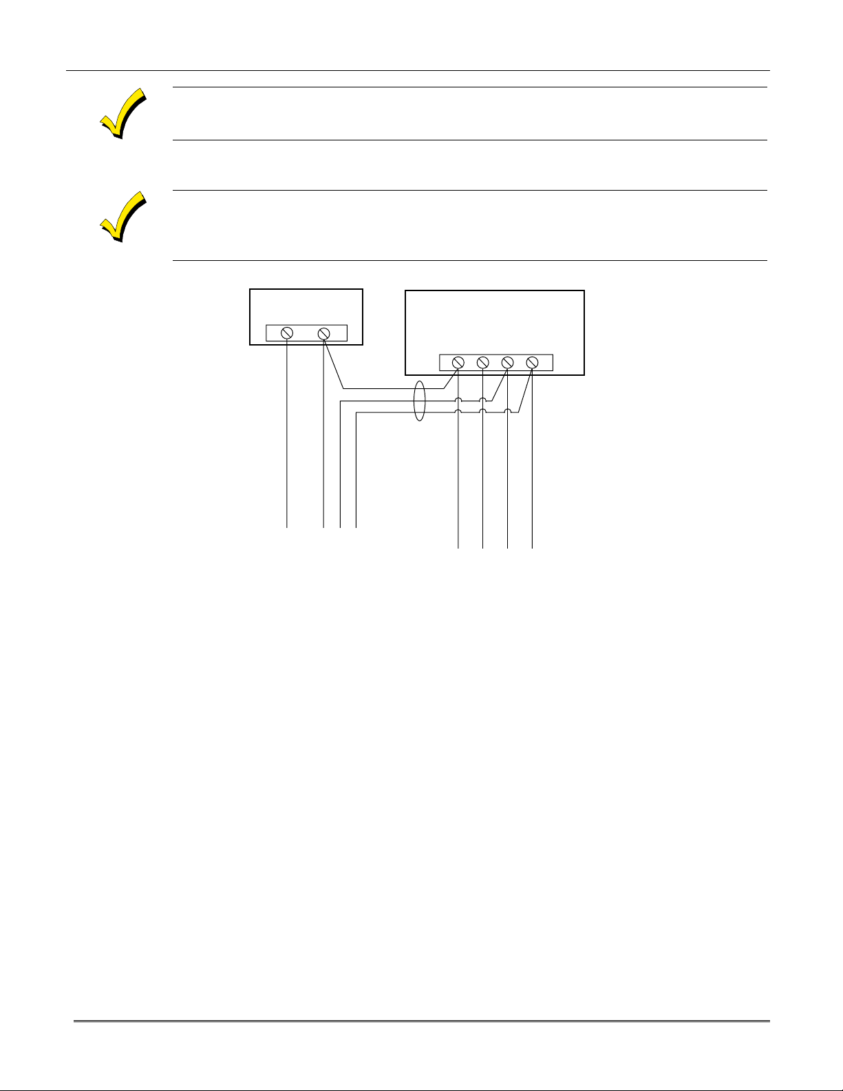
Connect the additional keypads as shown in Figure 6, using the keypad wire colors shown. Be
sure to observe the current ratings for the power supply used.
Make connections directly to the sc rew terminals as shown in
Figure 6
. Make no connection to
the keypad blue wire (if present).
Be sure to connect the negative (–) terminal on the Power Supply unit to ter minal 4 (AUX – ) on
the control.
SUPPLEMENTARY
POWER SUPPLY
+
–
TO KEYPAD RED WIRE
TO KEYPAD BLK WIRE
TO KEYPAD GRN WIRE
IMPORTANT:
MAKE THESE
CONNECTIONS
DIRECTLY TO
SCREW
TERMINALS AS
SHOWN.
TO KEYPAD YEL WIRE
CONTROL TERMINAL STRIP
AUX. DATA
AUX.
+
–
456 7
TO KEYPAD BLK WIRE
DATA
IN
OUT
TO KEYPAD RED WIRE
TO KEYPAD GRN WIRE
TO KEYPAD YEL WIRE
V10SE-008-V0
Figure 6. Using a Supplementary Power Supply for Keypads
Preliminary Checkout Procedure
If you want to check that the system is working before connecting field wiring from zones and
devices, do the following:
1. Temporarily connect a 1000 ohm end-of-line resistor across each of the basic hardwire
zones 1–6, as shown in the Summary of Connections diagram.
Without actual zone wiring or EOL resistors connected, the key pads in the system will not
display the “Ready” message.
2. Power-up the system temporar ily by plugging the AC transformer (previously wired to the
control) into a 120VAC outlet.
–
3. Busy
After approximately 1 minute*, the green READY LED (or POWER LED on some types of
keypads) should light, and the word "
"
DISARMED...READY TO ARM"
is functioning properly.
* To bypass the 1-minute delay, press # + 0.
Standby (on alpha keypads) or
dI
(on fixed-word keypads) will be displayed.
READY"
(on fixed-word keypads) or the words
(on alpha keypads) sh o uld be di splay e d, ind ica ting the sy ste m
3-3

VISTA-10SE Installation and Setup Guide
If the “Ready” message is not displayed on any of the keypads in the system, or a “Not
Ready” message is displayed, check the keypad wiring connections, and make sure each of
the 6 basic hardwired zones has a 1000 ohm resistor connected across its terminals.
Do not remove the EOL resistors until you are ready to make connections to the hardwired
zones, to allow for testing later in the manual.
If an OC or OPEN CIRCUIT display is present on the keypad, data from the control is not
reaching the keypad. Check the wiring.
3-4

SECTION 4
Basic Hardwired Zones 1–6
••••••••••••••••••••••••••••••••••••••••••••••••••
In This Section
Installing the Hardwired Zones
♦
Programming Hardwired Zones
♦
••••••••••••••••••••••••••••••••••••••••••••••••••
Installing the Hardwired Zones
Common Characteristics for Zones 1–6
•
Response time from 300 - 500 milliseconds (400 milliseconds nominal).
•
Zone 3 can be programmed (in field
(10mSec max) to an open (suitable for vibration type contacts). Default response is
400mSec nominal, which should be used for most standard contacts.
•
EOLR supervised zones support both open-circuit and closed-circuit devices.
•
As many 4-wire smoke detectors as can be powered from Aux Power on the control (on
zone 5).
52) for normally-closed sensor fast response
✱
U
L
Wiring Burglary and Panic Devices to Zones 1–6
Wiring 4-Wire Smoke/Combustion Detectors on Zone 5
4-Wire Smoke/Combustion detectors are
To wire burglary and panic devices to zones 1-6, perform the following steps, referring to
Figure 17. VISTA-10SE Summary of Connections
1. Connect sensors/contacts to the hardwired zone terminals (8 through 16). See the
Summary of Connections diagram.
2. Connect closed circuit devices in series i n the high (+) side of the loop. The EOL resistor
must be connected in series with the devices, following the last device. See the Summary
of Connections diagram.
3. Connect open circuit devices in parallel across the loop. The 1000 ohm EOLR must be
connected across the loop wires
If the EOLR is not at the end of the loop, the zone will not be properly supervised, and the
system may not respond to an open circuit on the zone.
The system will support as man y 4-wire detectors as can be pow ered from Auxiliary Po wer
on the control on zone 5. Refer to the detector’s instructions for complete d etails re g arding its
proper installation a nd operation.
1. Co nnect 12-volt power for th e detectors from Auxiliary Power terminals 4 and 5 (which
will interrupt power for fire alarm reset). Observe proper polarity when connecting
detectors. See
2. Connect detectors (including heat detectors, if used) across terminals of zone 5. All
detectors must be wired in parallel.
Figure 7
.
not
at the last device.
permitted in UL installations.
on the inside back cover of this manual.
Remove 1000 ohm EOL resistor if connected across the zone terminals. You mus t connect the
EOL resistor across the loop wires at the last detector.
4–1
VISTA-10SE Installation and Setup Guide
3. To meet NFPA 72 requirements, you must use a supervisory module to supervise power
(e.g., System Sensor No. A77-716B Relay module).
5
AUX PWR
OUTPUT
TERMINALS
+
_
4
+
TO HI SIDE OF
ZONE 5
TO LO SIDE
+
HEAT
DETECTOR
_
Figure 7. 4-wire Smoke Detector Connections (Zone 5)
4-WIRE SMOKE
OR COMBUSTION
DETECTORS
_
DETECTOR
HEAT
BLK
+
_
_
VIOLET
1000
OHMS
EOLR
+
RED
EOL
POWER
SUPERVISION
RELAY MODULE
A77-716B
V10SE-010-V0
Compatible System Sensor 4-Wire Smoke/Combustion Detectors
1412
2412
2412TH
A77–716B
2112/24T
4-wire ionization products of combustion detector
4-wire photoelectric smoke detector
4-wire photoelectric smoke detector w/135°F (57°C) heat detector
EOL relay module (supervisory module for wired 4-wire fire zone)
Low-profile 4-wire photoelectric smoke detector w/135°F (57°C) heat
detector
Programming Hardwired Zones
Each zone must be programmed into the system using the ✱56 Zone Programming Mode or
✱
58 Expert Programming Mode, which assigns characteristics that define the way the system
responds to faults on that zone. Refer to the ZONE RESPONSE TYPE DEFINITIONS and
ZONE PROGRAMMING sections for specific instructions on programming hardwired zones.
4-2

SECTION 5
Wireless Expansion
••••••••••••••••••••••••••••••••••••••••••••••••••
(5800 System)
In This Section
About Wireless Expansion
♦
Installing the 5881/5882 Receiver
♦
Installing the 5800TM Module
♦
••••••••••••••••••••••••••••••••••••••••••••••••••
About Jam Detection and Reporting
♦
5800 Series Transmitters
♦
Installing 5800 Series Transmitters
♦
About Wireless Expansion
The VISTA-10SE supports up to 16 wireless zones that may be used exclusively or in
addition to hardwired zones 1 through 6.
The receiver detects signals from
The following 5881 Receivers may be used with this system (5882 in Canada), and each
supports the number of zones shown:
RF Receiver No. of Zones
5881L/5882L up to 8
5881M/5882M up to 16
5881H/5882H up to 16
wireless transmitters
within a nominal range of 200 feet.
U
L
Receiver Supervision
House Identification
Wireless may not be used in UL Commercial Burglary installations.
In Canada
Series of receivers applies as well to the 5882 Series. 5881 and 5882 Series receivers can
support the same 5800 type transmitters.
Any zone
with the number of zones that can be used, which is shown in table above).
The receiver is supervised. The following conditions cause a Trouble report to be generated
and CHECK and ZONE 09 messages to be displayed:
•
Communication between the panel and the receiver is interrupted.
or
No
•
If you are using a 5804BD, 5827, or 5827BD Wireless Keypad with the system, you must
program a House ID Code (01-31) in field
must be set to the same ID.
12 hours.
valid
, 5800 systems must use 5882 Series receivers. Information relative to the 5881
number
from 10–25 can be used as a 5800 Series wireless zone (do not confuse this
RF signals from at least one supervised wireless transmitter are received within
✱
24 to establis h proper communication. The keypad
House ID 00 disables all wireless keypads.
5–1
VISTA-10SE Installation and Setup Guide
Installing the 5881/5882 Receiver
RF System Installation Advisories
Follow the guidelines below when installing the RF receiver. (Disregard if the receiver is
mounted in the control cabinet.)
Installation and Setup of the 5881/5882 Receiver
ON OFF
5
4
3
2
1
Place the
•
Do not locate the receiver or transmitters on or near metal objects. This decreases range
•
RF receiver
in a high, centrally located area for best reception.
and/or block transmissions.
Do not locate the receiver in an area of high
•
interference (revealed by frequent or
RF
prolonged lighting of the LED in the receiver; random flicker is OK).
The RF receiver must be at least 10 feet from any remote keypads to avoid interference
•
from the microprocessors in those units.
To install the recei ver, take the following steps (refer to
1. Set the receiver's
< <
switches shown at l eft are in the OFF posit ion).
DIP switch
for device address 0, as described in its instructions (all
Figure 8
below):
2. Mount the receiver. The RF receiver can detect signals from transmitters within a
nominal range of 200
feet
. Take this into consideration when determining mounting
location.
3. Connect the
receiver's
wire harness to the control's keypad terminals (4, 5, 6, and 7). Plug
the connector at the other end of the harness into the receiver.
4. Refer to the
installation
instructions provided with the receiver for further installati on
procedures regarding antenna mounting, etc.
MOUNTING
HOLES
CIRCUIT
BOARD
ANTENNAS
INSERT IN
RIGHT-HAND
TERMINALS
DIP SWITCH
DIP SWITCH #5 (PRESET ONLY ON 5881EH)
ON: SETS 5881EH FOR USE IN COMMERCIAL
FIRE APPLICATIONS (SEE THE RECEIVER'S
INSTRUCTIONS)*.
OFF: USE IN NON-COMMERCIAL FIRE
INSTALLATIONS.
* FOR COMMERCIAL FIRE APPLICATIONS
THE 5881EH PC BOARD MUST BE MOUNTED
IN A SEPARATE CABINET (SEE RECEIVER'S
INSTRUCTIONS FOR DETAILS).
INTERFERENCE
INDICATOR LED
PLUG & SOCKET
YELLOW
RED
BLACK
GREEN
WIRING
OPENING
TO CONTROL'S REMOTE KEYPAD
CONNECTION POINTS. EACH RECEIVER
MUST BE ON INDIVIDUAL HOME RUN.
USE MAX. of 220 ft. [67m of #22 (0.64mm)
WIRE or 550 ft. (168m) of #18 (1mm) WIRE
FOR EACH RUN]. OBSERVE 20 ft. MAX.
FOR COMMERCIAL FIRE INSTALLATIONS.
(SEE RECEIVER'S INSTRUCTIONS.)
DIP SWITCH WHITE AREAS = SWITCH
HANDLES. POSITIONS 2-4 DETERMINE
RECEIVER'S ADDRESS. CONSULT
CONTROL'S INSTRUCTIONS FOR
ADDRESS TO USE. DIP SWITCH BELOW
SHOWN SET FOR ADDRESS "0."
SWITCH
POSITION
Figure 8. 5881/5882 RF Receiver (cover removed)
RECEIVER ADDRESS SETTINGS
(" - " MEANS OFF)
0 1 2 3 4 5 6 7
PRESENT ONLY ON 5881EH (SEE TEXT AT LEFT)
5
4
3
2
1
ON ON ON
ON
ONON
FOR FUTURE USE
ONON
ONON ONON
5-2

Installing the 5800TM Module
Installation of this module is necessary only if you are using one or more 5827BD Wireless
Bi-directional keypads, 5804 or 5804BD Transmitters (wireless keys).
Mounting the 5800TM Module
The 5800TM must be located next to the RF receiver (between one and two feet from the
receiver’s antennas). The 5800TM must not be installed within the control cabinet. Mount
the unit using its accompanying mounting bracket.
Wiring the 5800TM Module
Connect the 5800TM to the control panel’s keypad connection terminals, using the supplied
connector with flying leads, as follows:
Wire Terminal on Control
BLACK (Ground) Terminal 4
RED (+12VDC) Terminal 5
GREEN (Data to Control) Terminal 6
YELLOW (Data from Control) Terminal 7
BLUE Not Used
Do not cut any of the jumpers on the 5800TM when using it with the VISTA-10SE.
For additional information, refer to the 5800TM’s instructions.
Section 5 - Wireless Expansion
About Jam Detection and Reporting
When field ✱22, option 4 (RF SYSTEM) is selected, a 5800 Series receiver detecting a jam
condition sends an E344 (RF Receiver Jam Detect) Contact ID report to the central station.
At the same time, a Rcvr Jam (on alpha keypads) or CHECK 90 (on fixed-word keypads)
message alternates with the present system message on the keypad. When the jam condition
is cleared, a Restore message is sent to the CS. Entering a code and OFF restores the
keypad display.
The default for this option is 0 (disabled).
Normal use of a 5827 wireless keypad may cause a false RF jam message to be displayed in
systems that have been programmed for RF Jam Detection.
5800 Series Transmitters
Programming Wireless Zones
5800 Series transmitters have built-in serial numbers that must be enrolled” into the system
✱
using the
the control via the downloader. 5800 Series transmitters (except 5827, described separately)
do not have DIP switches.
Program each transmitter's zone number into the system using
Zone Programming section). Some transmitters, such as the 5816 and 5817, can support
more than one “zone” (referred to as loops or inputs). On the 5816, for example, the wire
connection terminal block is loop 1, the reed contact is loop 2. Each loop must be assigned a
different zone number.
56 or ✱58 programming modes in the ZONE PROGRAMMING section, or input to
✱
56 or ✱58 mode (refer to the
U
L
The 5816 and 5817 transmitters do not have EOL supervision of their loop wiring. Therefore, for
UL Household Burglary installations, the loop wiring may not exceed 3 feet.
5-3

VISTA-10SE Installation and Setup Guide
For button transmitters (RF keys), such as the 5801, 5804, and 5804BD, you must assign a
unique zone number to each individual button used on the transmitter. Each button on the
transmitter also has a pre-designated loop or input number, which is automatically displayed
on the keypad.
Programming an RF House ID
Programming an RF House ID (01–31) in field
5827BD Wireless Keypads or 5804BD Transmitters. An RF House ID is not necessary for
other 5800 Series Transmitters, and the entry should be left at 00 (default) in those cases.
The 5827 reports low-battery status as zone 00.
Transmitter Supervision
Except for some transmitters that may be carried off-premises (5802, 5802CP, 5803, 5804,
5804BD, 5827, and 5827BD), each transmitter is supervised by a check-in signal that is sent
to the receiver at 70-90 minute intervals. If at least one check-in is not received from each
supervised transmitter within a 12-hour period, the “missing” transmitter number(s) and the
message CHECK is displayed.
In accordance with ULC standards, the RF supervision period for the VISTA-10SE is three hours
for fire zones (Zone Type 9) and 12 hours for all other zone types.
✱
24 is necessary only if you are using 5827 or
The supervision for a particular transmitter in the system that may also be carried off the
premises (5801, 5802MN) may be turned off by enrolling it as a “UR” (unsupervised RF) type,
as described later.
5800 Series transmitters have built-in tamper protection and annunciate as a Check
condition if covers are removed.
Transmitter Input Types
All of the transmitters described have one or more unique, factory-a ssigned input (loop) ID
codes. Each of the inputs requires its own programming zone (for example: a 5804's four
inputs require four programming zones). Refer to the ZONE PROGRAMMING section.
Transmitters can be enrolled as one of the following types:
Type Description
RF
(Supervised RF)
UR
(Unsupervised RF)
BR
(Unsupervised Button RF)
Transmitter Battery Life
Sends periodic check-in signals, as well as fault, restore, and lowbattery signals. The transmitter must remain within the receiver's
range.
Sends all the signals that the “RF” type does, but the control does
not supervise the check-in signals. The transmitter may therefore be
carried off-premises.
Sends only fault signals. It will not send a low-battery signal until it is
activated. The transmitter may be carried off-premises.
5-4
Do not install batteries in wireless transmitters until you are ready to enroll the transmitters
during system programming. After enrolling, batteries need not be removed.
Batteries in the wireless transmitters may last from 4 to 7 years, depending on the
environment, usage, and the specific wireless device being used. Factors such as humidity,
extreme temperatures, as well as large temperature variations may all reduce the actual
battery life in a given installation.

The wireless system can identify a true low-battery situation, thus allowing the dealer or
user of the system time to arrange a change of battery and maintain protection for that point
within the system.
Some transmitters (e.g., 5802, 5802CP, and 5804) contain long-life but nonreplaceable
batteries, and no ba ttery installati on is required. At the end of their life, the complete unit
must be replaced (and a new serial number enrolled by the control).
Button-type transmitters (such as 5801, 5802, 5802MN/MN2, 5802CP, and 5804) should be
periodically tested for battery life.
The 5802MN and 5804 Button Transmitters have replaceable batteries.
Using the Transmitter Sniffer Mode
The Transmitter Sniffer mode is a procedure that verifies that all transmitters have been
properly programmed. To verify programming, refer to the TESTING THE SYSTEM section.
5800 Series Transmitters Table
Model Description Input Type and Special Notes
5801 Wireless Panic
Transmitter
5802
5802CP
5802MN
5802MN
5804
5804BD
5806
5807
5808
5807L
5807LT
5807LST
5808LST
5809
5816
5816MN
5816
5817 Multi-Point Universal
Pendant Belt Clip
(Personal Emergency)
Transmitters
Miniature Personal
Emergency Trans.
2
Wireless Key
Transmitter
Wireless Photoelectric
Smoke Detectors
Low-profile version
of the Wireless
Photoelectric Smoke
Detectors
HeatSensor, 135
Detector/Transmitter
Door/Window
Transmitter
TEMP
Low Temp Sensor
Transmitter
º
Enroll as “3” for RF (supervised), or “4” for UR (unsupervised).
Unit has 4 pushbuttons, each with a unique input (loop) code.
Each pushbutton must be assigned to a zone.
Input loop (button) No. 4 must always be used.
NOTE:
Enroll as “5” for BR (button-type transmitter).
Enroll as “3” for RF (supervised), or “4” for UR (unsupervised).
Single pushbutton-type transmitter.
Enroll as “5” for BR (button-type transmitter).
Has 4 pushbuttons, each with a unique input (loop) code.
Each pushbutton must be assigned to a zone.
All buttons must be assigned the same input type.
NOTE:
Enroll as “3” for RF (supervised).
At the “INPUT S/N” prompt, fault the detector as follows:
On many detectors, you must press a special test switch (not test button) to
1.
fault the
NOTE:
detector. Disengage the detector’s cover and swing it open. These contacts
are on the PC board near a blue jumper (see detector’s instructions).
Momentarily short these contacts with a small screwdriver.
Two keypad beeps occur when the detector is faulted the first time.
Wait 6 to 8 seconds, then press and release the test switch (or momentarily
2.
short the contacts) again. If the control has accepted the input code, 3 beeps
sound and the enrolled input (loop) number is displayed.
Enroll as “3” for RF (supervised).
Has two unique input (loop) zones: one for a wired closed-circuit contact loop,
and the other for a built-in reed switch (used in conjunction with a magnet).
Either or both may be used.
Enroll as “3” for RF (supervised).
Has three unique input (loop) codes: one for a DIP switch-set “Primary” contact
loop, and the others for two “Auxiliary” closed-circuit contact loops.
The “Primary” loop may be set for:
•
•
•
3-Minute or no Transmission Inhibit
detector
With some detectors, you must short two contacts to fault the
Repeating or Single Transmission
Normally Open or Normally Closed circuit
Slow or Fast Response
(see detector’s instructions).
Section 5 - Wireless Expansion
5-5
VISTA-10SE Installation and Setup Guide
5800 Series Transmitters Table (
Model Description Input Type and Special Notes
5817
(cont'd.)
Multi-Point Universal
Transmitter
(cont'd.)
5818 Recessed Magnetic
Contact Transmitter
5819
5819
5819
5849
5850
Shock Processor
Transmitter
BRS
WHS
Glassbreak
Detector/Transmitter
5852
5890
5890P1
PIR Detector/
Transmitter
DIP Switches:
All loops must be assigned the same input type.
NOTE:
Enroll as “3” for RF (supervised).
Enroll as “3” for RF (supervised).
Has three unique input (loop) zones: one for a wired closed-circuit contact loop,
one for use with inertia-type shock detectors (mounted externally), and one for a
built-in reed switch (used in conjunction with a magnet).
Enroll as “3” for RF (supervised).
Enroll as “3” for RF (supervised).
The cover must be on the unit when enrolling the serial number.
Set all DIP switches to the OFF position when enrolling the
serial number.
When “enrolling” a transmitter’s ID code(s), any PIR in the vicinity that is not being enrolled
should be covered with a cloth, tissue, etc. to prevent activation.
Installing 5800 Series Transmitters
To be sure reception of the transmitter's signal at the proposed mounting location is
adequate, perform a Go/No Go Test in the TESTING the SYSTEM section.
continued)
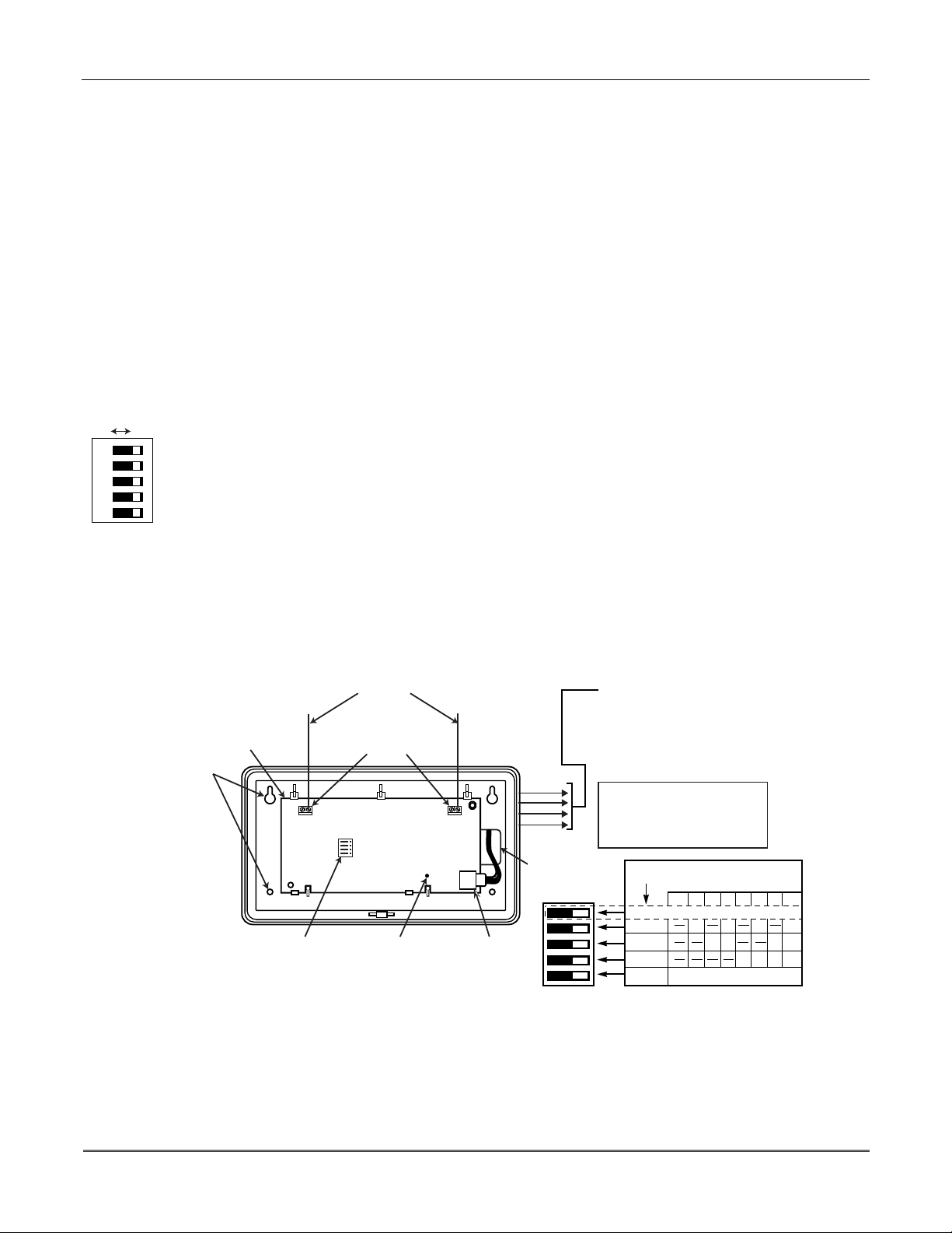
Setting DIP Switches on the 5827 Transmitter(s)
You must set a 5827 Transmitter to the programmed House ID, using its DIP switches.
SWITCH UP FOR "ON"
SWITCH DOWN FOR "OFF"
SHOWN SET FOR
HOUSE ID # 30
DIP SWITCH POSITION
12345
1 ----UP
2 ---UP3 - - - UP UP
4--UP-5--UP-UP
6--UPUP7 - - UPUPUP
8 -UP--9 - UP - - UP
10 - UP - UP 11 - UP - UP UP
12 - UP UP - 13 - UP UP - UP
14 - UPUPUP 15 - UPUPUPUP
16UP----
DIP SWITCH POSITIONHOUSE
ID
17 UP - - - UP
18 UP - - UP 19 UP - - UP UP
20 UP - UP - 21 UP - UP - UP
22 UP - UP UP 23 UP - UPUPUP
24 UP UP - - 25 UP UP - - UP
26 UP UP - UP 27 UP UP - UP UP
28 UP UP UP - 29 UP UP UP - UP
30 UP UP UP UP 31 UP UP UP UP UP
12345
5-6
SECTION 6
Relay Output Devices
••••••••••••••••••••••••••••••••••••••••••••••••••
In This Section
Relay Device Basics
♦
4204 Relay Modules
♦
Programming Options
♦
••••••••••••••••••••••••••••••••••••••••••••••••••
Relay Device Basics
Relays are programmable switches that can be used to perform many different functions.
They can be used to turn lights on and off, control sounders, or for status indications. In this
system, each relay must be programmed as to how to act (ACTION), when to activate
(START), and when to deactiva te (STOP). Each of these is described below.
The control supports a total of 4 output relays.
The 4204 Relay modules provide Form C (normally open and normally closed) contacts.
In ✱80 and ✱81 interactive modes, a series of keypad prompts will request entries for
programming of the Relay outputs used in the system. Refer also to “OUTPUT RELAY
✱
DEVICE WORKSHEET FOR
80 AND ✱81 INTERACTIVE MODES” in the blank
programming form provided in the separate Programming Form manual.
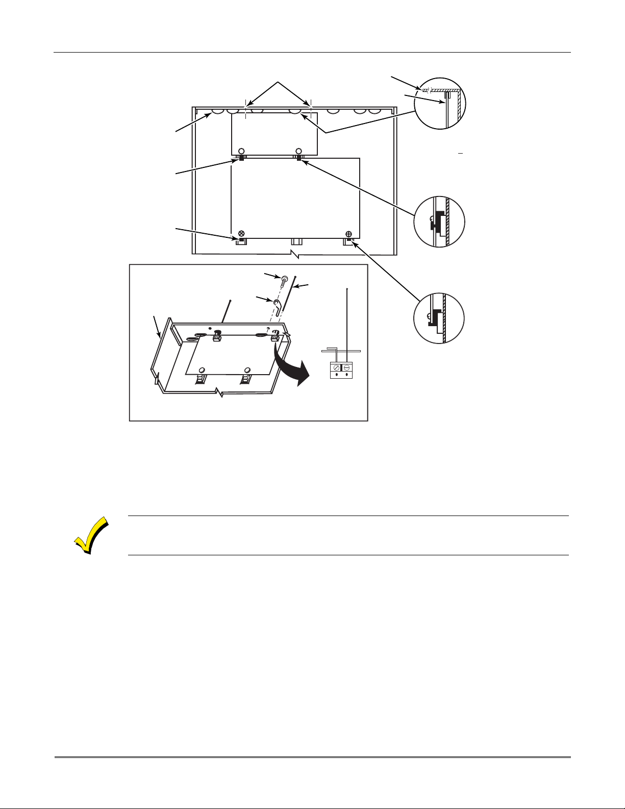
4204 Relay Modules
4204 Relay Unit (if installed in cabinet)
1. Insert self-tap pin g screw s (prov ide d ) in two adj ace nt raise d cabin e t tabs. Leav e the he ads
projecting 1/8".
2. Hang the unit on the screw heads via two of the slotted holes at the rear of its housing, as
shown in
Figure 9
below.
3. The 4204's co ver can be left o ff if the u nit's DIP switch is set with its p osition 1 "ON" (to
the right) as shown in its instructions. The tamper-protected cover is necessary for
installations outside of the control's ca binet.
+
Figure 9. Mounting the PC Board in the Cabinet with a 4204 Relay Unit
CIRCUIT BOARD
+
CIRCUIT
BOARD
DETAIL A
SIDE VIEW
OF BOARD
SUPPORTING
SLOTS
DETAIL B
SIDE VIEW
OF MOUNTING
CLIPS
CABINET
V10SE-003-V0
6–1
1 2 3 4 5
OFF ON
ON
@@@@@@@@e?
@@@@@@@@e?
@@h?
@@h?
@@h?
@@h?
@@h?
@@h?
@@@@@@@@e?@@@@@@@@?e@@@@@@@@e?@@@@@@@@?e@@@@@@@@e?@@@@@@@@?e@@@@@@@@e?@@@@@@@@?e
@@@@@@@@e?@@@@@@@@?e@@@@@@@@e?@@@@@@@@?e@@@@@@@@e?@@@@@@@@?e@@@@@@@@e?@@@@@@@@?e
@@@@@@@@
@@@@@@@@
@@
@@
@@
@@
@@
@@
@@
@@
@@
@@
@@
@@
@@
@@
@@
@@
@@
@@
@@
@@
@@
@@
@@
@@
@@
@@
@@
@@
@@
@@
@@
@@
@@
@@
@@
@@
@@
@@
@@
@@
@@
@@
@@
@@
@@
@@
@@
@@
@@
@@
@@
@@
@@
@@
@@
@@
@@
@@
@@
@@
@@
@@
@@
@@
@@
@@
@@
@@
@@
@@
@@
@@
@@
@@
@@
@@
@@
@@
@@
@@
@@
@@
@@
@@
@@
@@
?@@
?@@
?@@
?@@
?@@
?@@
?@@@@@@@@
?@@@@@@@@
?@@@@@@@@?e@@@@@@@@e?@@@@@@@@?e@@@@@@@@e?@@@@@@@@?e@@@@@@@@e?@@@@@@@@?e@@@@@@@@
?@@@@@@@@?e@@@@@@@@e?@@@@@@@@?e@@@@@@@@e?@@@@@@@@?e@@@@@@@@e?@@@@@@@@?e@@@@@@@@
@@g
@@g
@@g
@@g
@@g
@@g
@@@@@@@@
@@@@@@@@
@@
@@
@@
@@
@@
@@
@@
@@
@@
@@
@@
@@
@@
@@
@@
@@
@@
@@
@@
@@
@@
@@
@@
@@
@@
@@
@@
@@
@@
@@
@@
@@
@@
@@
@@
@@
@@
@@
@@
@@
@@
@@
@@
@@
@@
@@
@@
@@
@@
@@
@@
@@
@@
@@
@@
@@
@@
@@
@@
@@
@@
@@
@@
@@
@@
@@
@@
@@
@@
@@
@@
@@
@@
@@
@@
@@
@@
@@
@@
@@
VISTA-10SE Installation and Setup Guide
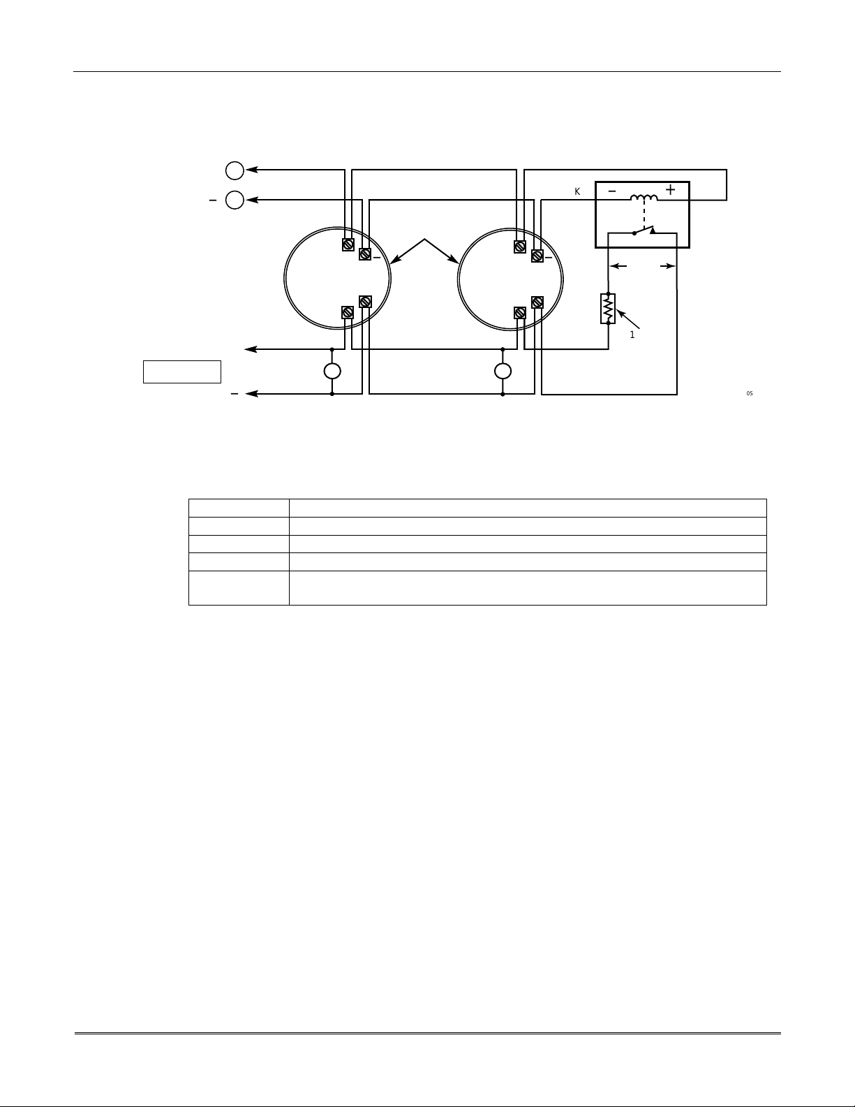
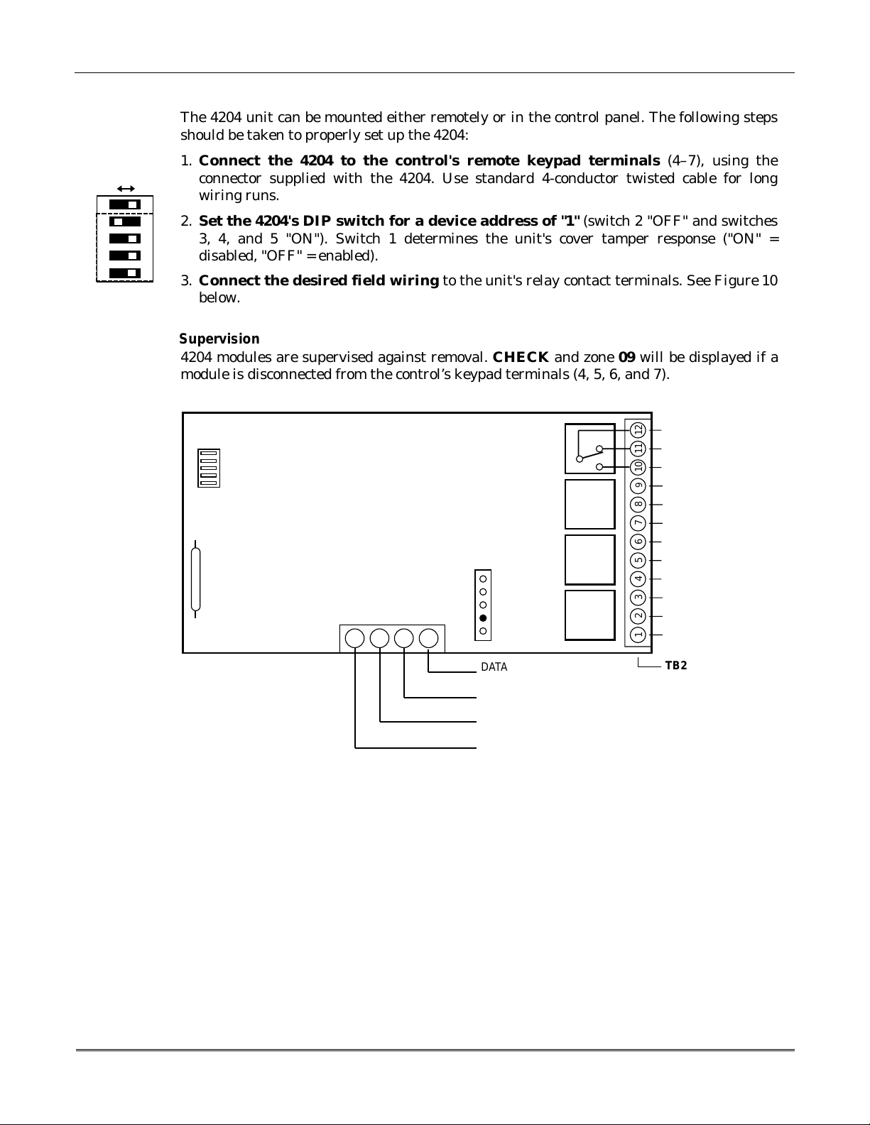
4204 Setup
The 4204 unit can be mounted e ither remote ly or in the control p anel. The follo wing ste ps
should be taken to properly set up the 4204:
1. Connect the 4204 to the control's remote keypad terminals (4–7), using the
connector supplied with the 4204. Use standard 4-conductor twisted cable for long
wiring runs.
2. Set the 4204's DIP switch for a device address of "1" (switch 2 "OFF" and switches
3, 4, and 5 "ON"). Switch 1 determines the unit's cover tamper response ("ON" =
disabled, "OFF" = enabled).
3. Con nect the des ired fie ld wiri ng to th e unit's r elay c ontact te rmin als. See Figure 10
below.
Supervision
4204 modules are supervised against removal. CHECK and zon e 09 will be displayed if a
module is disconnected from the control’s keypad terminals (4, 5, 6, and 7).
4204
DIP SWITCH
FOR SETTING DEVICE ADDRESS
AND ENABLING/DISABLING TAMPER
COVER T AMPER (REED) SWITCH
Programming Options
RELAY
4
TYPICAL
(SHOWN "OFF")
4-PIN KEYPAD PLUG
EITHER OR BOTH
CAN BE USED
TB1
13 14 15 16
YEL
BLK
GRN
RED
Figure 10. 4204 Connections to Control
DATA I N
FROM CONTROL
(–) GROUND
DATA OUT
TO CONTROL
(+) 12V
RELAY
3
RELAY
2
RELAY
1
C
121110
NC
NO
9
C
87654321
NC
NO
C
NC
NC
NO
C
NC
NO
TB2
V10SE-016-V0
6-2
In the VISTA-10SE, each device must be programmed as to how to act (ACTION), when to
activate (START), a n d when to de-activate (STOP). Refer to t he programming procedures for
✱
80 and
✱
81 interactive modes that are provided in the MECHANICS of PROGRAMMING,
OUTPUT DEVICE PROGRAMMING, and ZONE LISTS sections for specific programming
details.

SECTION 7
4285 and 4286 VIP Module
••••••••••••••••••••••••••••••••••••••••••••••••••
In This Section
Installing the VIP Module
♦
Programming the 4285/4286 VIP Module
♦
••••••••••••••••••••••••••••••••••••••••••••••••••
Checking 4285/4286 VIP Module Operation
♦
Installing the (Voice Interactive Phone) Module
General Information
The 4285/4286 VIP Module is an add-on accessory for the VISTA–10SE that permits access to
the security system via a TouchTone phone (either on premises or by a call-in when away).
The VIP Module can announce many of the same words that would normally be displayed on
an alpha keypad under the same system conditions.
When using the VIP Module, addressable keypads must be used in the system, but set to the
non-addressable mode (address 31); i.e., do not use a 6127 keypad.
When properly connected, the VIP Module will enable the user to do the following via a
TouchTone telephone:
•
Receive synthesized voice messages over the phone regarding the status of the security
system.
•
Arm and disarm the security system and perform most other commands using the
telephone keypad, with voice annunciation provided over the phone as confirmation after
a command is entered.
The phone used f or p ho ne acce ss must h ave To uc hTo ne capability , tho u gh Tou ch Ton e se rv ice
is not necessary (if premises uses PULSE dialing, switchable phones must be set for
TouchTone temporarily before attempting phone access).
A Pho ne Access User's Guide for phone access to the security system is provided with the
VIP Module for the user of the system.
U
L
Mounting the VIP Module
The VIP Module is not Listed for UL installation use
The VIP Module may be mou nted in the control cabine t if space is available or, if th is is not
possible, on the side of the cabinet or adjacent to it.
When mounting the VIP Module outside the cabinet, use the screw holes at its rear. That will
permit it to be mounted horizontally or vertically (double-sided tape may be used, if
preferred). Wires can be bro ug ht o ut f ro m th e sid e or back (a ro un d bre ako ut is also available
on the back).
Affix the VIP Module’s connections label (supplied separately) to the inside of the VIP
Module's cover if the cover is used. If yo u have installed th e module within the cabinet, affix
the label to the ins ide of the control cabinet's door.
.
7–1

VISTA-10SE Installation and Setup Guide
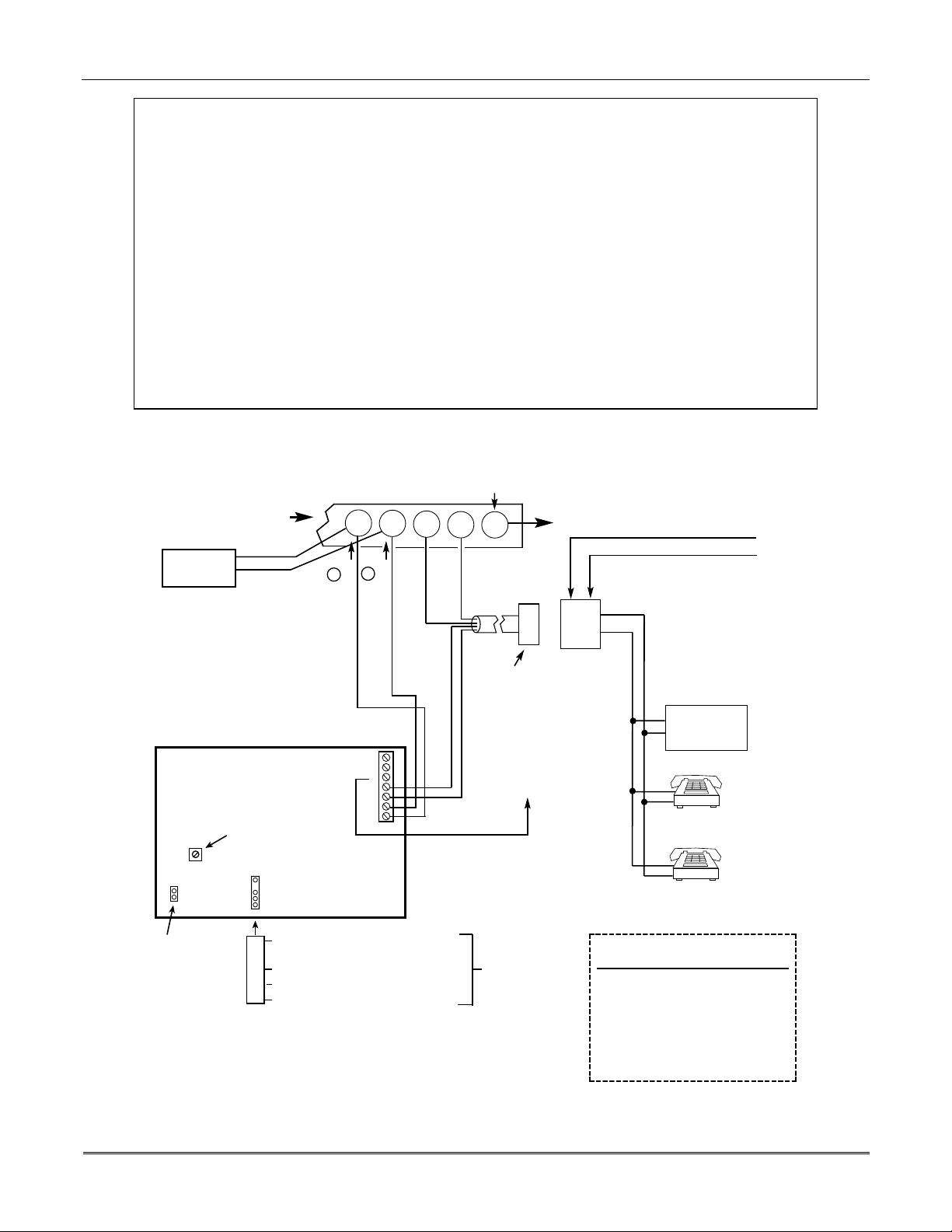
VIP Module Wiring
The VIP Module is wired between the control panel and the premises handset(s). It listens
for touch-tones on the phone line and reports them to the control panel. During on-premises
phone access, it powers the premises phones; during off-premises phone access, it seizes the
line from the premises phones and any answering machines.
NOTE: The phone lines must be in service for the VIP Module to function, even when
accessing the system from an on-premises phone.
1. Make 12V (+) an d (–) and data in and data out connections from the VIP Module to the
control, using the connector cable supplied with the VIP Modul e (see Figure 10).
Color Lead Terminal On Control
GREEN DATA IN (terminal 6)
BLACK AUX – (terminal 4)
RED AUX + (terminal 5)
YELLOW DATA OUT (terminal 7)
2. Insert the keyed connector at the other end of the connector cable into the mating header
on the VIP Module (see diagram on next page for location of the header).
*
*
These are the same connections
as those used for remote
keypads
.
3. Conne ct terminals 1 through 4 on the VIP Module as shown in the Wiring Table and in
the 4285/4286 wiring diagram that follows.
Use an RJ31X jack with a direct-connect cord and make all connections exactly as shown. If
the leads on the direct-connect cord are too short to reach their assigned terminals, splice
additional wires to them, as required.
4285/4286 WIRING TABLE
4285/4286/4286
Terminal
Phone In (Tip)
1.
Phone In (Ring)
2.
Phone Out (Tip)
3.
Phone Out (Ring)
4.
NOT USED
5.
Output High
6.
Output Rtn
7.
If no touch-tones are produced following access to the security system
Connects to:
Terminal (17) on control.
Terminal (18) on control.
BROWN lead from direct-connect cord.
GRAY lead from direct-connect cord.
——
Not used (4285). Spkr High on 4286.
Not used (4285). Spkr Return on 4286.
from on-premises
(this
problem may arise in rare cases), it may be necessary to reverse the wires connected to
terminals 3 and 4 on the VIP Module
control.
Figure 11
shows the wiring connections that will provide proper operation in most
and
the wires connected to terminals (17) and (18) on the
cases.
7-2
Caller ID Units
If the telephone system on the premises includes a Caller ID unit, connect the ID unit
directly to the “Handset” terminals (17 and 18) on the control, as shown in Figure 11.
Section 7 - 4285/4286 VIP Module
4285/4286 VIP Module WIRING NOTES:
1.
Wire the VIP Module exactly as shown, using a direct-connect cord and RJ31X jack.
2.
If you do no hear tones when pressing keys after accessing the security system via an on-premises
phone, try reversing the pair of wires connected to terminals 3 and 4 on the VIP Module
pair of wires connected to terminals 17 and 18 on the control.
3. If you hear an error signal (fast busy signal) when trying to access the system via the phone, check
for correct line se izure wiring, as described in note 4.
4. Connection to the incoming telco line via a RJ31X jack and direct-connect cord, as shown in this
diagram, is essential, even if the system is not connected to a central station.
The 4285 or 4286
will not function if this is not done.
The house phone lines (gray and brown wires) must be wired to the VIP Module
terminals, not to the control terminals. Otherwise, an error signal (fast busy signal) will
occur when you try to access the system from an on-premises phone.
5. If the telephone system on the premises includes a Caller ID unit, connect the unit
“Handset” terminals (17 and 18) on the control, as shown.
and
directly
the
to the
TERMINALS
ON CONTROL
CALLER ID
UNIT
IMPORTANT NOTE FOR
EXISTING INSTALLATIONS:
EXISTING WIRES
CONNECTED TO THE
"HANDSET" TERMINALS ON
CONTROL MUST BE MOVED
FROM THERE TO TERMINALS
3 AND 4 ON THE 4285.
4285/4286
VIP MODULE
SPEAKER VOLUME
ADJUSTABLE ON
4286 ONLY
KEYED
HEADER
UNUSED
CONNECTOR
WITH FLYING
LEADS
YELLOW: TO DATA OUT (term. 7)
NO CONNECTION
RED: TO AUX (+) (term. 5)
BLACK: TO AUX. GROUND (–) (term.4)
GREEN:
Handset
{
17
1
MUST CONNECT TO
ON 4285 (TIP)
TO DATA IN (term. 6)
Incoming
Teleco Line
{
19
18
2
GREEN (TIP)
ON 4285 (RING)
MUST CONNECT TO
12345 6 7
20
21
DIRECT
CONNECT
CORD
RED (RING)
PLUG
GREY (R)
BROWN (T)
CONNECTION
TO CONTROL
PANEL
TERMINALS
USED FOR
KEYPAD
CONNECTIONS
GROUND
NO
TO EARTH GROUND (COLD WATER PIPE, ETC.)
INCOMING TELCO LINE
TIP
RING
TIP
RJ31X
RING
JACK
CA38A
IN
CANADA
PREMISES ANSWERING
MACHINE AND PHONES
ANSWERING
MACHINE
*
*
*
NOTE: IF THE TELEPHONE HAS BUILT-IN CALLER ID,
THE CALLER ID FUNCTION MAY NOT WORK
TERMINAL ASSIGNMENTS
1 - TIP
2 - RING
3 - TIP
4 - RING
5 - NO CONNECTION
6 -
}
7 -
4285/4286
PHONE INPUT
}
PHONE OUTPUT
}
AUDIO OUT
4286 ONLY
V10SE-029-V0
.
Figure 11. 4285/4286 VIP Module Wiring Connections
7-3

VISTA-10SE Installation and Setup Guide
Programming the Control for Phone Access
To program the control for phone access using the 4285/4286 VIP Module, you must assign a
✱
VIP Module access code (
26) and ring detection count (✱95). Also, you may optionally select
words and/or form custom words that would be displayed on the keypad. Refer to THE DATA
FIELD DESCRIPTION and ALPHA DESCRIPTOR PROGRAMMING sections for specific
programming details.
Perform a preliminary check of the VIP Module, as indicated next.
Checking the Operation of the VIP Module
To Check VIP Module Operation From an On-Premises Phone
1. Pick up the phone and enter the programmed 2-digit VIP Module access code.
Annunciation of a system status report should automatically start. See the User Guide
accompanying the VIP Module for detailed information regarding the nature of the status
report, if necessary.
2. During any pause in the status report, or immediately following it, key the following via
the keypad on the phone:
4111 (Installer code) + 1 (OFF).
You should hear a beep on the phone and from a wired keypad. You should als o hear the
words, "Disarmed...Ready to Arm" or "Disarmed...Not Ready to Arm," indicating that
the command was entered successfully. (The voice message, "Disarmed...Not Ready to
Arm" indicates an open zone).
3. Hang up the phone.
To Check VIP Module Operation from an Off-Premises Phone:
1. Have someone dial the premises phone number, using a TouchTone phone.
•
If the phone system does not include an answ ering machine, the caller hears 2 long
tones, followed by a voice prompt "
HELLO, ENTER PHONE CODE NOW
must enter the programmed 2-digit phone code (entered in field
MODULE ACCESS CODE)
•
If the premises phone system includes an answering machine, the 2-digit phone
.
code must be entered during a pause at the beginning of, or during, the outgoing
answering machine message. Then the caller hears a voice prompt asking for entry of
the 4-digit system code ( "
ENTER SYSTEM CODE NOW
2. The caller sh ould then enter the Installer Code ( 4111). As a safety feature , there is a 3-
try limit in which to enter each code (phone code and system code), after which time the
call-in is aborted. Also, if no keys are pressed for a period of 20 seconds, the call-in is
aborted.
Annunciation of a system status report will start if both codes were entered correctly.
3. During an y pause in the statu s report, or imme diately follo wing it, the caller sh ould key
the following via the keypad on the phone:
Installer Code (4111), then 1 (OFF).
The caller should hear a beep from the phone and a wired keypad on the premises. The
caller should also hear the words "Disarmed...Ready to Arm" or "Disarmed...Not
Ready to Arm" on the phone, indicating that the command was entered successfully.
"Disarmed...Not Ready to Arm" would indicate an open zone.
4. At this point, the caller can hang up the phone.
5. Verify with the caller that there was successful access to the system and that the
appropriate voice announcements were hea rd over the phone.
").
" The caller
.
✱
28,
PHONE)
7-4
6. If the VIP Module functioned satisfactorily, unplug the AC transformer from the AC
outlet.
 Loading...