

Vista ES-150 Installation And Operator's Manual

ES-150
12V SERIES
Transformers
INSTALLATION & OPERATORS GUIDE
Made in the U.S.A.
FEATURES AND CONTROLS 2
MOUNTING INSTRUCTIONS 2
TRANSFORMER SIZING 2
LOW VOLTAGE CABLE LENGTH 2
LOW VOLTAGE CABLE LAYOUT OPTIONS 3
CABLE CONNECTION DETAIL 3
OUTPUT ADJUSTMENT SWITCH 3
UL 1838
REMOTE PHOTOCELL CONTROL FUNCTIONS FOR
RP MODULE
TC-112 TIMER SETTING PROCEDURE 4
DTC-170 DIGITAL TIMER SETTING PROCEDURE 4
TIMER REMOVAL AND REPLACEMENT 4
TIMER SETTING WITH FIELD INSTALLED
PHOTOCELL
ELECTRONIC TIMER AND REMOTE PHOTOCELL 4
ADJUSTABLE CABLE RACEWAY FEEDER (ACRF) 4
3
4
MULTI-TAP INSTALLATION 3
Vista Professional Outdoor Lighting reserves the right to modify the design and/or construction of the transformer shown without further notication.
1625 Surveyor Avenue • Simi Valley, CA 93063 • (805) 527-0987 • (800) 766-VISTA (8478)
FAX: (888) 670-VISTA (8478) • email@vistapro.com • www.vistapro.com
TROUBLESHOOTING CHECKLIST 4
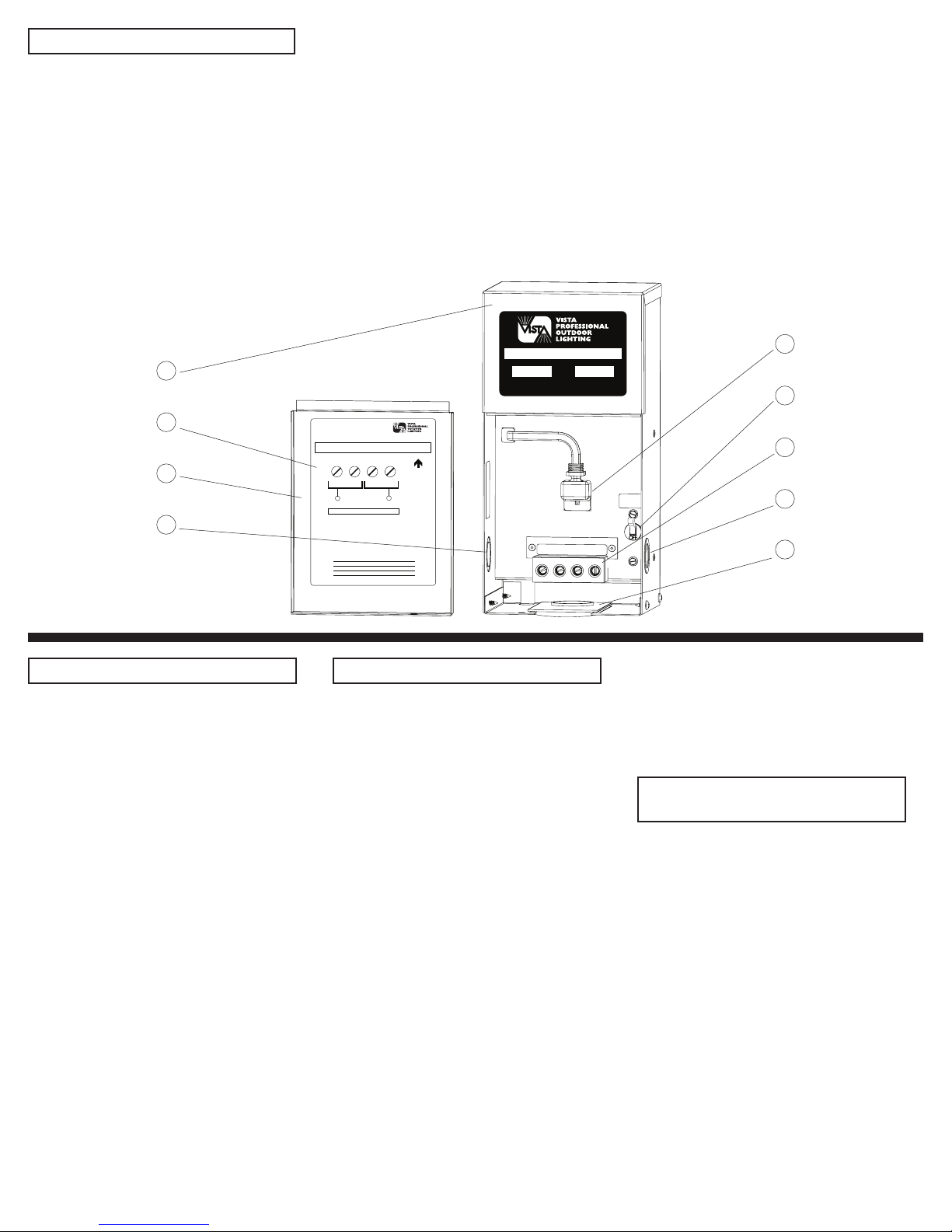
FEATURES AND CONTROLS
POWER TRANSFORMER
ES-150
VISTA PROFESSIONAL OUTDOOR LIGHTING
1625 Surveyor Ave, Simi Valley, CA 93063
ES-150
Low Voltage Landscape Lighting Transformer
Input: 120V 50/60HZ 1.49A Output: 12VAC & 15VAC, 150W
This transformer is equipped with an output circuit protector. Refer to “Caution”
section below on this label.
THIS END UP
MADE IN USA
TRANSFORMER WIRING
OUTPUT TERMINALS
COM
COM 12V
15V
DO NOT EXCEED 150 WATTS
MAXIMUM LOAD
LAMP LOAD
ATTENTION: READ SAFETY INSERT FIRST
INSTALLATION
1. Mount this unit at least 12 inches above deck or ground level. This transformer is suitable for
indoor or outdoor installation using an input line cord or permanent class 1 conduit wiring. The
best installation has the transformer centrally located ... as close as possible to the furthest fixture.
2. Calculate total lamp wattage and add 10%. The result should not exceed rated transformer
output. Do not overload.
3. Refer to diagram above. Connect fixtures in parallel using 12 gauge or larger direct burial cable.
Strip ½” of cable insultation and twist wire strands tightly before insertion into output connector.
Connector will accept one #6, two #8, three #10 or four #12 wires per position. Tighten connector
screws firmly. Re-tighten after one week of operation.
4. Circuit Protector:
A. The circuit protector will trip if cable is shorted or if total of lamps exceed 150W.
B. To reset protector - move lever to ON.
C. If protector trips again, check for overload or short circuit.
CAUTION: If lamps go off during an on cycle, the circuit protector is sensing an overoad.
Transformer output (lead) should be checked by a qualified service person.
RUN 1.
RUN 2.
RUN 3
RUN 4.
SUITABLE FOR INDOOR OR OUTDOOR USE
CIRCUIT
PROTECTOR
ON TO RESET
Stainless Steel Cabinet1.
20 gauge, top grade, polished & clear-coat nish.
Operating Instructions inside door.2.
Refer to these instructions for additional information on wiring to
the transformer.
Removable Front Panel3.
The door can be removed for greater access to wiring
compartment during installation.
½” - ¾” Knockouts4.
For conduit and accessory mounting.
1
2
3
4
120-volt accessory receptacle5.
For use with optional, removable multi-setting mechanical (TC-
112) 24-hour timer or electronic/digital (DTC-150) 7-day timer (with
battery backup).
Circuit Protector6.
Move lever to “ON” to reset.
Terminal Strip7.
Dual voltage taps, 12 volts and 15 volts.
Adjustable Cable Raceway Feeder (ACRF)8.
Vista Exclusive - Easiest in the industry to wire: adjustable cable
raceway feeder easily accommodates multiple wire runs. Or use
handy 1¾” conduit knockout.
5
6
7
4
9
MOUNTING INSTRUCTIONS
WARNING: Transformers must be installed
in accordance with the National Electrical
Code (NEC) and local codes. Failure to
do so will void the warranty and may result
in serious injury and/or damage to the
transformer.
1. Find a suitable, flat-surfaced location
to mount transformer, taking in to
consideration proximity to 120 volt AC
power source.
2. Attach provided template to wall at
desired height. (Should be mounted at
least 1.5’ from the ground for safe and
convenient operation.)
3. Center punch and drill (with an
appropriate bit size for the screws to be
used) at crosshair marks on the template.
4. Using appropriate screws for the
selected mounting surface, insert screws
into predrilled holes deep enough to slip
transformer keyhole slots over. (Make sure
screws are of a load bearing quality.)
5. Hang transformer case securely over
screws.
TRANSFORMER SIZING
Low voltage lighting systems require
the use of a transformer to reduce the
standard 120 volt power from ordinary
household electricity to the 12 volt needed
to power low voltage lamps. Transformers
vary in size or capacity. The total lamp
wattage (load) of all fixtures connected
to one transformer must not exceed the
wattage capacity of the transformer.
Therefore, to determine the transformer
size needed, simply add up the wattage
of all lamps you plan to use +10% for cable
& connection factor. (Low voltage cable
and fixture connections add hidden watts
to your system.)
TRANSFORMER SIZE = TOTAL FIXTURE WATTS
x 1.1
TIP: All low voltage connections must be
tight and waterproof.
Select a transformer that matches
as closely as possible your total lamp
wattage. For example: if you have 12
fixtures all rated at 10 watts, you will need
a 150-watt transformer (12 x 10 = 120 watts
plus 10% = 132). If your total wattage is
too great, either divide the total load
between two transformers or use a more
powerful model. Selecting a transformer
with about 20% higher capacity than your
total lamp wattage will allow for adding a
fixture or two later.
LOW VOLTAGE CABLE
LENGTH
In planning a low voltage system, it is
necessary to consider the impact of
voltage drop. Because of cable’s inherent
resistance, voltage drops along its length:
the end-of-run lamps will be dimmer than
those at the beginning. Since voltage drop
is a function of cable length and cable
size and total fixture wattage, voltage
drop can be minimized in several different
ways:
• Use multiple cable runs
• Use heavier gauge cable (8 or 10
gauge)
• Shorten cable lengths or runs
• Reduce wattage of individual fixtures
• Reduce the total number of fixtures on
a run
• Use multiple transformers in different
locations
 Loading...