

Page 1
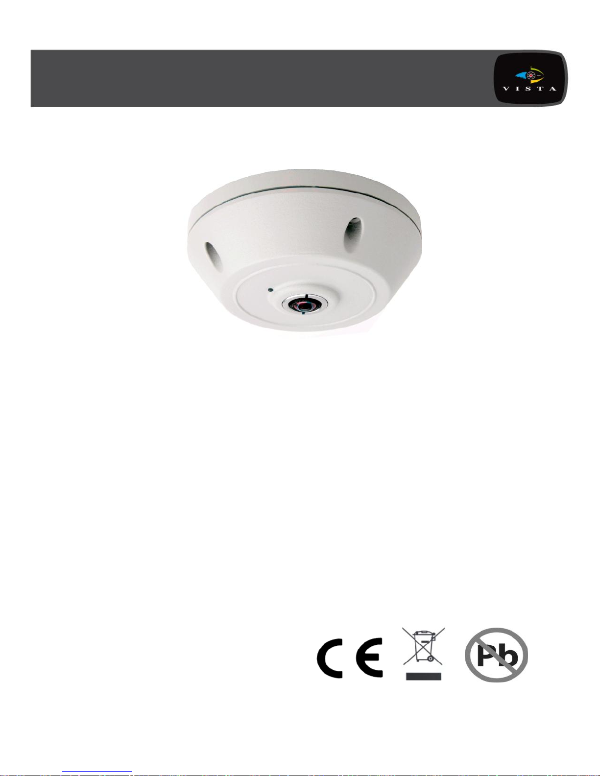
Set up and user manual for
the Eclipse2 camera
Eclipse
2
Manual
Page 2

Page 3
Before You Begin
Read these instructions before installing or operating this product.
Note: This installation should be made by a qualified service person and should
conform to local codes.
This manual provides installation and operation information. To use this document, you
must have the following minimum qualifications:
A basic knowledge of CCTV systems and components
A basic knowledge of electrical wiring and low-voltage electrical connections
Intended use
Only use this product for its designated purpose; refer to the product specification and
user documentation.
Customer Support
For assistance in installing, operating, maintaining and troubleshooting this product refer
to this document and any other documentation provided. If you still have questions,
please contact Norbain Technical Support and Sales:
Norbain Ltd, 210 Wharfedale Road, IQ Winnersh, Wokingham, Berkshire RG41 5TP,
England.
UK: +44 (0) 118 912 5000
Netherland: +31 (0) 76 579 2577
Belgium: +32 (0) 3 369 8080
South Africa: +27 (0) 11 887 1546
Portugal: +351 234 301900
Spain: +34 91 503 06 78
Middle East: +971 4 881 14332
Rest of World: +44 118 912 5000
Note: You should be at the equipment and ready with details before calling Technical
Support.
Conventions Used in this Manual
Boldface or button icons highlight command entries. The following WARNING,
CAUTION and Note statements identify potential hazards that can occur if the
equipment is not handled properly:
* WARNING:
Improper use of this equipment can cause severe bodily injury or
equipment damage.
Page 4

** Caution:
Improper use of this equipment can cause equipment damage.
Note: Notes contain important information about a product or procedure.
RoHS Announcement
All lead-free products offered by the company comply with the
requirements of the European law on the Restriction of Hazardous
Substances (RoHS) directive, which means our manufacture
processes and products are strictly “lead-free” and without the
hazardous substances cited in the directive.
The crossed-out wheeled bin mark symbolizes that within the
European Union the product must be collected separately at the
product end-of-life. This applies to your product and any peripherals
marked with this symbol. Do not dispose of these products as
unsorted municipal waste.
CE Mark
This apparatus is manufactured to comply with the radio interference.
A Declaration of Conformity in accordance with the following EU
standards has been made. The manufacturer declares that the
product supplied with this document is compliant the provisions of the
EMC Directive 2004/108/ EC, the CE Marking Directive 93/68 EEC and
all associated amendments.
* This symbol indicates electrical warnings and cautions.
** This symbol indicates general warnings and cautions.
NORBAIN LTD reserves the right to make changes to the product and specification of
the product from time to time without prior notice.
Page 5
WARNINGS AND CAUTIONS:
To reduce the risk of fire or electric shock, do not insert any metallic objects through the
ventilation grills or other openings on the equipment.
IMPORTANT SAFEGUARDS
1. READ AND RETAIN INSTRUCTIONS
Read the instruction manual before operating the equipment.
Retain the manual for future reference.
2. CLEANING
Turn the unit off and unplug from the power outlet before cleaning. Use a damp
cloth for cleaning. Do not use harsh cleansers or aerosol cleaners.
3. ATTACHMENTS
Do not use attachments unless recommended by manufactured as they may affect
the functionality of the unit and result in the risk of fire, electric shock or injury.
4. MOISTURE
Do not use equipment near water or other liquids.
5. ACCESSORIES
Equipment should be installed in a safe, stable location. Any wall or shelf mounting
accessory equipment should be installed using the manufacture's Instructions. Care
should be used when moving heavy equipment. Quick stops, excessive force, and
uneven surfaces may cause the equipment to fall causing serious injury to persons
and objects.
6. VENTILATION
Openings in the equipment, if any, are provided for ventilation to ensure reliable
operation of the unit and to protect if from overheating. These openings must not be
blocked or covered
7. POWER SOURCES
The equipment should be operated only from the type of power source indicated on
the marking label. If you are not sure of the type of power supplied at the installation
location, contact your dealer. For equipment designed to operate from battery
power, refer to the operating instructions.
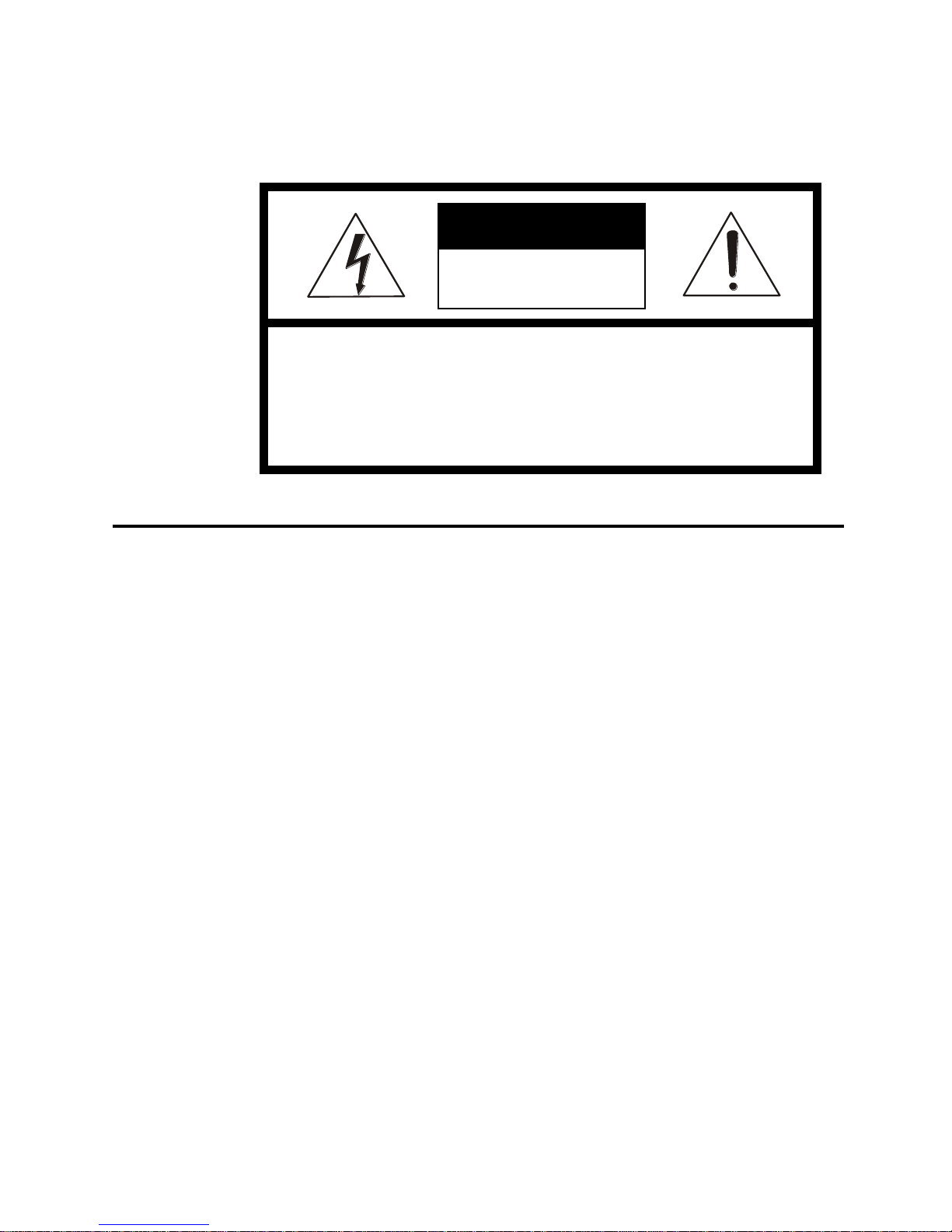
WARNING: TO REDUCE THE RISK OF ELECTRIC SHOCK,
DO NOT REMOVE COVER (OR BACK).
NO USER-SERVICABLE PARTS INSIDE.
REFER SERVICING TO QUALIFIED SERVICE PERSONNEL.
CAUTION
RISK OF ELECTRIC SHOCK
DO NOT OPEN
CAUTION
Page 6

8. GROUNDING OR POLARIZATION
Equipment that is powered through a polarized plug (a plug with one blade wider
than the other) will fit into the power outlet only one way. This is a safety feature. If
you are unable to insert the plug fully into the outlet, try reversing the plug. Do not
defeat the safety purpose of the polarized plug.
Alternate Warning: If the equipment is powered through a three-way groundingtype plug, a plug having a third (grounding) pin, the plug will only fit into a groundingtype power outlet. This is a safety feature. Do not defeat the safety purpose of the
grounding-type plug.
If your outlet does not have the grounding plug receptacle, contact your local
electrician.
9. CORD AND CABLE PROTECTION
Route power cords and cables in a manner so to protect them from damage by
being walked on or pinched by items places upon or against them.
10. LIGHTNING
For protection of the equipment during a lightning storm or when it is left unattended
and unused for long periods of time, unplug the unit from the wall outlet. Disconnect
any antennas or cable systems that may be connected to the equipment.
This will prevent damage to the equipment due to Lightning or power-line surges.
11. OVERLOADING
Do not overload wall outlets and extension cords as this can result in a risk of fire or
electric shock.
12. SERVICING
Do not attempt to service the video monitor or equipment yourself as opening or
removing covers may expose you to dangerous voltage or other hazards.
Refer all servicing to qualified service personnel.
13. DAMAGE REQUIRING SERVICE
Unplug the equipment from the wall outlet and refer servicing to qualified service
personnel under the Following conditions:
A. When the power supply cord or the plug has been damaged.
B. If liquid has spilled or objects have fallen into the Unit.
C. If the equipment has been exposed to water or other liquids.
D. If the equipment does not operate normally by following the operating
instructions, adjust those controls that are covered by the operating instructions as
Improper adjustment for other controls may result in damage to the unit.
E. If the equipment has been dropped or the casing is damaged.
F. When the equipment exhibits a distinct change in performance.
14. REPLACEMENT PARTS
When replacement parts are required, be sure the service technician uses
replacement parts specified by the manufacturer or that have the same
characteristics as the original part.
Unauthorized substitutions may result in fire, electric shock, or other hazards.
15. SAFETY CHECK
Upon completion of any service or repairs to the equipment, ask the service
technician to perform safety checks to verify that the equipment is in proper
operating condition.
16. FIELD INSTALLATION
The installation of equipment should be made by a qualified service person and
should conform to all local codes.
Page 7

17. CAUTION - THESE SERVICING
INSTRUCTIONS ARE FOR USE BY QUALIFIED SERVICE PERSONNEL ONLY.
TO REDUCE THE RISK OF ELECTRIC SHOCK DO NOT PERFORM ANY
SERVICING OTHER THAN THAT CONTAINED IN THE OPERATING
INSTRUCTIONS UNLESS YOU ARE QUALIFIED TO DO SO.
18. Use certified/Listed Class 2 power supply transformer only
TABLE OF CONTENTS
INTRODUCTION ------------------------------------------------------------------------------------- --1
MINIMUM PC/LAPTOP SPEC ------------------------------------------------------------------- --- 1
INSTALLATION & CONNECTION --------------------------------------------------------------- --2
CONNECTING TO THE ECLIPSE
2
--------------------------------------------------------------- 4
NETWORK SETTINGS ------------------------------------------------------------------------------- 5
CAMERA SET UP -------------------------------------------------------------------------------------- 7
SPECIFICATION --------------------------------------------------------------------------------------- 16
LINE DRAWING ---------------------------------------------------------------------------------------- 18
FACTORY DEFAULT --------------------------------------------------------------------------------- 18
CAMERA STREAMS ---------------------------------------------------------------------------------- 19
Page 8

INTRODUCTION
Features:
• 1 / 2.5" 5MP CMOS
• 1850 x 3600 field of view lens
• 2144 x 1944 max resolution @12.5 ips
• Colour / monochrome operation
• MJPEG, H.264 or MPEG-4 encoding
• Constant and Variable Bitrate options
• 14 panoramic and ePTZ streams
• De-warping is done within camera
• Accessible via internet browsers (PC/laptop required)
• 10 dynamic privacy zones
• Up to 20 users with selectable access levels
• Ceiling, Wall or Table orientation
• PoE or 12-24VDC operation (6W)
• Compact dimensions: 147.5 Ø x 54 (H) mm
• Multi language support: English, Russian, German, French,
Spanish, Italian, Dutch & Portuguese
MINIMUM PC / LAPTOP SPEC
Recommended minimum specification:
OS: Windows 7 Professional
CPU: Intel i3 Dual Core, 2Ghz or above
Display: 1024 x 768, 256MB supporting DirectX 11
RAM: 3GB
HDD: 20MB for installation
Browser: Internet Explorer 9
Mozilla Firefox 6
Safari 5
Chrome 17
Page 9
INSTALLATION & CONNECTION
Overview:
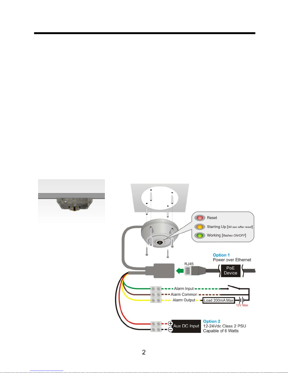
The Eclipse2 camera is 5MP 3600 with panoramic and de-warped IP
video streams, designed to be integrated via SDK and API into Video
Management Systems (VMS). This manual enables basic set up of the
camera via to view the live streams via web browser.
The Eclipse2 is a sealed camera with no internal moving parts and
designed to be surface mounted either on a wall, ceiling or table / floor.
Using the provided screws or others to suit the mounting location,
ensuring the camera is securely fitted. If the Eclipse 2 is wall mounted,
putting the status LED in the ‘12 o’clock’ position will ensure the camera
is the correct way up.
Fig1. Cross section of Fig2. Example of typical mounting and wiring
Surface-mount installation
Page 10
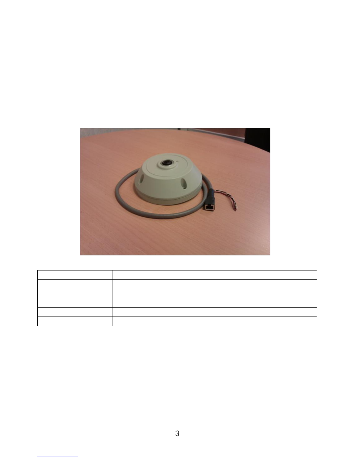
The camera is provided with a “flying” lead which contains all of the
required connections. Both data and power connections to the camera
are provided using a single cable with a RJ45 socket. The camera uses
Power over Ethernet (PoE) but can also be powered by 12-24VDC
using the additional red and black wires in the lead. PoE supply should
be provided by equipment compliant with IEEE 802.3AF.
In addition to the RJ45 and power cores there are also the alarm in,
alarm out and common wires.
Wire
Description
Red
12-24VDC
Black
0V
Green*
Alarm Input
Yellow**
Alarm Output
Brown
Alarm Common
*Orange on some models
** White on some models
Page 11
CONNECTING TO THE ECLIPSE
2
The Eclipse2 is defaulted with DHCP enabled. If no DHCP server is
present on the network, the camera will use the default IP address of
192.168.1.100. To communicate with the camera, a suitable PC or
laptop computer is required (see minimum PC spec on page 1), which
has been enabled to use the appropriate subnet, together with a
browser such as Firefox or Internet Explorer.
On the browser address bar, simply type in the IP address of the
camera. A username and password will be required to access the
camera, by default these are:-
Username: Admin
Password: Admin
Or:
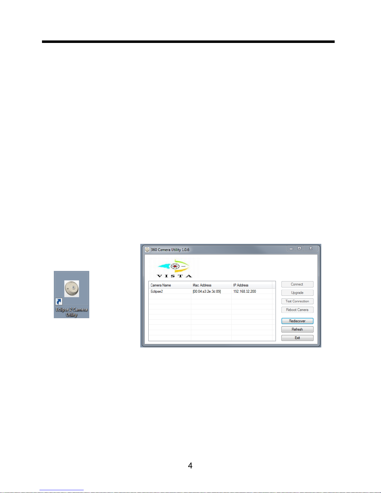
Load the Eclipse2 utility from the disc onto your PC / Laptop:
1. Run the program
2. Click the ‘Rediscover’ button
3. Highlight the Eclipse2 you wish to connect to
4. Click ‘Connect’
5. Your PC / Laptop default web browser will then connect
Page 12
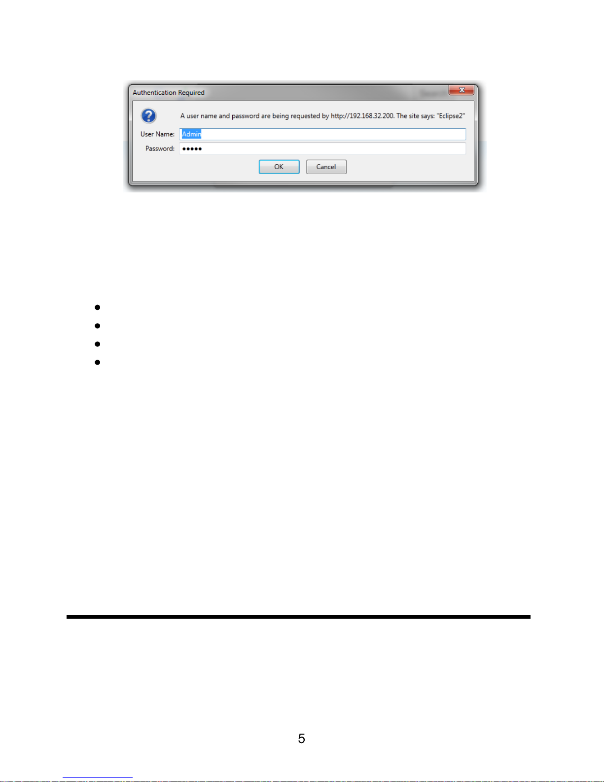
User Name: Admin / Password: Admin
Eclipse2 has been tested with the following browsers (other web
browsers may work but have not been tested and may not have all
functionality):
Internet Explorer 9
Mozilla Firefox 6
Safari 5
Chrome 17
Notes on IE (Internet Explorer):
1) An additional step is required to install the java applet required
to display the MJPEG streams. Java runtime environment is
required for this and must be installed separately, if this is not
already present on the PC / Laptop. Once this is installed and
the webpage refreshed, you will be prompted to install the java
applet).
2) ePTZ control (UP / DOWN / LEFT / RIGHT / ZOOM) of the
camera will require you to use the PTZ / Zoom buttons on the
camera web page and you will not be able to click on the image
to ePTZ / zoom.
NETWORK SETTINGS
Once connected to the Eclipse2, navigate to the Network page.
Change network settings as required:
Page 13
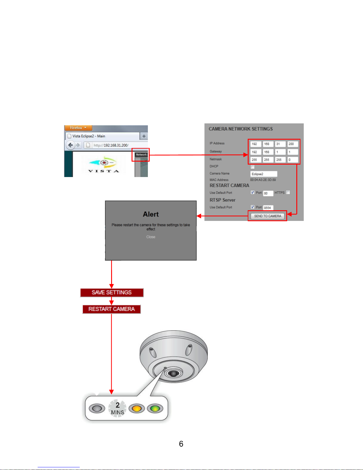
1. Change IP settings to suit
2. Click the ‘SEND TO CAMERA’ button
3. Warning comes telling you restart camera (close this)
4. Click ‘SAVE SETTINGS’ button
5. Click ‘RESTART CAMERA’ button
6. The camera will then restart after approx 2mins
7. Reconnect using the new IP address
Fig3. IP address change schematic
Page 14
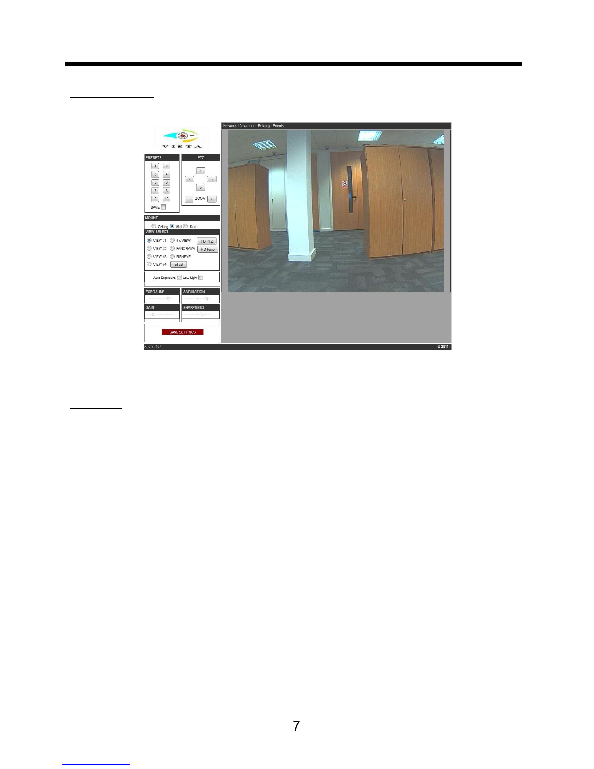
CAMERA SET UP
Main screen
Presets
There are 10 presets available that can be used with the following dewarped streams:
VIEW#1 / VIEW#2 / VIEW#3 / VIEW#4 / 4 x VIEW (quad)
To set a preset
1. Tick the save box
2. ePTZ to the required point
3. Click on the preset button (1 to10) that you wish to save
4. Untick the save box
5. Preset is now saved
Page 15
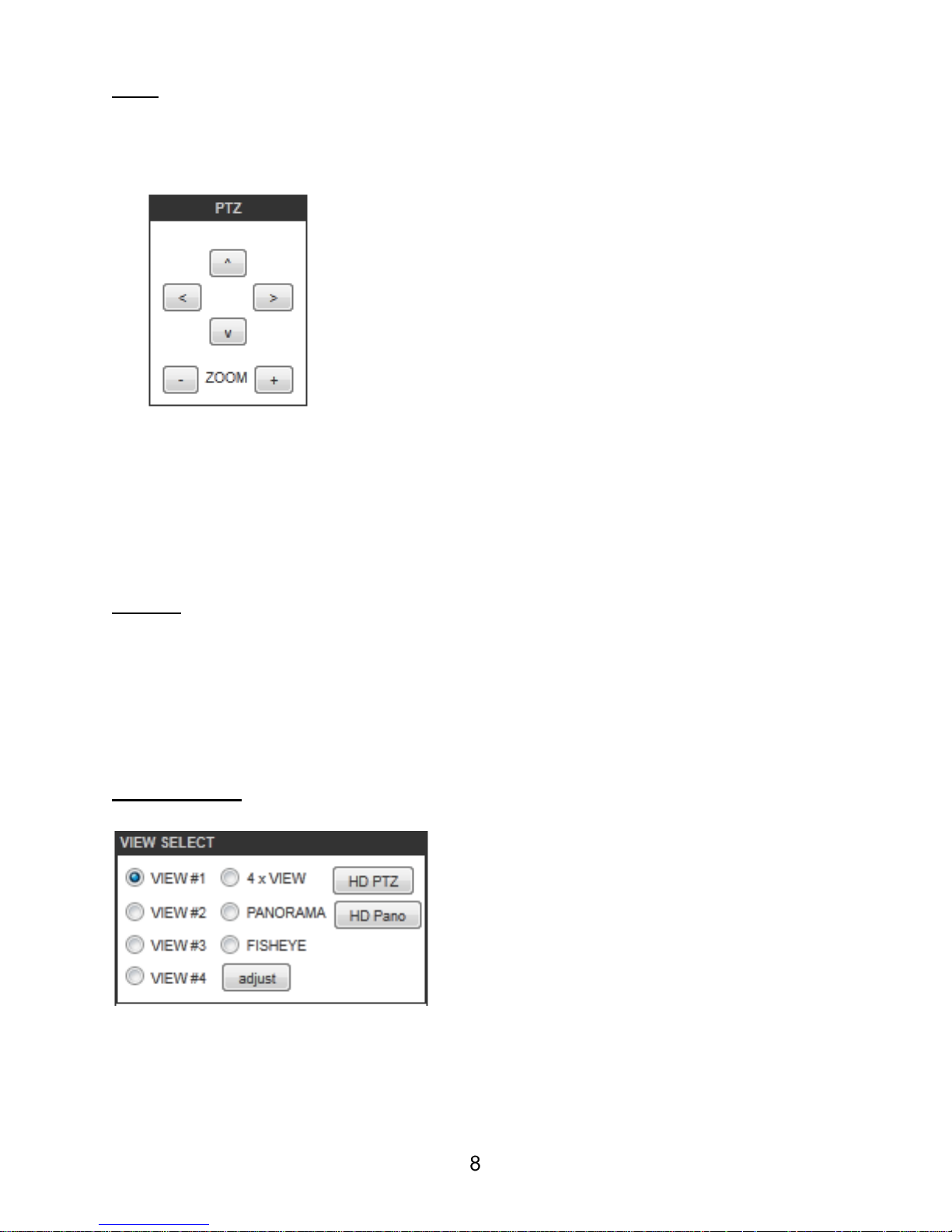
PTZ
With all views (except FISHEYE) there is the ability to ePTZ the image.
This can be achieved with the UP / DOWN / LEFT / RIGHT & ZOOM + /
- buttons:
Please note that in internet explorer (IE), this is the only way to ePTZ
the selected view. With other browsers (e.g. Firefox), ePTZ can be
achieved by holding the mouse cursor on the displayed image and left
clicking the mouse to navigate around the image, the scroll wheel acts
as the zoom in / out function.
Mount
Ceiling / Wall / Table
This orientates both the image and ePTZ functionality (if wall mounted
ensure the LED is in the 12 o’clock position as this will have the image
the correct way up).
View Select
This allows live viewing of the selected stream
Page 16

Name
Resolution
Type
View 1 - 4
640 x 480
De-warped ePTZ
4 x view (quad)
320 x 240
(per section)
De-warped ePTZ
Panorama
640 x 480
1800 panorama (tilt function only)
Fisheye
640 x 480
Full fisheye
HD PTZ
1280 x 720
HD de-warped ePTZ
HD Pano
1280 x 240
HD 3600 panorama (tilt function only)
Adjust
Each individual view can be adjusted via a sliding scale for:
Brightness / Contrast / Quality
Auto Exposure
Tick to enable - this assists with the picture level in varying lighting
conditions
Low Light
Tick to enable - this turns the camera into permanent monochrome
mode
Global Image settings
The following settings can be adjusted via a sliding scale which is
applied globally to ALL streams:
Exposure / Saturation / Gain / Sharpness
Save Settings
If any changes are made to the settings then click this box
Page 17
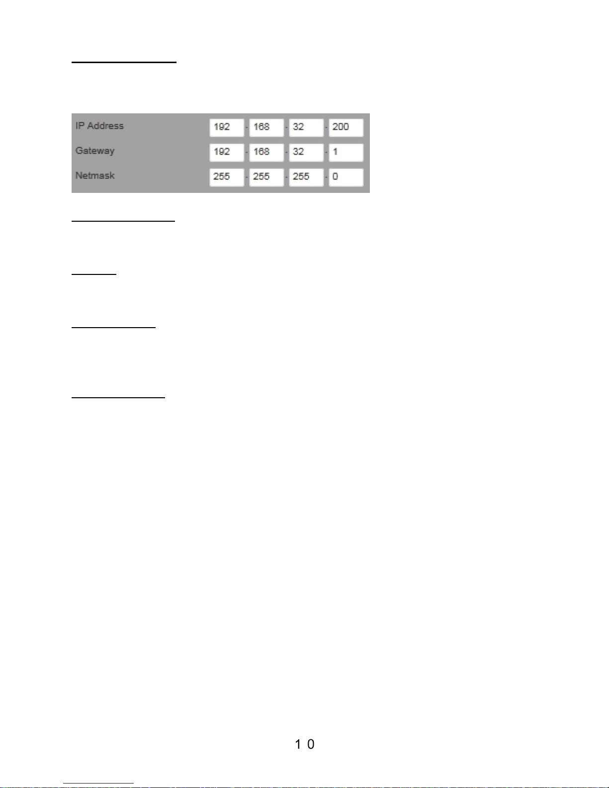
Network Page
Camera network settings (please refer to page 5 & 6 on how to change)
Camera Name
Allows you to change the name of the camera (upto 60 characters)
DHCP
Tick to enable if your network supports DHCP
Default Port
Change the port to suit your network
Defaulted to: TCP / IP = 80 / HTTPS = 443
RTSP Server
Change the port to suit your network
Defaulted to: 8554
NOTE: to ensure any changes to the network page are retained,
please refer to page 5 of this manual for the correct procedure.
Page 18
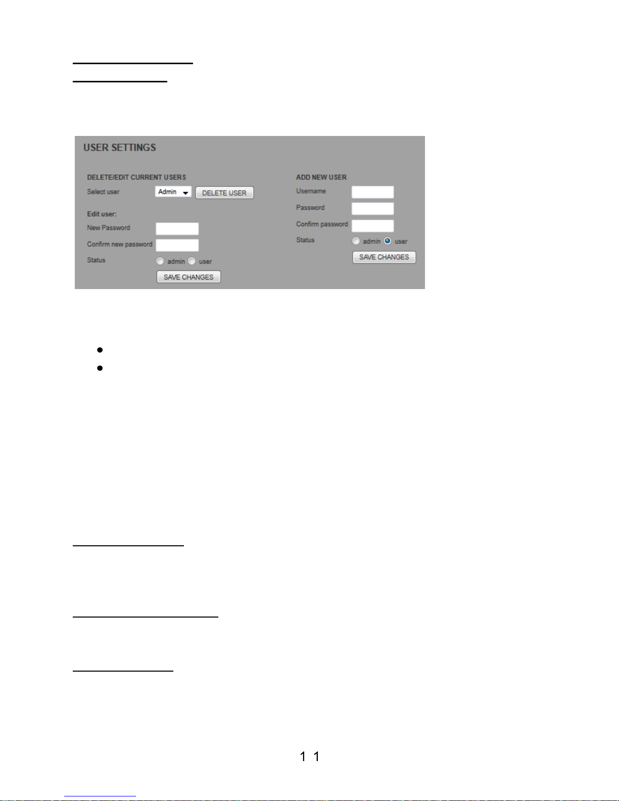
Advanced Page
User settings
Different levels of access to the camera and its features are available.
Two levels of user access are available:
Administrator – all camera functions are available
User – only camera viewing and PTZ operations are permitted
The default administrator is called ‘Admin’ and cannot be removed. The
default password for this user is also ‘Admin’ and this password may be
changed. If this password is changed, it can only be restored by
restoring factory defaults via the reset button on the back of the camera
(see page 18).
20 further additional users can be added if required.
Camera Details
This will list the following information:
Software version / OS Version / Hardware / Firmware / Website (Pages)
Camera Date / Time
Set current date and time via the drop down boxes
Set Language
Select one of the following from the drop down:
English / Russian / German / French / Spanish / Italian / Dutch /
Portuguese
Page 19
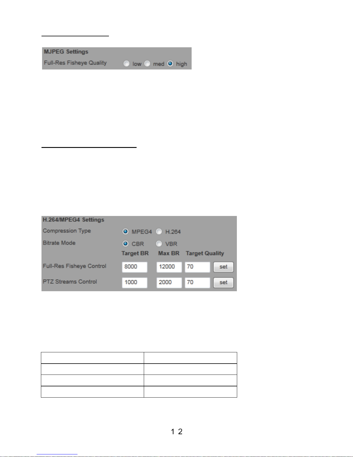
MJPEG Settings
Select the Full fish eye quality:
Low (50%): 250KB/frame
Medium (70%): 350KB/frame
High (80%): 400KB/frame
Max bandwidth at full frame rate: 12fps @ 400KB = 4.8Mbit/s
H.264/MPEG4 Settings
Compression Type:
Select between either MPEG-4 or H.264 (you will be asked to save
settings and restart camera to accept this change)
Bitrate Mode:
Select between CBR (Constant Bitrate) or VBR (Variable Bitrate) modes
CBR (Constant Bitrate):
In CBR mode only the Target BR column applies, so select the Target
BR value you want for Fisheye and PTZ Streams, then click 'set' button
to the right to save this setting.
View
CBR Target BR
Full-Res Fisheye Control
3000kbit/s (default)
PTZ Streams Control
1000kbit/s (default)
Range selectable
50 - 5000kbit/s
Page 20

VBR (Variable Bitrate):
In VBR mode both Max BR and Target Quality applies, so select the
Max BR value and Target Quality value you want for both Fisheye and
PTZ Streams, then click 'set' button to the right to save this setting.
View
VBR Max BR
Target Quality
Full-Res Fisheye Control
10000kbit/s (default)
70 (default)
PTZ Streams Control
2000kbit/s (default)
70 (default)
Range selectable
50 - 12000kbit/s
50 - 90
In VBR the camera encodes at the Target Quality unless the size of the
encoded data is greater than the Max BR. It then temporarily reduces
the image quality to keep under the maximum bit rate. Once quality is
below a set level, the encoder drops frames to keep within the Max BR
figure.
Misc Settings
Flicker Frequency:
Off / 50Hz / 60Hz
Disable Status LED:
Tick box to disable the LED
Auto Lowlight:
Tick box to enable automatic colour/monochrome switching
Gamma:
Use the drop down box to select the level:
0.5 / 0.6 / 0.7 / 0.8 / 0.9 / 1
Page 21
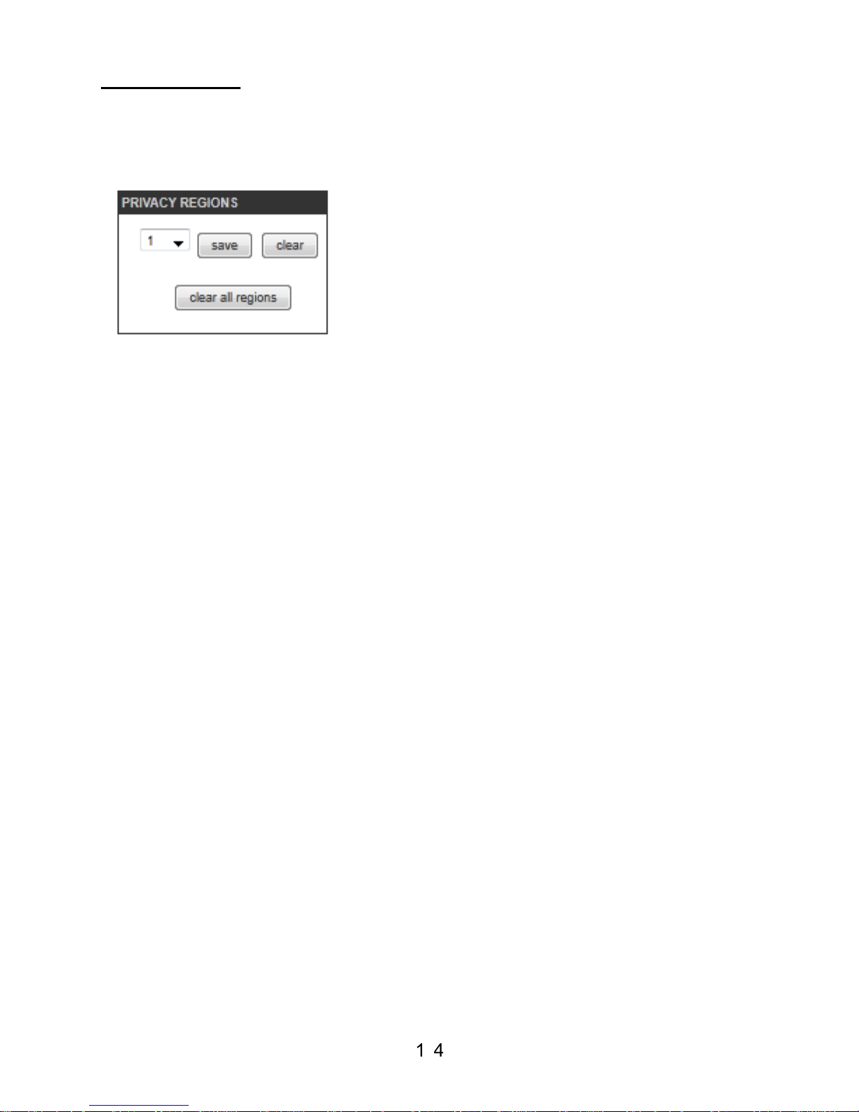
Privacy Page
This page allows the setting up of up to 10 dynamic privacy zones which
once saved are then applied to all camera IP streams:
To set a privacy zone
1. Select from the drop down box which zone you want to apply
2. Using the mouse, click 4 points on the image that you want to
obscure (lines are automatically joined up)
3. Click save if you wish to accept / click clear if you want to amend
If you wish to delete a previously applied privacy zone, select via the
drop down box and click the ‘clear’ button
The ‘clear all regions’ button deletes all previously stored privacy zones
Page 22
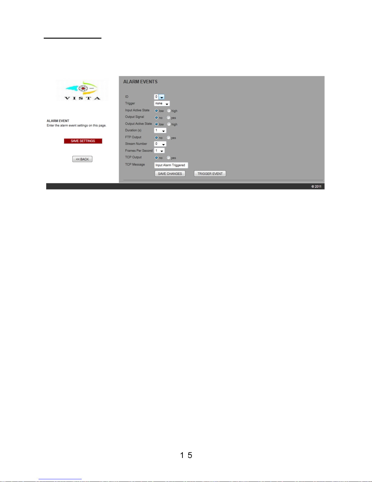
Events Page
The Alarm input and Alarm output can be configured from the Events
page, which is selected from the main page menu bar.
To setup alarms:-
1. Set the Trigger pull down to Input
2. Set the Input Active signal state to Low or High as required (Low
= NO going CLOSED on alarm, High = NC going OPEN on
alarm).
3. Set the Output Signal to yes, if required and set its Active state
to low or high (Low = NC going OPEN on alarm, High = NO
going CLOSED on alarm).
4. With this set, the alarm output signal will be switched when the
alarm is triggered.
5. Set the duration of the alarm
6. FTP - Set whether images are to be sent via FTP during the
alarm period. The FTP server details must be set up on the
Network page, to use this feature.
a. Set the View number to be sent via FTP (see Video
Streams in section 4 below)
b. Set the number of Frames per second to be set via FTP.
The duration times the frames per second will give the
total number of frames to be sent for each alarm trigger.
7. Click Save Changes to store the settings
The Trigger Event button can be used to manual trigger the alarm and
to test the setup.
Page 23

SPECIFICATION
Eclipse²
Camera
Image Sensor
1/2.5'' CMOS 5MP
Lens
F2.0 185⁰ Fisheye
Responsivity
0.5Lux @F2.0 (colour)
Max Resolution
2144 x 1944
Signal to Noise Ratio
38dB Max
Auto Exposure
Off / On
Flicker Frequency
Off / 50Hz / 60Hz
Auto Low Light
Off / On (colour / monochrome operation)
Low Light
Off / On (monochrome operation)
Gamma
0.5 / 0.6 / 0.7 / 0.8 / 0.9 / 1
Global Image Settings
Exposure / Saturation / Gain / Sharpness
(via individual slide bars)
Per-View (stream) Image
Settings
Brightness / Contrast / Quality
(via individual slide bars)
Languages
English / Russian / German / French / Spanish
Italian / Dutch / Portuguese
Status LED Operation
On / Off
Preset Positions
10 (de-warped streams 1-8 inclusive)
Privacy Zones
10 dynamic areas
Orientation
Ceiling / Wall / Table
Video
Compression
MJPEG & H.264 or MPEG-4
Frame-rate
12.5fps at Max Res
Streaming
Multiple simultaneous ePTZ and Panoramic
streams
Security
Password Protection, HTTPS encryption
Protocols
TCP/IP / DNS / DHCP / RTP / RTSP / RTCP /
IPv4 / HTTP / HTTPS / FTP
Users
Admin & User (max 20)
Simultaneous connections
14
Video Streams
Number
Description
0
2144x1944 (Fisheye)
1-4 (single streams)
640x480 (De-warped ePTZ)
5-8 (one quad stream)
320x240 (De-warped ePTZ)
9
640x480 (Fisheye)
10-11
640x240 180⁰ (Panoramic ePTZ)
Page 24

12
1280x720 HD 360⁰ (De-Warped Panoramic
ePTZ)
13
1280x240 HD 360⁰ (Panoramic ePTZ)
Type
HTTP / RTSP
Bit rate
MJPEG: 250KB/frame to 4.8Mbit/s
(CBR) H.264 or MPEG-4: 50 to 5000kbit/s
(VBR) H.264 or MPEG-4: 50 to 12000kbit/s
(Target Quality: 50 to 90)
System Integration
Application Programming
Interface
Open API for integration with NVR and VMS
systems
Playback Software
Developers Kit
SDK for ePTZ and panoramic view creation in
NVR playback software
Alarms
1 x Alarm Input, 1 x Alarm Output
Alarm Triggers
External input
Alarm Events
File upload via FTP, external output activation
General
Power
PoE IEEE 802.3af. Class 2
12-24VDC Max 6W
Colour
RAL7035
Construction
Die-Cast Aluminium
Weight (net)
650g
Weight (gross)
900g
Dimensions (unit)
147.5mm Ø, 54mm height
Dimensions (boxed)
170 (W) x 170 (H) x 170 (D)
Operating Temperature
0 - 50⁰ C
Storage Temperature
-10 to 60⁰ C
Operating Humidity
60% humidity, non-condensing
Approvals
CE: EN55022:2010 (Class B) , EN50130-
4:1995, +A1: 2001, +A2:2003 (Class A)
Page 25
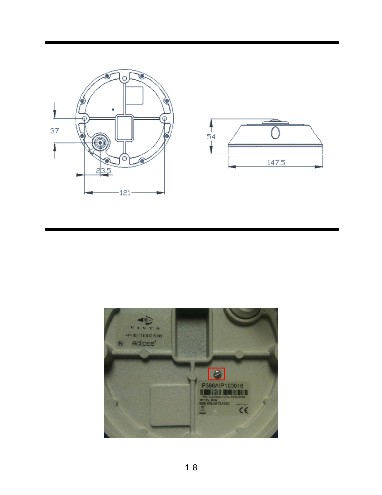
LINE DRAWING
FACTORY DEFAULT
1. Remove camera from installed location (leave powered up)
2. Remove screw entirely (highlighted below)
3. Insert pin/paperclip and hold until the LED cycles from red to amber
to green (approx 10 secs)
4. Camera will then reboot (this can take up to 2mins)
5. Reconnect to the camera (refer to page 4 of this manual if unsure)
Page 26

CAMERA STREAMS
To individually select a stream from a camera for a specific view only (note
that this is the stream only and there is no ePTZ), then the following
commands can be entered into your web browser address bar.
HTTP Stream (MJPEG)
http://ipaddress/mjpg/video.cgi?view=0&maxfps=4
‘view=’ can be set from 0 to 13:
0 = Full Fisheye 2144x1944
1-4 = 640x480 de-warped ePTZ
5-8 = 320x240 de-warped ePTZ
9 = 640x480 Fisheye
10-11 = 640x240 180 Panorama
12 = 1280x720 HD de-warped ePTZ
13 = 1280x240 HD 360 Panorama
‘maxfps=’ can be set at:1,2,4,6,12
RTSP (MPEG4 or H.264)
rtsp://ipaddress:8554/stream0
Stream number can be set from 0 to 13
0 = Full Fisheye 2144x1944
1-4 = 640x480 de-warped ePTZ
5-8 = 320x240 de-warped ePTZ
9 = 640x480 Fisheye
10-11 = 640x240 1800 Panorama
12 = 1280x720 HD de-warped ePTZ
13 = 1280x240 HD 3600 Panorama
Page 27

Eclipse
2
Manual / V1.0 / April 2012
(subject to change without notice)
 Loading...