

Vista Columbus Triplex User Manual
B
A
F M
192103114125136147158
n
R
16
E
N
T
E
R
VC16Te
VViissttaa C
Coolluu
mbbuuss TTrriipplleexx©
m
Digital Video Multiplexer/Recorder
User Manual
WARNING!
To prevent fire and electric shock, do not expose this product to rain or moisture.
The lightning flash with the arrowhead symbol,
within an equilateral triangle, is intended to alert
the user to the presence of uninsulated
"dangerous voltage" within the products enclosure
that maybe of sufficient magnitude to constitute a
risk of electric shock to persons.
CAUTION!
To prevent electric shock, do not remove cover.
No user serviceable components inside. Refer
servicing to qualified service personnel.
!
The exclamation point, within an equilateral
triangle, is intended to alert the user to the
presence of important operating and maintenance
(servicing) instructions in the literature
accompanying the product.
!
CAUTION! Lithium Battery
Danger of explosion if battery is
incorrectly replaced. Replace only
with the same or equivalent type
This equipment generates, uses and can radiate radio frequency energy, and if not installed and used
in accordance with the instructions in this manual, may cause interference to radio communications. It
has been tested and found to comply with the limits for a Class A computing device pursuant to subpart
J of part 15 of FCC rules which are designed to provide reasonable protection against such
interference when operated in a commercial environment. This equipment has also been tested and
found to comply with the requirements for a CE Class A device and TUV safety standards.
recommended by the
manufacturer.
Electrostatic-Sensitive Device!
Use proper CMOS and MOSFET handing precautions, including approved
grounded wrists straps, etc., to avoid damage to this unit or its internal
components, from electric discharge.
WARNING!
This product contains a recyclable lithium battery.
It may be illegal to dispose of this battery
improperly under local, state, or federal laws.
Check with your local waste management officials
for disposal and recycling options.
CAUTION!
ATTENTION
Operation of this equipment in a residential area may cause interference, in which case the user is
required to take all measures that are necessary, at the user's expense, to correct the interference.
0150-0202G 2 Vista Columbus Triplex

Contents
1 Vista Columbus Triplex Overview........................................................................ 5
1.1 Products Featured In This Manual...................................................................................5
1.2 Product Description.......................................................................................................... 5
1.3 Passwords.........................................................................................................................6
1.4 Unpacking ......................................................................................................................... 7
1.5 Installation Environment ..................................................................................................7
1.6 Associated Equipment .....................................................................................................8
1.7 The Back Panel ................................................................................................................. 8
1.8 Power-Up......................................................................................................................... 13
2 Columbus Triplex Basic Operations .................................................................. 15
2.1 Principal Operating Modes............................................................................................. 15
2.2 The Front Panel...............................................................................................................15
2.3 Live Viewing....................................................................................................................16
2.4 Playback.......................................................................................................................... 17
2.5 Recording........................................................................................................................19
2.6 Display Options ..............................................................................................................20
2.7 Active Cameos ................................................................................................................ 20
2.8 Sequencing ..................................................................................................................... 21
2.9 On-screen Indicators ......................................................................................................22
2.10 Triplex Mode ................................................................................................................... 23
3 Menu System Overview....................................................................................... 26
3.1 Menu Notation In This Manual........................................................................................26
3.2 Accessing The Menu System ......................................................................................... 26
3.3 Available Menus..............................................................................................................26
3.4 Menus In This Manual.....................................................................................................27
3.5 Navigating The Menu System......................................................................................... 27
3.6 Menu Shortcuts............................................................................................................... 27
3.7 The Main Menu................................................................................................................28
3.8 Time/Date ........................................................................................................................ 28
3.9 Record............................................................................................................................. 30
3.10 Alarms ............................................................................................................................. 38
3.11 Macro...............................................................................................................................41
3.12 Motion Detection.............................................................................................................43
3.13 Camera Titles .................................................................................................................. 46
3.14 Camera Setup..................................................................................................................47
3.15 Archive Setup..................................................................................................................48
3.16 Audio Setup ....................................................................................................................49
3.17 Telemetry.........................................................................................................................50
3.18 Communications.............................................................................................................52
0150-0202G 3 Vista Columbus Triplex

3.19 Front Panel Lock.............................................................................................................55
3.20 Factory Settings..............................................................................................................55
3.21 Passwords.......................................................................................................................55
3.22 The Operator Menu.........................................................................................................56
4 Alarms .................................................................................................................. 58
4.1 Alarm Input......................................................................................................................58
4.2 Alarm Output...................................................................................................................58
4.3 Alarm Acknowledge........................................................................................................58
4.4 On-screen Displays During Alarms................................................................................58
4.5 Alarm Operations During Playback................................................................................58
4.6 Alarm History Box...........................................................................................................59
4.7 Searching For Recorded Alarms....................................................................................59
5 Searching ............................................................................................................. 60
5.1 Disk Analysis Screen......................................................................................................61
5.2 Quick Archive to CD .......................................................................................................61
5.3 Search Filters..................................................................................................................62
5.4 Retail Search................................................................................................................... 63
5.5 Search Results................................................................................................................ 65
6 Web Interface ....................................................................................................... 67
6.1 WaveBrowser Overview and Controls ...........................................................................68
6.2 Vista Columbus Triplex WaveLink ................................................................................. 70
7 Technical Specifications..................................................................................... 72
8 RS232 Event Generation/Text Insertion Protocol ............................................. 74
8.1 Message Structure..........................................................................................................74
8.2 Message Type .................................................................................................................74
8.3 Alarm/Event Field............................................................................................................ 74
9 RS232 Remote Control Protocol ........................................................................76
9.1 Front Panel Button Emulation........................................................................................76
9.2 Configuration and Status ...............................................................................................77
10Macro Tables........................................................................................................ 78
10.1 Macro Functions Table................................................................................................... 78
11Warranty and Service.......................................................................................... 79
11.1 Factory Service............................................................................................................... 79
0150-0202G 4 Vista Columbus Triplex
1 Vista Columbus Triplex Overview
1.1 Products Featured In This Manual
VC04Te: Digital Video Multiplexer/Recorder (DVR), Four-Channel, Colour, Triplex.
VC10Te: Digital Video Multiplexer/Recorder (DVR), Ten-Channel, Colour, Triplex.
VC16Te: Digital Video Multiplexer/Recorder (DVR), Sixteen-Channel, Colour, Triplex.
1.2 Product Description
The Columbus Triplex is a video multiplexer capable of recording from multiple cameras to an internal
hard drive while simultaneously providing playback. Unlike outdated time-lapse VCRs, the Columbus
Triplex records high-resolution pictures. Digital recording improves playback quality over VCRs, and
eliminates the hassle of cleaning heads, changing tapes or servicing motors. The unit can also be
programmed to record continuously by overwriting the oldest recorded data. Depending on the setup,
the Columbus Triplex can store from a few hours to more than 3 years of colour images.
Programmable search features eliminate time consuming Fast Forwarding or Rewinding of tapes,
searching for critical data. Search for recorded images or events by alarm, time, date, motion, video
loss, camera number and ASCII cash register or ATM text.
Caution! This products primary purpose is to furnish video multiplexing and recording.
Although the unit has alarm handling and motion detection functions, they are considered
secondary features. This unit should not be the only alarm device on site.
Features
• Multiplexer functionality with built-in digital recording.
• Triplex simultaneous recording, playback, and live multiscreen viewing.
• Remote programming and control through the RS232, RS485 and Ethernet ports.
• View live or recorded images remotely using WaveReader software.
• Video motion detection (intrusion and activity).
• Preview search results with thumbnail images.
• Displays include full screen, sequenced, picture-in-picture, and multiscreens.
• Alarm Handling with History Log. Pre- and post alarm recording.
• Archive onto Vista VAIDe Disk Array, or RAID, or CD-R’s.
• IEEE 1394 Firewire interface for Vista VAIDe Disk Array or Firewire Disk Drives.
• Continuous Recording with simultaneous Archiving.
• PTZ control via ethernet or POTS, or via RS485 with the NPX/RKB remote keyboard.
• Covert camera recording (recording without display).
• Auto-Daylight savings time change function.
• Integrated WaveBrowser Software.
• Alarm Notification via email.
• Dynamic IP addressing (DHCP).
• Clock synchronization with Network Server.
• Support for Dynamic Domain Name Server (DDNS).
• Retail Text Search.
• Playback and live audio via WaveReader on audio supported models.
• Support for over a dozen languages.
• Hard Disk monitoring and testing features.
0150-0202G 5 Vista Columbus Triplex

1.3 Passwords
Passwords are provided to limit access to menus and certain functions. Two levels of password
security are provided:
• Operator: Limited menu access, only Operator and System View menus are available.
• Installer: Complete menu access.
As a security measure, it is recommended that the Operator and Installer passwords be changed after
installation is complete (see section 3.21). Store the passwords in the administrator’s secure files.
Default Passwords
Four-Channel Units
Password
Type
Operator Operator
Installer Installer
Factory
Defaults
Language Installer
Ethernet
Access
Reset
Access
Level Function
Installer
Installer
Provides access to the Operator
menu.
Provides access to all on-screen
menus.
Resets the multiplexer to the
factory defaults (except the time,
date, email addresses, and email
IP address).
Provides access to the On-screen
Language menu.
Deactivates the ethernet
password, so that any PC
equipped with WaveReader may
access the unit.
Changeable
by user?
Yes
Yes 3 4 4
No 4 1 1
No 1 2 3
No 1 1 1
Press ‘ENTER’
Default
Password
3 Times
0150-0202G 6 Vista Columbus Triplex

Ten and Sixteen-Channel Units
Password
Type
Operator Operator
Installer Installer
Factory
Defaults
Language Installer
Ethernet
Access
Reset
Access
Level Function
Provides access to the Operator
and SystemView menus.
Provides access to all on-screen
menus.
Resets the multiplexer to the
Installer
Installer
factory defaults (except the time,
date, email addresses, and email
IP address).
Provides access to the On-screen
Language menu.
Deactivates the ethernet
password, so that the unit may be
accessed by any PC equipped with
WaveReader.
Changeable
by user?
Yes
Yes 3 4 7
No 4 1 1
No 1 2 3
No 1 1 1
Press ‘ENTER’
Default
Password
3 Times
1.4 Unpacking
Check the package and contents for visible damage. If any components are damaged or missing, do
not attempt to use the unit, contact the supplier immediately. If the unit must be returned, it must be
shipped in the original packing box.
Package Contents
• The Columbus Triplex unit.
• The Alarm Interface Circuit Board.
• Accessory PCB. Audio equipped models only.
• The User Manual.
• A WaveReader Software CD.
• The WaveReader Software Manual.
• The Archiving Addendum.
• Rack Mount Adapters.
• Power Supply.
• Power Cord.
1.5 Installation Environment
Power: Ensure that the installation site’s AC power is stable and within the rated voltage of the 12
Volt DC power supply. If the site’s AC power is likely to have spikes or power dips, use power line
conditioning or an Uninterruptable Power Supply (UPS).
Ventilation: Ensure that the location planned for the installation of the unit is well ventilated. Take
note of the locations of the cooling vents in the unit’s enclosure, and ensure that they are not
obstructed.
Temperature: Consider the unit’s operating temperature (0 to 40 °C) and non-condensing humidity
specifications (10% to 80%) before choosing an installation location. Extremes of heat or cold beyond
the specified operating temperature limits may cause the unit to fail. Do not install the unit on top of
other hot equipment. Leave space between rack mounted units.
0150-0202G 7 Vista Columbus Triplex
Moisture: Do not expose the unit to rain or moisture. Moisture can damage the internal components.
B
B
RS-485/1
ETHERNET
RS-485/2
RS-232/2
2345678
9
131415
Do not install the unit near sources of water.
Chassis: Other equipment may be placed on top of the unit if it weighs less than 35 pounds (16
kilograms).
1.6 Associated Equipment
Associated equipment in a typical security system could contain the following items:
• Two monitors
• A Keyboard (NPX/RKB).
• Video cameras: Composite video, 1 volt peak-to-peak.
• Alarm input devices: Pressure sensors, motion detectors, etc.
• Alarm output devices: Buzzers, Sirens, Flashing Lights, etc.
• A PC connected via ethernet cable.
• An external archive device, such as a VAIDe, RAID, or CD-R.
For instructions regarding the connection of the associated security equipment in your system, please
consult the instruction manual of the associated equipment.
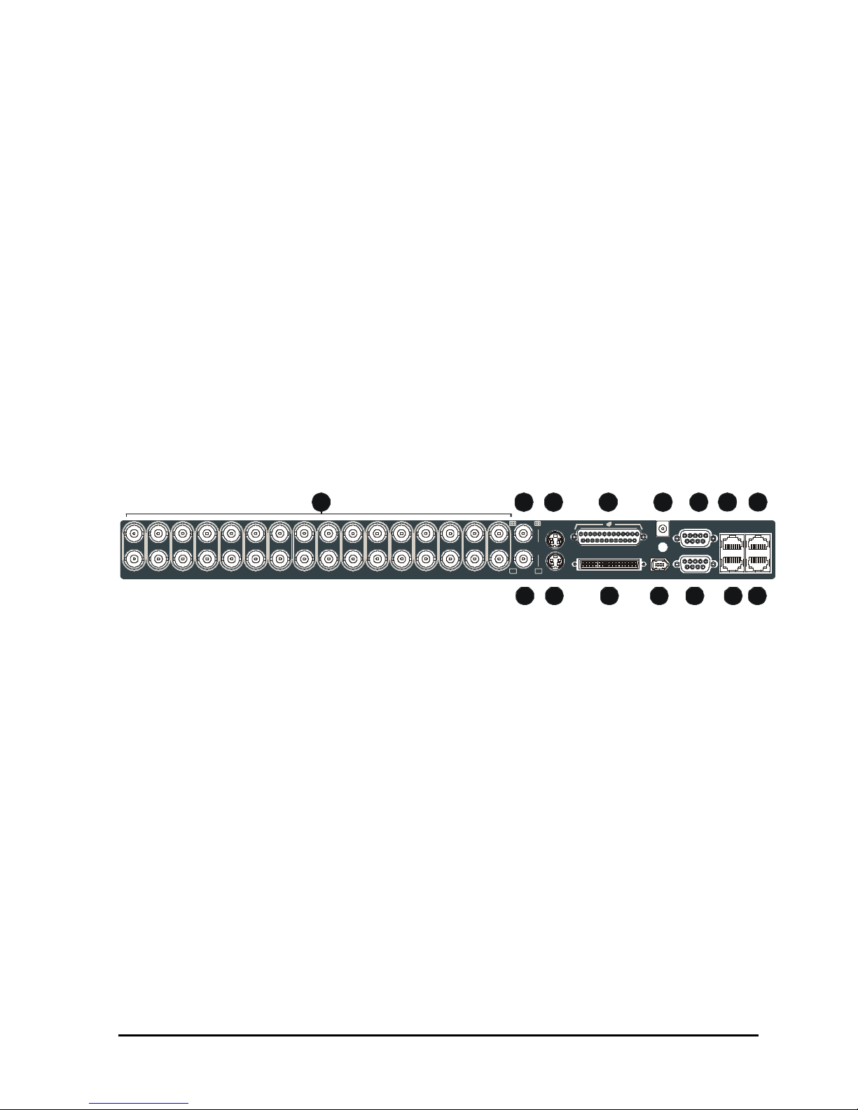
1.7 The Back Panel
1
AUX
1 2 3 4 5 6 7 8 9 10 11 12 13 14 15 16
SVHS
SCSI
12V DC
IEEE-1394
RS-232/1
10/100
10 11 12
1. Camera Inputs: BNC connector, looping. Auto Terminating.
2. Composite Monitor-A Output: Composite video output with BNC style connector.
3. Y/C Monitor-A Output: Y/C video output with 4-pin mini-DIN style connector.
4. Alarm I/O: For connecting alarm inputs, and alarm output relays.
5. Power Input: For connecting the power supply.
6. Aux Port: For connecting the Accessory PCB for Audio inputs and outputs.
7. RS485 Port 1 Connector: For connecting to keyboard and other RS485 devices.
8. 10/100 Ethernet Port: For connecting to remote PC via ethernet network.
9. Composite Monitor-B Output: Composite video output with BNC style connector.
10. Y/C Monitor-B Output: Not used.
11. SCSI Port: For connecting SCSI compatible archive devices.
12. IEEE 1394 Firewire Port: For connecting Firewire compatible archive devices.
13. RS232 Port 1: For modem connection and external control of the unit.
14. RS485 Port 2 Connector: For connecting to keyboard and other RS485 devices.
15. RS232 Port 2: For Event Generation and ASCII Text insertion.
0150-0202G 8 Vista Columbus Triplex
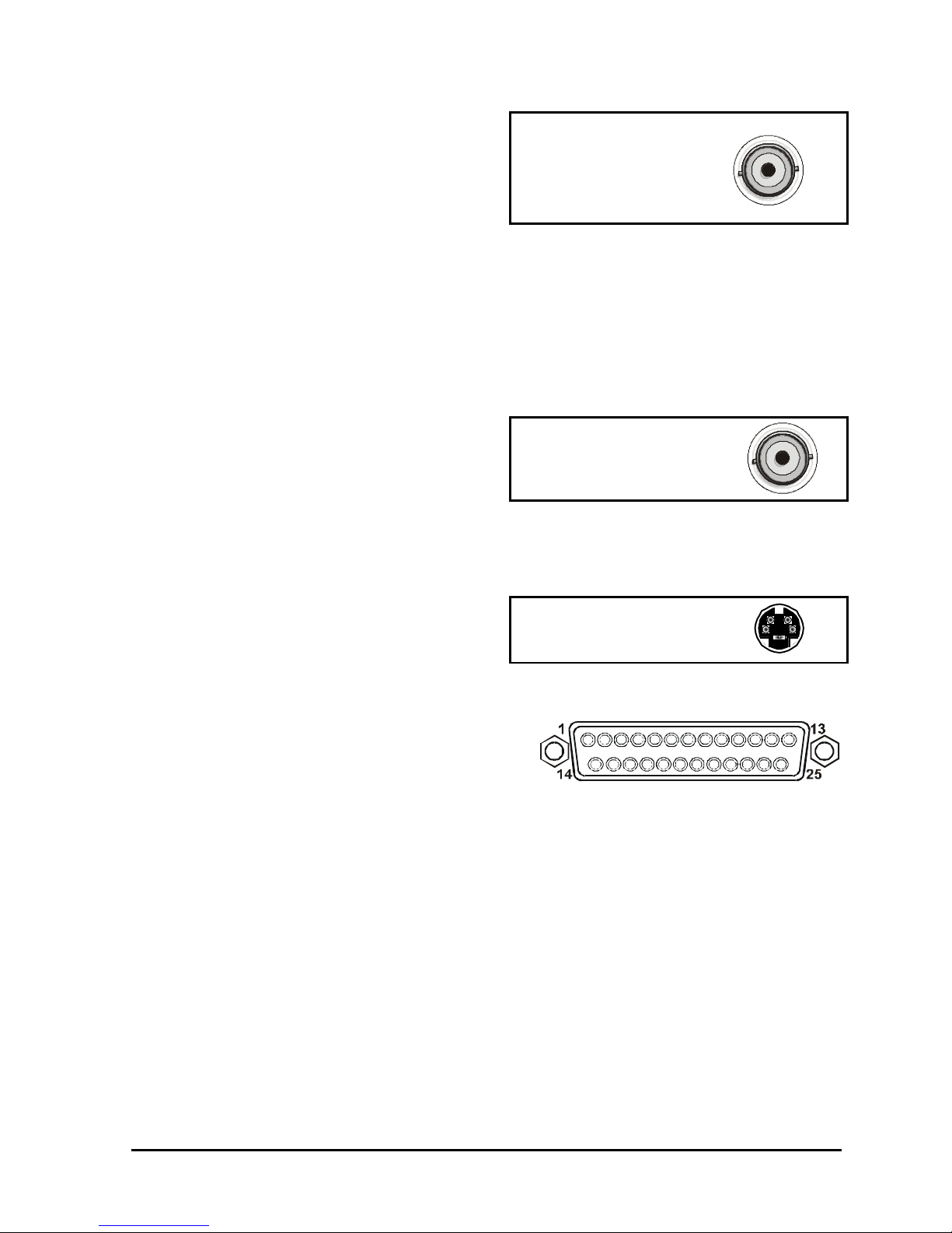
Camera Inputs
There are two BNC jacks for each camera. Either
jack can receive a camera signal. The signal is
looped (directly connected to the other jack), making
the camera signal available to other equipment.
The camera input connectors are Auto Terminating.
This means that the input signal will automatically be terminated with 75-Ohms unless a 2nd cable is
connected to the 2nd BNC connector of the same camera input. Make sure there is 75-Ohm
termination at the end of the video line if the signal is looped through the Columbus Triplex.
Time base correction is performed during digital capture. As a result, cameras do not require
synchronization.
See section 3.13 for information about disabling unused camera jacks in the menu system.
Cable: 75-Ohm Coaxial
Connectors: BNC
Auto Terminating: Yes
Passive Looping: Yes
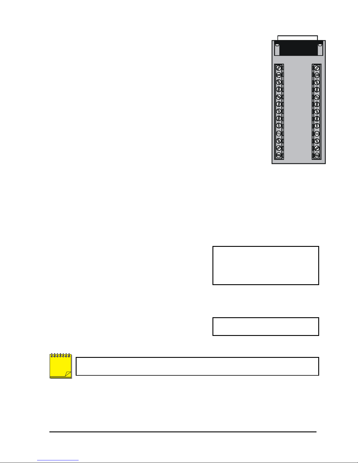
Composite Monitor Output (Monitor A Only)
When connecting directly from the Columbus Triplex
to the monitor, select the 75-Ohm impedance setting
on the monitor.
If an additional device is connected to the monitor’s looping output, set the termination of the additional
device as 75-Ohm, and set the termination of the monitor as Hi-Z (High Impedance).
Cable: 75-Ohm Coaxial
Connectors: BNC
Y/C Monitor Output
Y/C video output has a 4-pin mini-DIN style
connector. This style of connection is also referred to
as SVHS and S-Video.
Cable: 75-Ohm Coaxial
Connectors: BNC
Alarm I/O Port
The back panel of the unit is equipped with an Alarm
Port (DB-25 style connector).
Do not attempt to wire directly to the DB-25
connector on the back panel.
Connect the Alarm PCB (supplied with the unit) to the Alarm Port. Wire all alarm inputs to the Alarm
PCB per the pin out specifications shown below.
DB-25 Connector on Back Panel
0150-0202G 9 Vista Columbus Triplex
Pin 1: Alarm Input 1.
A
7
G
N
D
Pin 13: Alarm Input 13.
Pin 2: Alarm Input 2.
Pin 3: Alarm Input 3.
Pin 4: Alarm Input 4.
Pin 5: Alarm Input 5.
Pin 6: Alarm Input 6.
Pin 7: Alarm Input 7.
Pin 8: Alarm Input 8.
Pin 9: Alarm Input 9.
Pin 10: Alarm Input 10.
Pin 11: Alarm Input 11.
Pin 12: Alarm Input 12.
Pin 14: Alarm Input 14.
Pin 15: Alarm Input 15.
Pin 16: Alarm Input 16.
Pin 17: Alarm Output Relay #1.
Pin 18: Ground.
Pin 19: Ground.
Pin 20: Ground.
Pin 21: Alarm Output Relay #1 Common.
Pin 22: Alarm Output Relay #2.
Pin 23: External Alarm Silence and Acknowledge Input.
Pin 25: Alarm Output Relay #2 Common.
Signal
PIN
NO1A1 A2A14 A15 A1 6A3 A4 A5 GND
171 214 1 5 163 4 5 1 8 7196
GNDA6
Alarm PCB
Active alarm inputs vary by DVR model. 4 channel units (VC04Te) have 4 active alarm inputs. 10
channel units (VC10Te) have 10 active alarm inputs.
Alarm Input
An alarm condition can be activated by devices such as pressure pads, passive infrared detectors,
door switches, or other similar devices.
Signal
PIN
NO2 COM1
22 2 1 208910 202311241213 25
A8A9A10 GNDACKA11VextA12A13 CO M2
Alarm Relay Output
The alarm relay output is activated when an alarm condition
exists. The alarm output is only active for the duration of the
alarm.
Alarm relays can be programmed in the menu system to
respond to macros, and video loss. See section 3.10 for
information about configuring the alarms in the menu system.
External Alarm Acknowledge Input
Connect a switch or similar device to ground this pin in order
to acknowledge an alarm condition, and silence associated
buzzers and relays. Connect from pin 23 to either pin 18, 19,
or 20 (ground pins).
NOTE
All specifications subject to change without notice. Norbain believes all specifications to be
correct at time of printing, but no liability is assumed for omissions or errors.
Output: Normally Open Zero
potential relay contacts,.
Voltage: 30V (Max)
Current: 500mA (Max)
External Device: Normally Open
Zero potential relay contact.
0150-0202G 10 Vista Columbus Triplex
AUX Port
1
5
6
9
123456789
GND
#24 AWG, twisted pair with shield
The back panel of the unit is equipped with an Aux Port
(DB-9 style connector).
Do not attempt to wire directly to the DB-9
connector on the back panel.
Connect the Accessory PCB (supplied with the unit) to the AUX port to access the Audio features.
Wire the audio input and output to the Accessory PCB per the pin out specifications shown below.
Pin 1: Not Used.
Pin 2: Audio Out.
Pin 3: Ground.
Pin 4: Audio In.
Pin 5: Ground.
Pin 6: Not Used.
Pin 7: Ground.
Pin 8: Not Used.
Pin 9: Ground.
GND: Ground.
Accessory PCB
DB-9 Connector on Back Panel
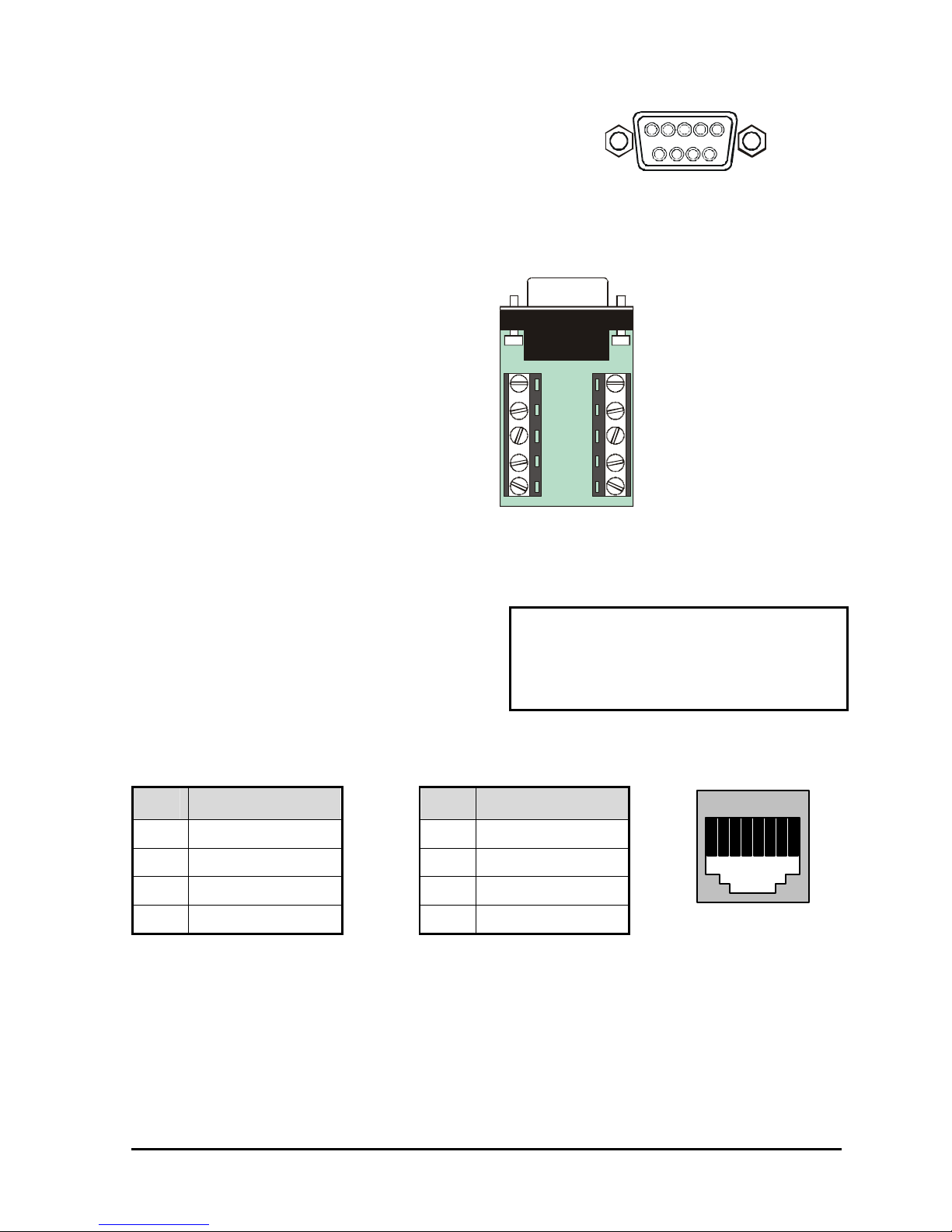
RS485 Connector
Shields are grounded at one end, preferably at the
Columbus Triplex.
See section 3.18 for information about configuring
the RS485 network address settings in the menu
system.
Wire Type:
Connector Type: RJ-45
Max. Cable Length: 3200 feet / 1000 meters
RJ-45 Pin Configuration For RS485 Port
Pin Use
1 Ground (Shield) 5 Not Connected
2 +12V DC (200mA) 6 Network -VE
3 Network +VE 7 Ground (Shield)
4 Not Connected 8 +12V DC (200mA)
Pin Use
(2-wire)
82 3 4 5 6 71
RJ-45 Socket on
Back Panel
0150-0202G 11 Vista Columbus Triplex
Ethernet Port
The cable connection configuration depends on your
network configuration:
• For a Columbus Triplex that connects directly to
a Hub or Switch, use a straight through
connection.
Wire Type: Cat 5
Connector Type: RJ-45
Max. Cable Length: 100 meters / 328 ft.
Min. Cable Length: 6 feet / 1.8 meters
• For a Columbus Triplex that connects directly to
a PC, use a cross over connection.
Consult with your MIS personnel for the specific type
of configuration. See section 3.18 for information
about configuring the ethernet settings in the menu
system.
Hub Wiring Configuration: Straight Through
PC Wiring Configuration: Cross Over
RJ-45 Pin Configuration For Ethernet Port
Pin Use
1 TX+ 5 Not Connected
2 TX- 6 RX-
3 RX+ 7 Not Connected
4 Not Connected 8 Not Connected
Pin Use
SCSI Port
The unit is equipped with a SCSI port for
connecting external archive devices. The unit only
supports a single SCSI device. The SCSI ID of the
archive device must be set to 0.
The SCSI bus must be terminated, otherwise the
system will not operate properly.
Additional menu setup may be necessary to
configure archive device. See section 3.15.
Connector: 50 Pin, High Density SCSI-2.
Gender (on unit) : Female
Compatible devices : VAIDe, RAID, CD-R,
CD-RW
SCSI ID : 0
RJ-45 Socket on
Back Panel
82 3 4 5 6 71
SCSI and IEEE 1394 archiving devices should not be connected to the Vista Columbus
NOTE
Triplex simultaneously. Archiving support is only available for one or the other type of
interface at a time.
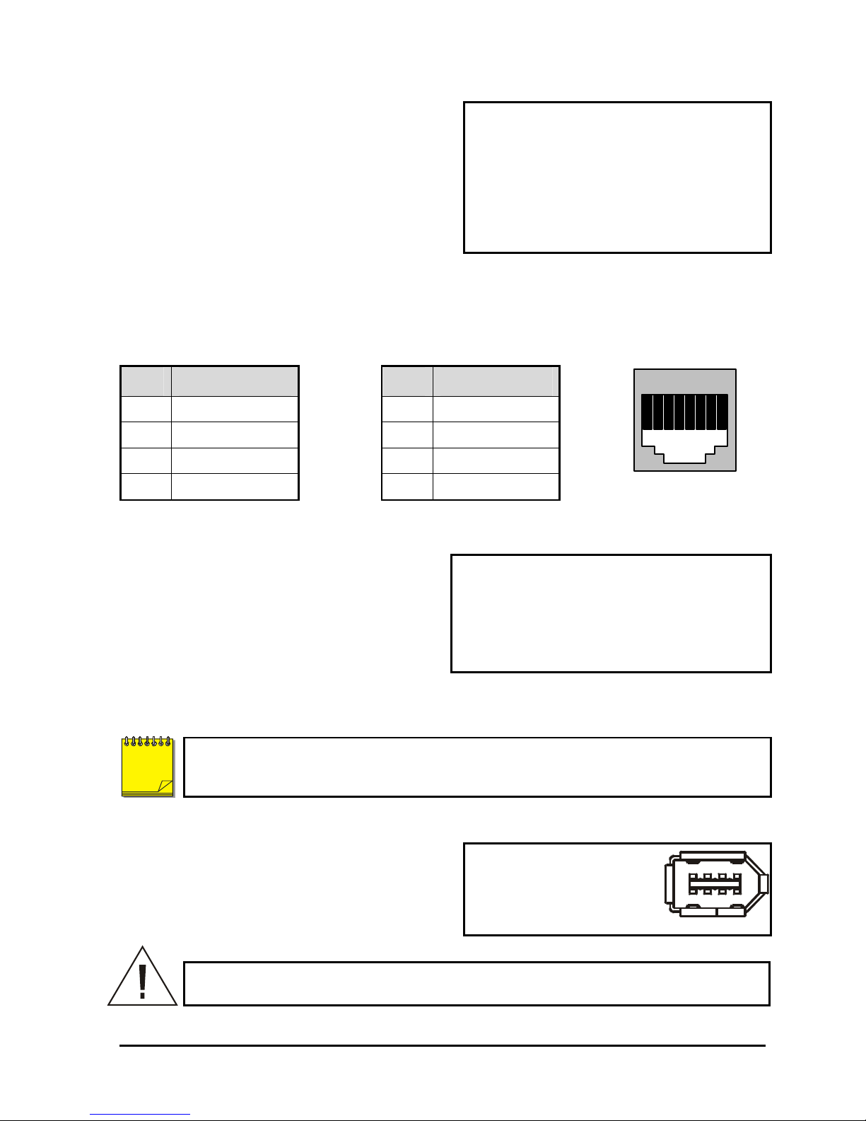
IEEE 1394 Firewire Port
The unit is equipped with an IEEE 1394 Firewire port
for connecting Firewire compatible external archive
devices. For information on the approved devices,
please refer to the Archiving Addendum manual that
is supplied with this unit.
Caution! Ensure the power to Vista Columbus Triplex is OFF BEFORE connecting any
SCSI or 1394 devices. Do not attempt to use the SCSI and 1394 ports simultaneously.
0150-0202G 12 Vista Columbus Triplex
Cable: 6 position Firewire
Connectors: 6 position DIP
1
5
6
9
Slide approximately 6 inches of the power cord through the pre-installed
Loop the power cord end around and insert into the power receptacle on
RS232 Port 1
For a Modem connection or remote control of unit. See section 3.18 for information about configuring
the modem settings in the menu system. See section 9 for RS232 Remote Control Protocols.
DB-9 Pin Configuration For Port 1
Pin Use
Pin Use
Pin Use
1 DCD 4 DTR 7 RTS
2 RX 5 Ground 8 CTS
3 TX 6 Not Connected 9 Not Connected
RS232 Port 2
For Event Generation, ASCII Text Insertion, and proprietary dome control.
RJ-45 Pin Configuration For RS232 Port 2
Pin Use
1 Ground 5 TXD
2 Reserved 6 Not Connected
3 Not Connected 7 Ground
4 RXD 8 Reserved
Pin Use
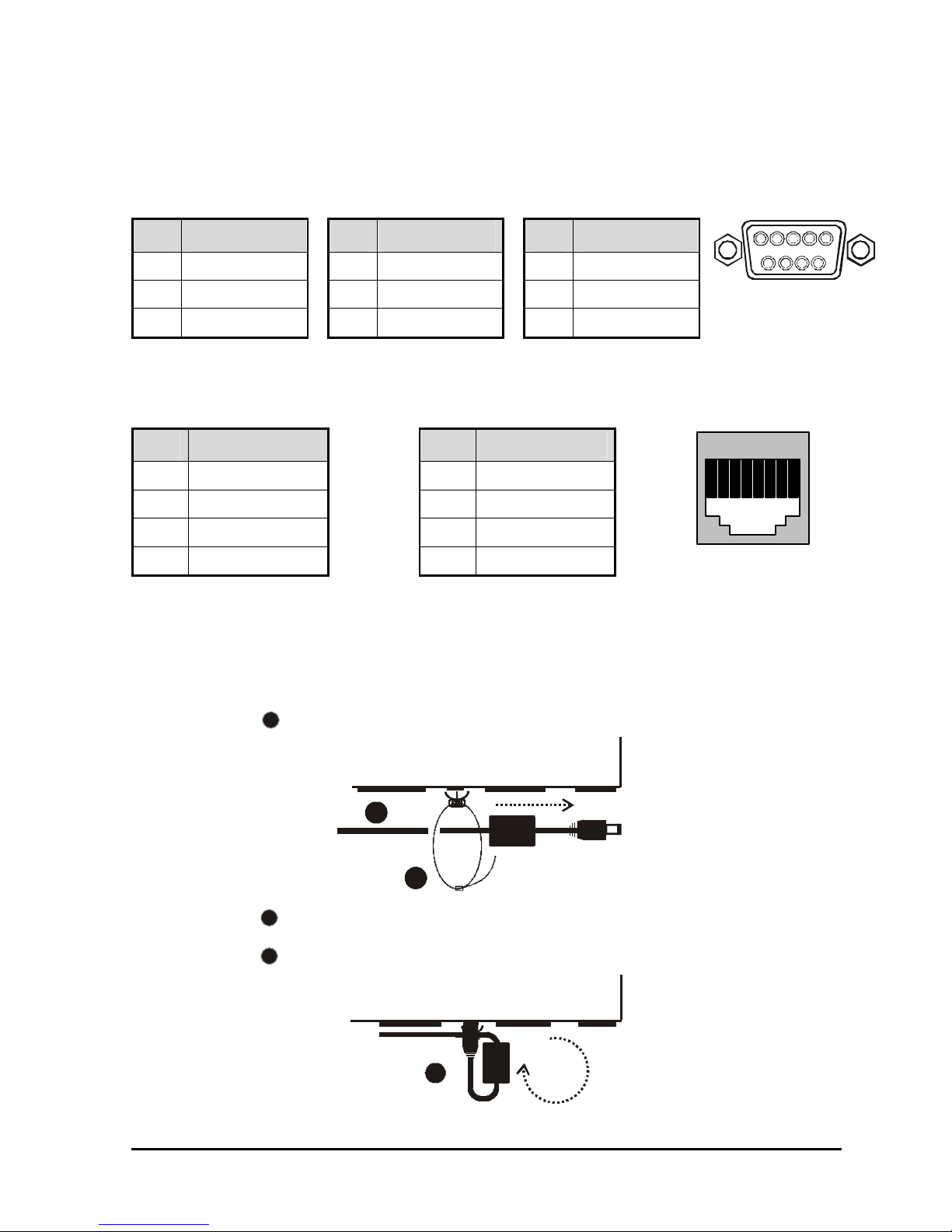
1.8 Power-Up
Use the diagram below to secure the power cord to the back panel.
1
cable tie (approximately 1 inch after the ferrite core).
DB-9 Connector on
Back Panel
82 3 4 5 6 71
RJ-45 socket on
Back Panel
1
2
Tighten the cable tie until the cord is secure. Do not over tighten.
2
3
the back panel.
0150-0202G 13 Vista Columbus Triplex
3

It is important that the power-up procedures be followed carefully. The unit uses its auto-detect
feature to detect camera signals during power-up, and configures itself automatically.
Power-up procedure
Once the system installation is complete, apply
power in the following order:
1. Energize the monitors and all of the cameras.
2. Energize the Columbus Triplex.
Once power is applied to the unit, it will begin its power-up procedure. The unit will begin by displaying
the software version on Monitor-A, then the unit will begin recording automatically.
Voltage: 12 Volt DC
Power: 60 Watt (5 Amp)
Connector: 2.1mm barrel, centre positive
Power Supply Input
Check Video Input Quality
Check the picture quality by selecting each camera for full screen display. If the picture quality is poor,
check the following items:
• The BNC connections.
• The loop-through terminations.
• The video levels of incoming signals.
• The possibility of ground loops.
• Consult the camera’s installation instructions for additional information about proper camera setup.
Check Record And Playback Quality
Record for at least three minutes at the default record rate. Then play back the recording, selecting
each camera for full screen display. Check the playback picture quality.
0150-0202G 14 Vista Columbus Triplex
2 Columbus Triplex Basic Operations
679
8
B
A
VC16Te
2.1 Principal Operating Modes
The Columbus Triplex has three principal modes of operation:
• Live Viewing.
• Playback.
• Recording.
All three of these modes can operate simultaneously. Each mode is discussed in detail later in this
section.
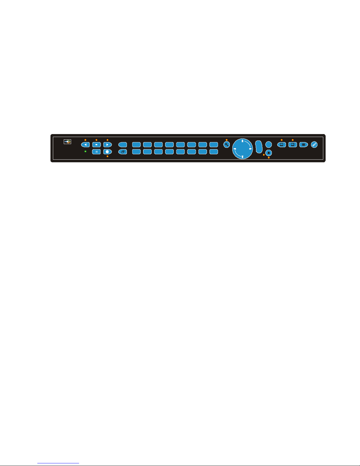
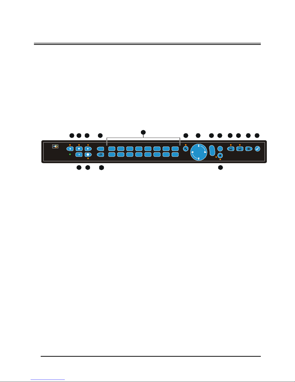
2.2 The Front Panel
1 2 3 4
5
10 12 13
11
192103114125136147158
F M
n
16R
16
E
N
T
E
R
171514
1. Reverse Play Button: Plays recorded video in reverse.
2. Live/Stop Button: Stops Playback and returns to Live mode.
3. Play Forward Button: Begins Playback.
4. Function Button: Used in conjunction with Camera Buttons to run macros. Also displays help
screens in certain modes.
5. Camera Selection Number Buttons: Camera numbers 1 through 16, 1 through 10, or 1 through 4.
6. Zoom Button: Provides a 2X digital zoom.
7. Arrow Buttons: Controls Playback speed and Menu selection.
8. Enter Button: Confirms selections in menus.
9. Menu Button: Provides access to on-screen menus.
10. Monitor A Select Button: Selects control on Monitor A.
11. Monitor B Select Button: Selects control on Monitor B.
12. Multiscreen Button: For selection of various multiscreen options.
13. Search Button: Provides access to stored video data.
14. Pause/Freeze Button: Freezes camera images on-screen in Live mode. Pauses Playback.
15. Record Button: Begins or Stops Recording.
16. Sequence Button: Sequences camera views.
17. Alarm Button: Allows user to acknowledge and silence alarms.
0150-0202G 15 Vista Columbus Triplex

2.3 Live Viewing
Multiscreen Display
In Live Multiscreen mode, press the Multiscreen button to activate the
multiscreen displays on Monitor-A or Monitor-B. Repeatedly pressing the
Multiscreen button advances the display to the next multiscreen. Live
Multiscreens are displayed with grey borders. For detailed information
about Multiscreen displays, see section 2.6.
Multiscreen Display With Sequencing
If a multiscreen display does not include all of the cameras, the remaining
cameras can be sequenced in the bottom right cameo. While in a multiscreen
display, press the Sequence button to begin sequencing. For detailed
information about sequencing, see section 2.8.
Full Screen Display
Select any camera for Full Screen display by pressing the Number button of
the desired camera. Pressing the Camera number button again displays the
Status Display Box. Pressing the same button a third time displays any
associated ATM or cash register ASCII text, see section 2.9.
Sequenced Full Screen Display
While in a Full Screen display, press the Sequence button to begin full
screen sequencing. The sequence list and dwell times are programmable.
For detailed information about programming the sequence list see section
2.8.
Multiscreen Button
Sequence Button
1
Number Button
Sequence Button
Zooming
To activate the 2x digital zoom, select the full screen display of the camera
you wish to zoom, then press the Zoom button. Zooming will be indicated by
the LED located directly above the Zoom button. Zooming is also indicated
as ZOOM on the primary monitor. Zooming works with frozen and non-frozen
images. Zoomed images can also be frozen.
While Zoomed, use the Arrow Buttons to Pan and Tilt across the image.
Please note, the camera does not move during digital Pan/Tilt.
Press the Zoom button again to cancel the Zoom operations.
If the Zoom button is pressed while in a multiscreen display, the camera from the last active
NOTE
cameo is selected for full screen display. Press the Zoom button again to activate the Zoom
operation.
Freezing
Pressing the Freeze button freezes all camera images on-screen. Full
Screen freezing is indicated as FRZ on-screen. Multiscreen freezing is
indicated as * (a flashing asterisk) in each frozen cameo.
Individual cameos can be frozen in Active Cameo mode (see section 2.7).
Press the Freeze button again or any camera button to cancel Freeze
operations.
Zoom Button
with LED
Freeze Button
0150-0202G 16 Vista Columbus Triplex
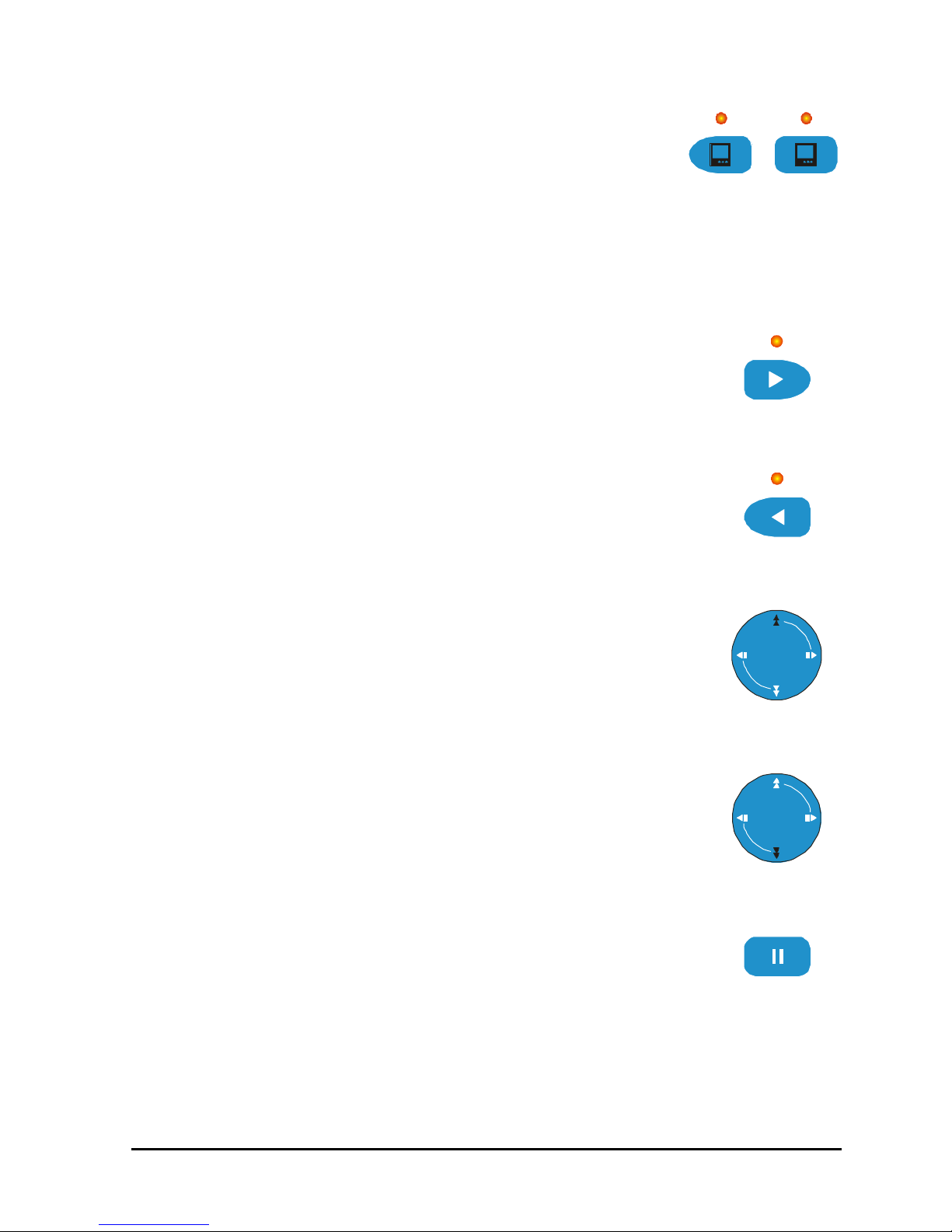
Selecting Monitor A or B
B
To select Monitor A or B, press the corresponding Monitor button. The LED
will light to indicate that the number keypad now controls the selected
monitor.
A
Monitor Buttons
2.4 Playback
Playback always displays on Monitor A. Playback multiscreen borders are black, as opposed to the
grey borders of the live multiscreens. Monitor B continues to display fullscreen live images in playback
mode. To begin playback, press the Play Forward or Reverse Play button.
Play Forward
When the Play Forward button is pressed, the unit will play forward at the rate
the data was recorded. While in Playback mode, the user may change the
playback direction, playback speed, etc. To return to Play Forward operations,
press the Play Forward button. The left and right arrows on the Arrow Button
will also change the playback direction when in play mode.
Reverse Play
To begin reverse playback, press the Reverse Play button.
Fast Forward
During playback, press the Up Arrow button. The unit will display images at a
higher than normal rate. There are 4 Fast Forward rates. Repeated pressing of
the Up Arrow button will increase the playback speed.
Play Forward
Button
Reverse Play
Button
Rewind
During playback, press the Down Arrow button. The unit will display images (in
reverse) at a higher than normal rate. There are 4 Rewind rates. Repeated
pressing of the Left Arrow button will increase the rewind speed.
Pause/Freeze
During playback, press the Freeze button. This feature pauses all full screen and
multiscreen images. Pause is indicated by FRZ on the playback monitor.
Up Arrow
Button
Down Arrow
Button
Freeze Button
0150-0202G 17 Vista Columbus Triplex

Single Frame Advance
While in Pause mode, press the Right Arrow button. The unit will advance a
single frame, then return to Pause mode.
Right Arrow
Button
Single Frame Rewind
While in Pause mode, press the Reverse Play button. The unit will rewind a
single frame, then return to Pause mode.
Left Arrow
Button
Stop Playback
To stop playback and return to Live Multiscreen mode on Monitor A, press the
Stop button.
Stop Button
Multiscreen Display
During Playback, press the Multiscreen button to activate a multiscreen
display. The 6-way and PIP multiscreen displays are not available in
Playback mode. For detailed information about Multiscreen displays, see
section 2.6.
Multiscreen Button
Multiscreen Display With Sequencing
If a multiscreen display does not include all of the cameras, the remaining
cameras can be sequenced in the bottom right cameo. While in a multiscreen
display, press the Sequence button to begin sequencing. For detailed
information about sequencing, see section 2.8.
Sequence Button
Full Screen Display
Select any camera for Full Screen display by pressing the Number button of
the desired camera. Pressing the Camera number button again displays the
Status Display Box. Pressing the same button a third time displays any
associated ATM or cash register ASCII text.
Number Button
1
Sequenced Full Screen Display
While in a Full Screen display, press the Sequence button to begin full
screen sequencing. The sequence list and dwell times are programmable.
For detailed information about programming the sequence list see section
2.8.
Sequence Button
Zooming
To activate the 2x digital zoom, select the full screen display of the camera you wish to zoom, then
press the Zoom button. Zooming will be indicated by the LED located directly above the Zoom button.
0150-0202G 18 Vista Columbus Triplex
Zooming is also indicated as ZOOM on the monitor. Zooming works with
Monitor A
Monitor B
Stop Mode
Playback Mode
frozen and non-frozen images. Zoomed images can also be frozen.
While Zoomed, use the Arrow Buttons to Pan and Tilt across the image.
Please note, the camera does not move during digital Pan/Tilt.
Press the Zoom button again, or another camera button to cancel the Zoom
operations.
NOTE
If the Zoom button is pressed while in a multiscreen display, the camera from the last active
cameo is selected for full screen display. Press the Zoom button again to activate the Zoom
operation.
Zoom Button
with LED
Searching Recorded Data
The Columbus Triplex has a powerful search interface feature that allows the user to search for data
on the internal hard disk or an external archive device. The user may search the data for previous
recording sessions, text insertion,or alarm conditions. Because the search interface is so dynamic, it
is covered in detail in a separate section of this manual. See section 5.
2.5 Recording
To begin recording, press the Record button. Recording will be indicated by the
LED located directly above the Record button. The unit always starts recording
at the end of previously recorded data.
The unit will continue recording until the record button is pressed again.
If Record Lock is active the Record button will not stop the unit from recording.
Record Button
R
Monitor Displays During Recording
Multiscreen Live and Playback display on Monitor A and Monitor B are not affected by recording
operations.
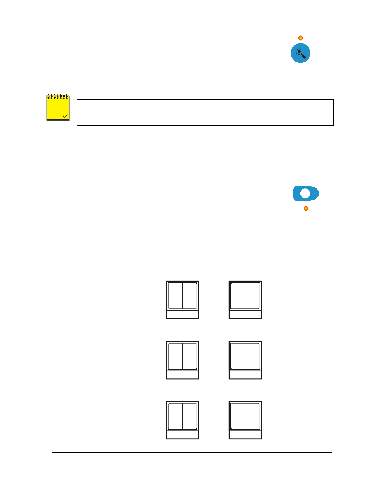
Triplex Mode
LIVE
PLAY
BACK
LIVE
PLAY
BACK
LIVE
LIVE
LIVE
0150-0202G 19 Vista Columbus Triplex
16-Way
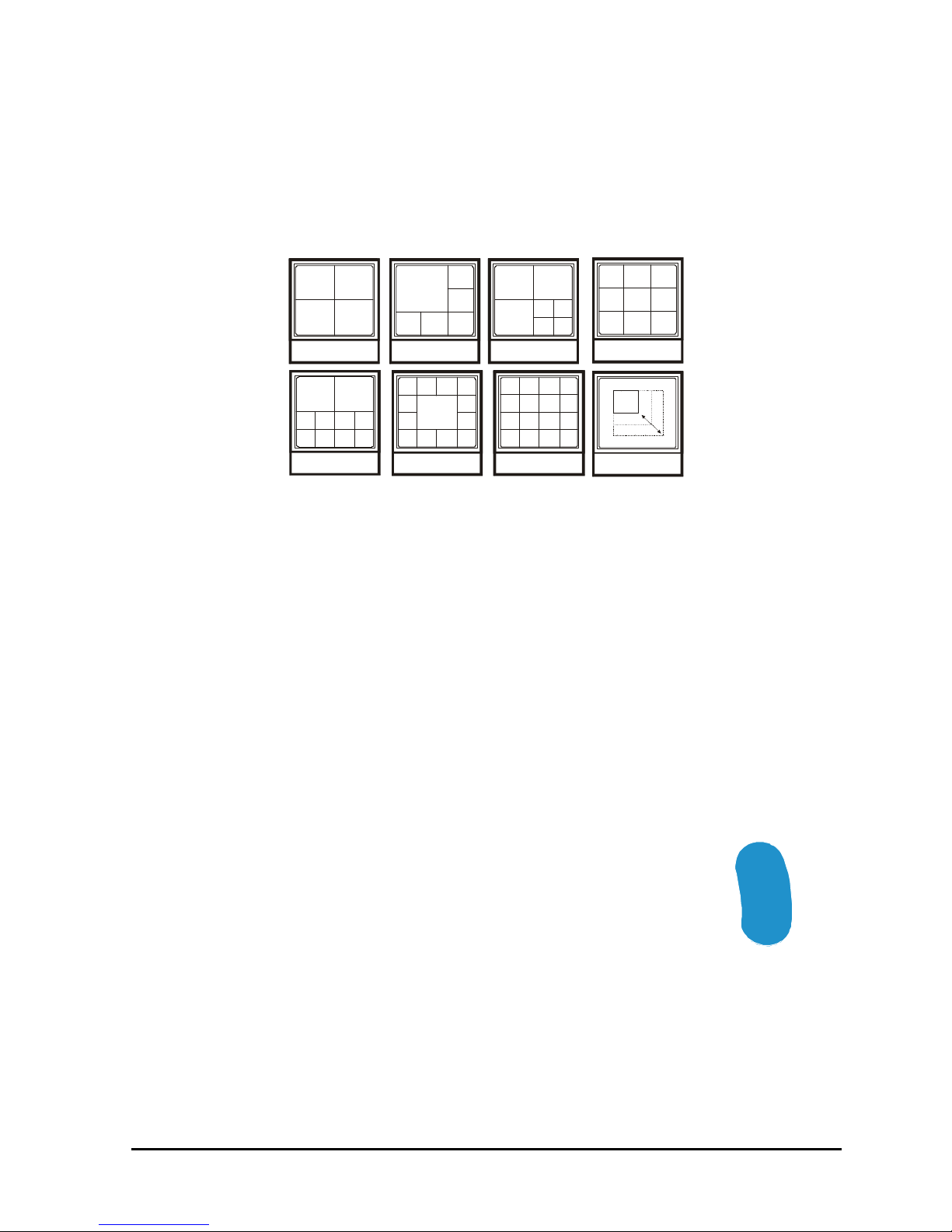
2.6 Display Options
Available Multiscreen Displays
Press the Multiscreen button to activate the multiscreen display. Repeatedly pressing the
Multiscreen button advances the display to the next multiscreen.
4-Way
10-Way
The multiscreen display is limited to the number of camera inputs on the unit.
Sixteen-Channel unit: Capable of displaying all multiscreens.
Ten-Channel unit: Only capable of displaying 10-way through 4-way multiscreen and PIP.
Four-Channel unit: Only capable of displaying 4-way and PIP.
The camera assignments for each multiscreen is retained (in non-volatile memory) for both Live and
Playback multiscreen mode on Monitor A, as well as Live multiscreen mode on Monitor B.
PIP: Use the Arrow Button to adjust the location and size of the PIP display. Please note that the PIP
display is only available on Monitor A in Live mode.
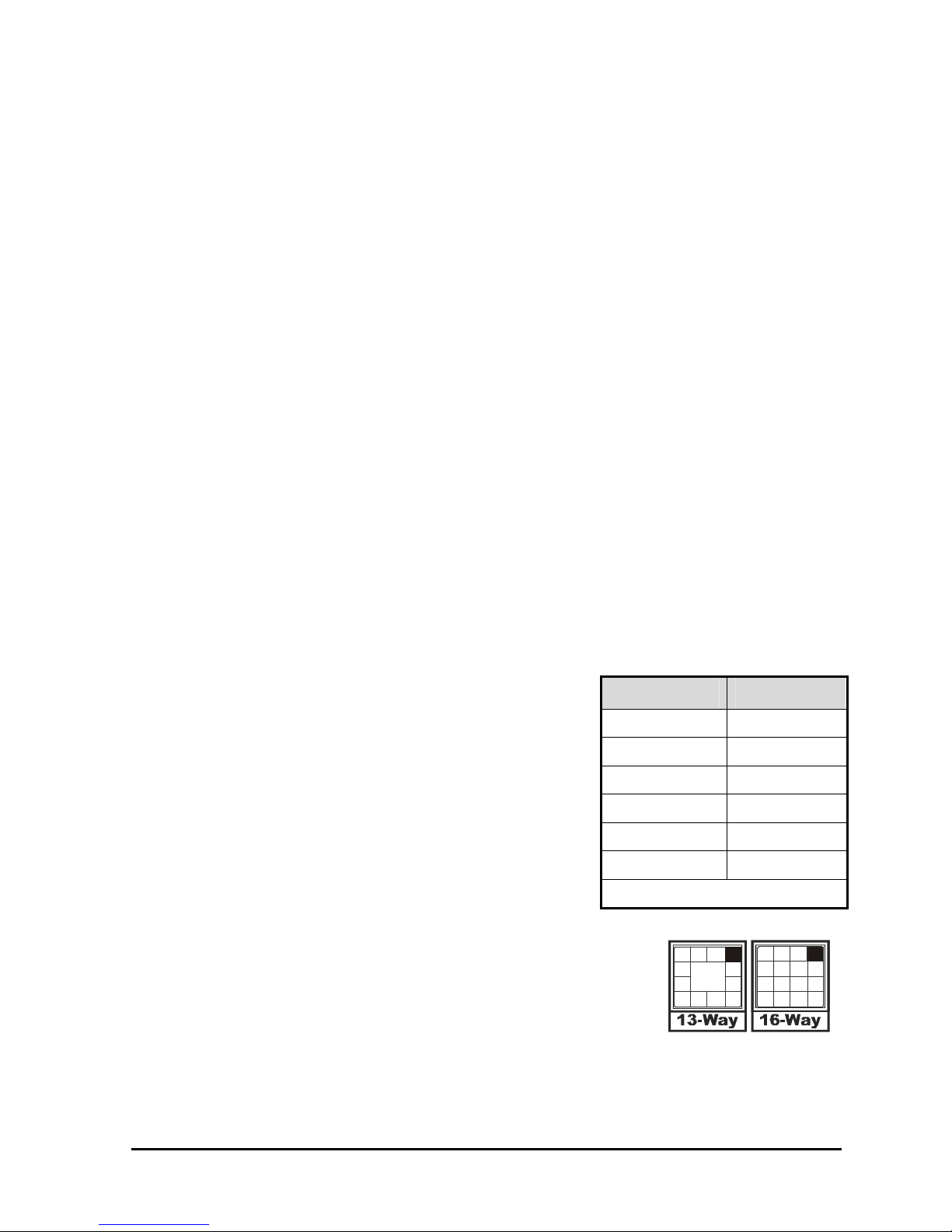
6-Way
13-Way
7-Way
9-Way
PIP
2.7 Active Cameos
A cameo is defined as any cell within a multiscreen display. Active Cameo mode allows the user to
access and edit each cameo individually.
Entering Active Cameo Mode
While viewing a multiscreen, enter Active Cameo mode by pressing the Enter
button. Active Cameo mode is indicated on-screen by flashing the number
and titles of the active cameo. By default, the top left cameo is activated.
0150-0202G 20 Vista Columbus Triplex
E
N
T
E
R
Enter Button

Selecting Cameos
Select a cameo using the Arrow Buttons to navigate the multiscreen.
Pressing the Up or Down arrow selects the next screen up or down a column.
Pressing the Right or Left arrow selects the next screen across a row. The
active cameo will always be indicated by the flashing camera number and
titles.
Arrow Buttons
Selecting Cameras
Display any camera in the active cameo by pressing the Number button of
the desired camera. Once a camera has been selected, the active cameo
advances to the next cameo on the right.
Number Button
The camera selection only changes the multiscreen currently being displayed. Each multiscreen must
be configured separately. Changes to the multiscreen display are saved in non-volatile memory, and
will be retained even if power is removed from the unit.
1
Freezing
Press the Freeze button to freeze the image in the selected cameo. Each
frozen cameo is indicated as * (a flashing asterisk) on-screen.
Press the Freeze button again to cancel Freeze operations.
Freeze Button
2.8 Sequencing
The sequencing feature allows a camera to be displayed briefly on-screen,
before advancing to the next camera in the sequence list. The default
sequence list displays each camera in numerical order.
Dwell Time
The dwell time is the amount of time each camera is displayed on-screen before advancing to the next
camera. The Multiscreen dwell time is fixed at 3 seconds. The default Fullscreen dwell time is also 3
seconds, but can be changed once an Autolist is programmed.
Autolist™ Custom Sequence List
The Autolist™ feature allows the user to create a custom sequence list, controlling the order the
cameras are displayed and the dwell time. Separate Autolists may be created for Monitor A (Live and
Playback mode) and Monitor B (Live mode). Using the Monitor button, select the monitor to be
programmed. Then, using a Number button, select any camera for full screen display.
NOTE
To begin recording the Autolist™ sequence: Press the Alarm button and
Sequence button simultaneously. Autolist Program mode is indicated as
PGM on-screen.
Recording starts when the first camera number is pressed. Press the camera
numbers in the order you wish them to appear on-screen. The amount of
time between button presses determines the Dwell Time. During sequence
list programming, pressing any button other than a Number button or the
Sequence button voids the sequence list.
The unit must be in Full Screen Display mode before starting to create the sequence list.
This initial camera is not part the sequence list.
Sequence Button
Alarm Button and
Sequence Button
0150-0202G 21 Vista Columbus Triplex
To end the recording: Press the Sequence button. The amount of time between pressing the last
Number button and the Sequence button determines the dwell time for the final camera in the
sequence list.
Sequencing In Cameos
While viewing a multiscreen display, additional cameras (cameras not shown in the multiscreen
display) can be sequenced in the lower right hand cameo by pressing the Sequence button. The
sequence list is not programmable. Press the Sequence button again to cancel sequencing.
2.9 On-screen Indicators
There are five types of on-screen indicators.
Camera Titles: Displays the camera number and the camera title.
Status Indicators: Displays Time, Date, and Hard Disk record time left.
Conditional Indicators: Displays indicators for Freeze, Zoom, Alarm, Motion Detection, Videoloss,
Autolist™ Program mode, Macro Record and Macro Playback mode.
Status Display Box: Displays Archive Device, Network status and Image Quality Setting (Playback
mode only).
Text Display Box: Displays ATM/POS Text data.
Camera Titles
Camera Titles are displayed on either the upper or lower corner of the left hand side of the screen.
The camera title can be changed in the menu system (see section 3.13). The user can change display
position and Colour. See below.
Changing Position And Colour Of Title And Status Indicators
Camera Titles: To change the colour and position of the camera
titles, select a camera for full screen display, then press the Enter
button to advance to the next display setting. Repeatedly pressing
the Enter button advances the display settings through the
sequence show in the table on the right.
Status Indicators & Camera Titles: Select Camera 1 for full
screen display. Using the Enter button, cycle through the
sequence shown on the right. Each time the position cycle is
completed, the unit advances the Status Indicator colour. Choose
Black, White or Grey.
Position Colour
Top Left Black
Top Left White
Top Left Grey
Bottom Left Black
Bottom Left White
Bottom Left Grey
Title not displayed
Status Indicators
Status indicators are displayed on the upper right hand corner of the
screen.
Status indicators include:
• Time and Date (these can be turned off in the menu system, see
section 3.8). The Time and Date format can also be changed in
the menu system.
• Time remaining on Hard Disk(s).
0150-0202G 22 Vista Columbus Triplex
Small Cameo

Conditional Indicators
Condition Full Screen Indicator Multiscreen Indicator
Alarm ALM A in cameo of camera in alarm
Autolist™ Program
mode
Freeze FRZ
Macro Record mode F followed by macro number F followed by macro number
Motion Detection M M in cameo w/ motion detection
Videoloss VDL V in cameo with videoloss
Zoom ZOOM ZOOM
PGM PGM
(Asterisk) in frozen cameo
*
Status Display Box
A Status Display Box can be viewed by pressing the Camera Number button twice. Status Indicators
include:
On Live Fullscreen:
• Archive Status: Not Connected, Not Ready, Ready, Ejecting, Play, and timeleft. Timeleft
indicates the amount of time before the archive medium is full (Only available if the unit has
Background Archiving turned On).
• Network: Displays all current Network connections. Normal connection is displayed as ip.ip or ---
if there is no connection. Live connections are displayed as E1: ip.ip, E2: ip.ip, etc. (where ip.ip
represents the last 2 bytes of the IP Address). POTS connection is displayed as IP 1.1.
On Playback Fullscreen:
• All the above, including Image Quality Setting: High, Medium, Standard.
ATM/POS Text Display
Pressing the Camera Number a third time displays an ATM/POS text display. This feature can be
used during live viewing mode to verify that the Columbus Triplex is receiving ATM/POS text, or in
Playback mode to review recorded text and video.
2.10 Triplex Mode
Triplex mode allows the display of both live and playback images to appear on Monitor A
simultaneously. Live images have grey borders, while playback images have black borders.
To enter Triplex mode, press the Play Forward button while in Play Forward mode. Alternatively, press
the Play Reverse button while in Play Reverse mode. Both the Play Forward LED and the Stop LED
turn on to indicate that the unit is in Triplex mode.
Play Forward
When in Play Forward mode and the Play Forward button is pressed, the unit will
enter the Triplex mode of operation. When Play Forward is pressed again, the
unit will revert back into the normal Playback mode. While in the Triplex mode, if
reverse play is in progress, the Play Forward button will change the playback
direction. The left and right arrows on the Arrow Buttons will also change the
playback direction when in triplex mode.
Play Forward
Button
0150-0202G 23 Vista Columbus Triplex

Reverse Play
When in Reverse Play mode and the Reverse Play button is pressed, the unit will
enter the Triplex mode of operation. When Reverse Play is pressed again, the
unit will revert back into the normal Playback mode. While in the Triplex mode, if
forward play is in progress, the Reverse Play button will change the playback
direction.
Fast Forward
During playback, press the Up Arrow button. The unit will display images at a
higher than normal rate. There are 4 Fast Forward rates. Repeated pressing of
the Up Arrow button will increase the playback speed.
Rewind
During playback, press the Down Arrow button. The unit will display images (in
reverse) at a higher than normal rate. There are 4 Rewind rates. Repeated
pressing of the Left Arrow button will increase the rewind speed.
Pause/Freeze
During playback, press the Freeze button. This feature pauses all full screen and
multiscreen images. Pause is indicated by FRZ on the playback monitor.
Single Frame Advance
While in Pause mode, press the Right Arrow button. The unit will advance a
single frame, then return to Pause mode.
Reverse Play
Button
Up Arrow
Button
Down Arrow
Button
Freeze Button
Single Frame Rewind
While in Pause mode, press the Reverse Play button. The unit will rewind a
single frame, then return to Pause mode.
Stop
To stop Triplex mode and return to Live mode on Monitor A, press the Stop
button.
0150-0202G 24 Vista Columbus Triplex
Right Arrow
Button
Left Arrow
Button
Stop Button
 Loading...