

Vista 5250 Installation Instructions Manual
5250
Lens Cover
Lens Cover
Landscape Series
In-Ground & Well Lights
INSTALLATION INSTRUCTIONS
FOR USE ONLY WITH LOW VOLTAGE LANDSCAPE POWER UNITS THAT DO NOT EXCEED 25 AMPS, 15 VOLT MAXIMUM.
WARNING: Luminaires must be installed in accordance with the National Electrical Code (NEC) and local codes. Failure to do so will void the warranty
and may result in serious injury and/or damage to the luminaire.
SAFETY WARNING: Luminaire can become very hot depending on lamp wattage used. Lens and metal around lamp can become hot enough to blister
hands. Particular care should be taken not to locate luminaires where small children can reach them if high wattage lamps are used.
WARNING: Debris must be kept clear from top and interior of ingrade fixtures. Excessive heat could occur that may create a fire hazard and/or harm
the fixture components. Specific attention must be made to never install ingrade fixtures in mulch, wood chips or other potentially ignitable materials.
For installation in potentially ignitable materials, such as mulch and wood chips, installer must use an above-grade mounted fixture. FAILURE TO DO
SO WILL VOID THE WARRANTY AND MAY RESULT IN SERIOUS INJURY AND/OR DAMAGE TO THE FIXTURE AND/OR PROPERTY.
LUMINAIRES ARE NOT TO BE INSTALLED WITHIN 10 FT. (3.05M) OF A POOL OR SPA. SECONDARY CABLE IS NOT TO BE BURIED MORE
THAN 6”. WHEN USING MULTIPLE LUMINAIRES, LOAD IS NOT TO EXCEED THE TOTAL WATTS OF TRANSFORMER RATING. DO NOT USE
EXTENSION CORDS ON POWER UNITS.
NOTE: Always use UL recognized wire connectors for connections.
NOTE: Save these instructions for future reference.
LUMINAIRE MOUNTING:
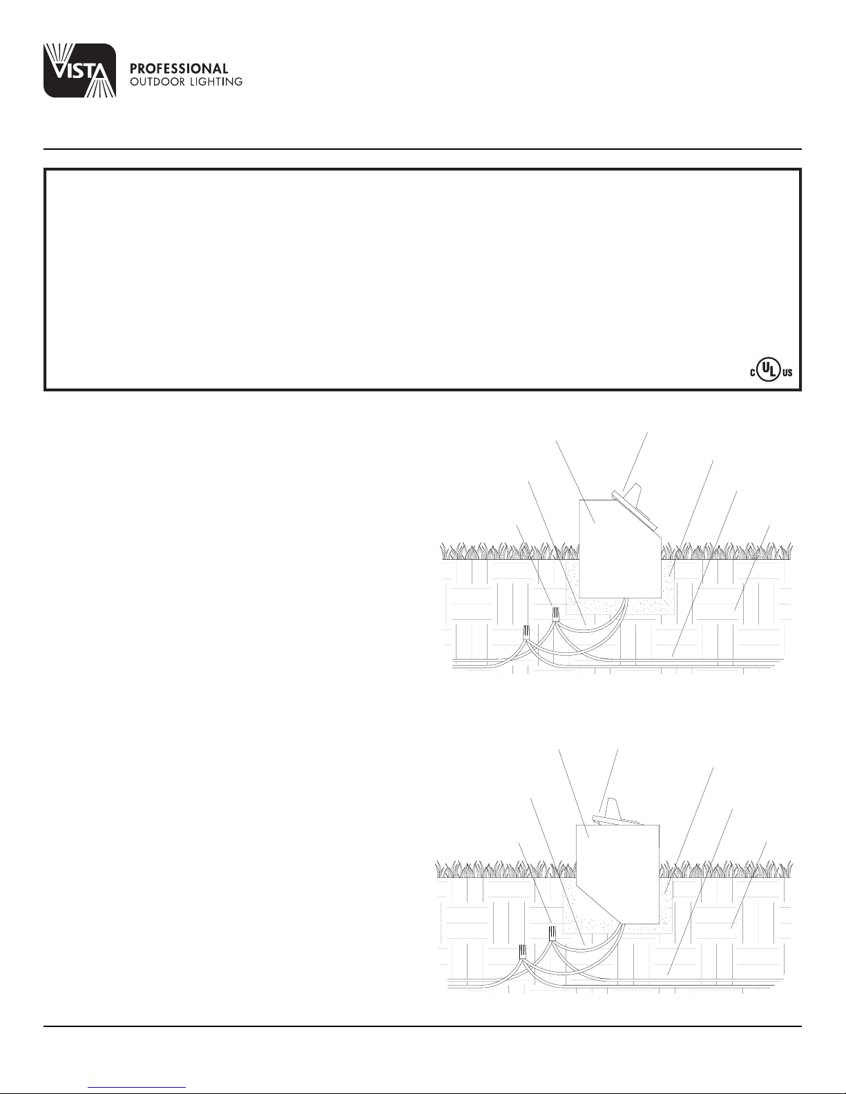
PRECAUTION: Luminaire is not submersible and adequate drainage
must be provided during installation. It is recommended the luminaire be
surrounded by 3” to 4” of pea gravel or sand to assure proper drainage.
Top of luminaire must be above grade so rain and irrigation water will not
accumulate for long periods of time.
1. To prevent electrical shock, disconnect transformer from electrical supply
before installation or service.
2. Dig hole approximately 12” diameter by 11” deep. This allows
approximately 3” of pea gravel or sand to surround the ABS sleeve.
NOTE: ABS sleeve is reversible. Straight cut end allows flush ground
mounting. Angle cut end requires the top three (3) inches to be installed
above ground for vertical aiming. See fig. 2
3. Place luminaire with support bracket inside ABS sleeve and adjust angle
with adjusting screw on side of support bracket. Push luminaire and support
bracket down to desired level.
4. Run wire pigtail through bottom of ABS sleeve and strip the two (2) leads
from the luminaire wire. Using the two (2) silicone filled safety connectors
(provided), connect the leads from the luminaire to the main supply cable
leads.
NOTE: Luminaires are supplied with 36” of 18-2 cable pigtail for secure
connection to the main supply cable. The wire is to be protected by routing
in close proximity to the luminaire. The wiring should be buried a maximum
depth of 6 inches (15.2 cm) in order to connect to the main supply cable.
4. Backfill hole after installation with pea gravel or sand.
5. Provide power to the luminaire and check for proper operation.
36” Pigtail
Silicone Filled
Safety Connectors
fig. 2
36” Pigtail
Silicone Filled
Safety Connectors
ABS Well
Gravel/Sand
Main Supply
Cable
Soil
ABS Well
Gravel/Sand
Main Supply
Cable
Soil
Vista Professional Outdoor Lighting reserves the right to modify the design and/or construction of the fixture shown without further notification.
1625 Surveyor Avenue • Simi Valley, CA 93063 • (805) 527-0987 • (800) 766-VISTA (8478)
FAX: (888) 670-VISTA (8478) • email@vistapro.com • www.vistapro.com
INSTALLATION INSTRUCTIONS
IMPORTANT SAFETY INSTRUCTIONS - THE LIGHTED LAMP IS HOT!
WARNING: TO REDUCE THE RISK OF FIRE, OR INJURY TO PERSONS:
1. Turn off/unplug and allow to cool before replacing lamp.
2. Lamps get hot quickly! Contact only switch/plug when turning on.
3. Do not touch hot lens, guard or enclosure.
SAVE THESE INSTRUCTIONS
(Leave with property owner/manager)
5250
Landscape Series
In-Ground & Well Lights
4. Keep lamp away from material that may burn.
5. Do not touch the lamp at any time. Use a soft cloth. Oil from the skin
may damage lamp.
6. Do not operate luminaire fitting with a missing or damaged cover.
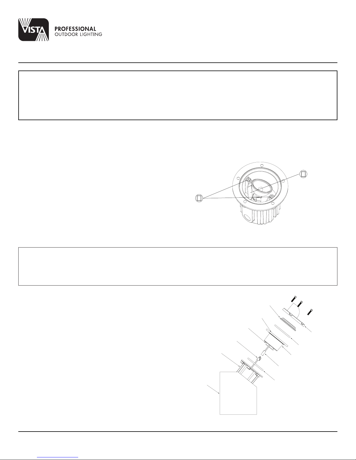
LAMP INSTALLATION/REPLACEMENT:
NOTE: Lamp bracket may be adjusted for lamp aiming.
Loosen bracket screws (1), then manually tilt bracket (2) to desired position.
CAUTION: Do not exceed maximum wattage marked on luminaire label.
1. To prevent electrical shock, disconnect transformer from electrical supply
Tighten bracket screws afterward to secure lamp position.
6. Re-install cover and tighten the cover screws evenly.
before service.
2. Loosen cover screws and remove cover.
3. Remove gasket.
4. Replace lamp with correct wattage and type marked on fixture label.
NOTE: DO NOT touch Halogen lamp with bare hands. Always use soft
2
cloth or the plastic wrapping (if available) from the lamp to handle the lamp.
5. Clean gasket channel and re-install a new gasket.
NOTE: As a recommended practice for installers of all ingrade luminaires,
Vista strongly recommends replacing the gasket with a new one each time
1
the fixture is unsealed for maintenance. A replacement gasket for future use
is provided for your convenience. Additional gaskets for your maintenance
kit may be purchased through your local Vista Professional Outdoor
Lighting distributor.
LED:
The operating voltage range for this LED luminaire is 10.5 - 15 volt AC. The Vista electronic driver ensures the LED operates at the intended lumen
output while receiving voltage as low as 6 volts, and as high as 15 VAC, resulting in a balanced lumen output from the first fixture to the last. Eliminating
the dimness issues often attributed to voltage drop.
Note: Operating voltage range for LED luminaries will vary depending on model, style and total number of LEDs. To help determine the operating
voltage range for each Vista luminaire, always consult factory’s specification sheet and/or installation instructions before installation.
LED ENGINE INSTALLATION/REPLACEMENT:
1. To prevent electrical shock, disconnect transformer from electrical supply
before service.
2. Loosen cover screws and remove cover.
3. Remove upper silicone O-ring.
4. Pull field replaceable LED engine assembly out.
5. Disconnect Connector Assembly, inspect & clean lower silicone O-ring.
6. Connect new field replaceable LED engine to connector assembly.
7. Reinstall LED engine.
8. Clean gasket channel and reinstall a new upper silicone O-ring.
NOTE: As a recommended practice for installers of all ingrade luminaries,
Vista strongly recommends replacing the gasket with a new one each time
the fixture is unsealed for maintenance. A replacement gasket for future use
is provided for your convenience. Additional gaskets for your maintenance
kit may be purchased through your local Vista Professional Outdoor
Lighting distributor.
9. Reinstall cover and tighten the cover screws evenly.
FIELD REPLACEABLE DRIVER
MALE CONNECTOR
FIXTURE HOUSING
ABS HOUSING
CONVEX LENS
PROTECTIVE
TEMPERED LENS
SILICONE O-RING
FIELD REPLACEABLE
LED ENGINE
FEMALE CONNECTOR
SILICONE O-RING
FIXTURE COVER
Vista Professional Outdoor Lighting reserves the right to modify the design and/or construction of the fixture shown without further notification.
1625 Surveyor Avenue • Simi Valley, CA 93063 • (805) 527-0987 • (800) 766-VISTA (8478)
FAX: (888) 670-VISTA (8478) • email@vistapro.com • www.vistapro.com
5250 11.15
 Loading...