

VISTA 50p Diagram

VISTA-50P
Features Q.E.D. programming for
quick enrollment of devices.
VISTA-50PUL
PARTITIONED SECURITY SYSTEM
with SCHEDULING
Quick Start
Step-by-Step Programming Procedure
Single And Multiple Partition Programming Forms
System Worksheets
VISTA50P-PR 8/95 (See Instructions N5944-6)

Ð 2Ð

TABLE OF CONTENTS
SUMMARY OF PROGRAMMING COMMANDS ....................................................................................... 2
RECOMMENDED PROGRAMMING PROCEDURE................................................................................. 3
PROGRAM FIELD CATEGORIES............................................................................................................. 5
VISTA-50P/PUL SINGLE PARTITION PROGRAMMING FORM.............................................................. 6
VISTA-50P/PUL MULTIPLE-PARTITION PROGRAMMING FORM....................................................... 11
PROGRAMMING WITH #93 MENU MODE............................................................................................. 17
SYSTEM LAYOUT WORKSHEETS........................................................................................................ 18
The purpose of this document is to provide a quick and easy way to program your entire system. A
recommended programming procedure is included, followed by a list of program fields with the
corresponding program group they belong to (system-wide, partition-specific, scheduling, etc.). Two
program forms are included, one for a single-partition system, and the other for a multiple partition system.
If you are setting up a single-partition system, the partition-specific fields become system-wide fields.
Following the program forms are system layout worksheets. We recommend that you use these sheets
to plan your system before programming is performed. If you need further information about specific
programming options, see the VISTA-50P/VISTA-50PUL INSTALLATION INSTRUCTIONS.
Two programming forms are provided: Single Partition Form and Multiple-Partition Form
• Make sure that one two-line alpha keypad is connected to the control and is set to device
address "00."
Single Partition System
• The system default is for a single partition system. Use the VISTA-50P/PUL SINGLE
PARTITION PROGRAMMING FORM beginning on page 7 when programming for single
partition usage. Follow the steps outlined on page 4 of this document for proper programming
procedure.
Multiple-Partition System
• You must enter the number of partitions you are using in data field 2*00 to set the system for
multiple partitions. Use the VISTA-50P/PUL MULTIPLE-PARTITION PROGRAMMING FORM
beginning on page 13 when programming the system for multiple partitions. Follow the steps
outlined on page 4 of this document for proper programming procedure.
SUMMARY OF PROGRAMMING COMMANDS
¥ To enter program mode, enter installer code + [8] + [0] + [0]
¥ To set standard defaults, press *97
¥ To set communication defaults, press *94 + one of the following: *80=low speed; *81=Ademco
Express; *82=Ademco High Speed; *83=Ademco's Contact ID
¥ To change to next page of program fields, press *94
¥ To return to previous set of fields, press *99
¥ To erase account & phone number field entries, press [*] + field number + [*]
¥ To assign zone descriptors, press #93 + follow menu prompts
¥ To add custom words, press #93 + follow menu prompts
¥ To enter Installer's Message, press #93 + follow menu prompts
¥ To exit program mode, press *99 OR *98: *99 allows re-access to programming mode by installer code.
*98 prevents re-access to programming mode by installer code.
Standard default (*97) values are shown in brackets [ ], otherwise default = 0.
Ð 3 Ð

Recommended Programming Procedure
The following is a step-by-step procedure recommended for programming
your VISTA-50P/VISTA-50PUL system.
1 . Set the keypads (and other peripheral devices) to the
appropriate addresses.
2 . Set factory defaults by pressing *97.
This will automatically enable keypad addresses 00-03, so be sure at least
one keypad is set to one of these addresses.
3 . Program system-wide (global) data fields.
Using the programming form as a guide, enter program mode and program
all system wide programming fields. These options affect the entire
system, regardless of partitions. They include control options, downloader
and dialer options, RF options, event logging options, etc. Refer to the
COMPLETE LIST OF PROGRAMMING FIELDS for a listing of the program
fields arranged by function.
Note that field 2*00 (number of partitions) & field 1*32 (RF
expander type) must be programmed before continuing.
4 . Program partition-specific fields.
When the system-wide fields have been programmed, program all
partition-specific programming fields by first pressing *91 to select a
partition (while still in data field program mode). Then enter the first
partition-specific field number *09. The next partition-specific field will
automatically be displayed when you are finished entering the value for
field *09. Partition-specific fields can have different values for each
partition. To program the fields for the next partition, press *91, enter the
desired partition number, then enter field *09. Refer to the MECHANICS
OF PROGRAMMING section for detailed instructions.
5 . Use #93 Menu Mode for device programming.
Refer to the DEVICE PROGRAMMING section to assign keypad ID
numbers and default partitions for each keypad, and to selectively
suppress certain keypad sounding options. Also use this mode to assign
RF receivers, relay modules, and the VIP module.
6 . Use #93 Menu Mode for zone programming.
Refer to the ZONE PROGRAMMING section to program zone response
types, assign right loop zones and wireless zones, assign zones to
partitions, and to program alarm report codes.
Ð 4Ð
8 . Use #93 Menu Mode for programming relays.
Refer to the RELAY PROGRAMMING section to program desired relay
operation.
9 . Program Communication options.
Refer to the COMMUNICATION PROGRAMMING section for further
instructions to load communication defaults and to program related fields.
1 0 . Use #93 Menu Mode for programming alpha descriptors.
Refer to the ALPHA PROGRAMMING section to enter zone and partition
descriptors and a custom installer's message.

1 1 . Use #93 Menu Mode for programming relay voice descriptors
and custom word substitutes.
Refer to the RELAY VOICE DESCRIPTORS section for further instructions
for programming relay descriptors to be annunciated by the 4285 VIP
module, as well as the CUSTOM INDEX section for custom word
substitutes.
12. Use #80 Mode for programming schedules.
Refer to the SCHEDULING section to program open/close schedules,
temporary and holiday schedules, limitation of access schedules, and time
driven events.
1 3 . Define user access codes.
Refer to SECURITY ACCESS CODES section to program authority level,
O/C reporting option, partition assignments, and wireless key assignments
for each user.
1 4 . Exit Programming Mode
Exit programming mode by pressing either *98 or *99. A second entry of
*99 is required if the exit is being done from fields 1*00 and above.
To prevent re-access to Programming mode using the Installer's code, use
*98. The only way to re-access Programming mode is by depressing both
the [*] and [#] keys at the same time within 30 seconds of power up.
Exiting by using *99 always allows reentry into Programming mode using
the Installer's code. Either way of exiting will allow access via downloading.
Note that if local programming lockout is set via downloading, programming
mode cannot be entered at the keypad.
Ð 5 Ð

PROGRAM FIELD CATEGORIES
In the following pages, the programming fields have been arranged by category. Use this index to cross reference
the numerical ordered fields on the programming form.
Field Group
*0 0 System-Wide
*0 2 #93 Menu Mode
*0 3 #93 Menu Mode
*0 4 #93 Menu Mode
*0 5 #93 Menu Mode
*0 9 Partition-Specific
*1 0 Partition-Specific
*1 1 Partition-Specific
*1 2 Partition-Specific
*1 3 Partition-Specific
*1 4 System-Wide
*1 5 System-Wide
*1 6 Partition-Specific
*1 7 System-Wide
*1 8 System-Wide
*1 9 System-Wide
*2 0 System-Wide
*2 1 System-Wide
*2 2 Partition-Specific
*2 3 Partition-Specific
*2 4 System-Wide
*2 5 System-Wide
*2 6 Communications
*2 7 Communications
*2 8 System-Wide
*2 9 Partition-Specific
*3 0 Communications
*3 1 Communications
*3 2 Partition-Specific
*3 3 Communications
*3 4 Communications
*3 5 System-Wide
*3 6 System-Wide
*3 7 System-Wide
*3 8 Partition-Specific
*3 9 Partition-Specific
*4 0 Communications
*4 1 System-Wide
*4 2 Communications
*4 3 Communications
*4 4 Communications
*4 5 Communications
*4 6 Communications
*4 7 Communications
*4 8 Communications
*4 9 Communications
*5 0 Communications
*5 1 Communications
*5 2 Communications
*5 3 Communications
*5 4 Communications
*5 5 Communications
*5 6 Communications
*5 7 Communications
*5 8 Communications
*5 9 Communications
*6 0 Communications
*6 1 Communications
*6 2 Communications
Field Group
*6 3 Communications
*6 4 Communications
*6 5 Communications
*6 6 Communications
*6 7 Communications
*6 8 Communications
*6 9 Communications
*7 0 Communications
*7 1 Communications
*7 2 Communications
*7 3 Communications
*7 4 Communications
*7 5 Communications
*7 6 Communications
*7 7 Communications
*7 8 Communications
*7 9 Communications
*8 0 Communications
*8 1 Communications
*8 2 Communications
*8 3 Communications
*8 4 Partition-Specific
*8 5 Partition-Specific
*8 7 Partition-Specific
*8 8 Partition-Specific
*8 9 Communications
*9 0 Partition-Specific
1*01 #93 Menu Mode
1*02 #93 Menu Mode
1*03 #93 Menu Mode
1*04 #93 Menu Mode
1*05 #93 Menu Mode
1*06 #93 Menu Mode
1*07 #93 Menu Mode
1*08 #93 Menu Mode
1*09 #93 Menu Mode
1*17 System-Wide
1*18 Partition-Specific
1*19 Partition-Specific
1*20 System-Wide
1*21 System-Wide
1*22 System-Wide
1*23 System-Wide
1*24 System-Wide
1*25 System-Wide
1*28 System-Wide
1*29 System-Wide
1*30 System-Wide
1*31 System-Wide
1*32 System-Wide
1*33 Communications
1*34 Communications
1*35 Communications
1*36 Communications
1*37 Communications
1*38 Communications
1*39 Communications
1*40 Communications
1*41 Communications
1*42 Communications
1*43 Partition-Specific
1*44 System-Wide
1*45 Partition-Specific
1*46 System-Wide
1*47 Partition-Specific
1*48 System-Wide
1*49 System-Wide
1*52 Partition-Specific
1*53 System-Wide
1*57 System-Wide
1*58 System-Wide
1*60 System-Wide
1*70 System-Wide
1*71 System-Wide
1*72 System-Wide
1*73 System-Wide
1*74 System-Wide
1*75 System-Wide
1*76 Partition-Specific
2*00 System-Wide
2*01 System-Wide
2*02 System-Wide
2*05 Partition-Specific
2*06 Partition-Specific
2*07 Partition-Specific
2*08 Partition-Specific
2*09 Partition-Specific
2*10 Partition-Specific
2*11 System-Wide
2*13 Communications
2*14 Communications
2*18 Partition-Specific
2*19 Partitioning
2*20 Partition-Specific
2*21 System-Wide
Ð 6Ð
VISTA 50P/VISTA 50-PUL
SINGLE PARTITION PROGRAMMING FORM
Standard default (*97) values are shown in brackets [ ], otherwise default = 0. Fields bordered by dotted line can be
programmed using the #93 Menu mode.
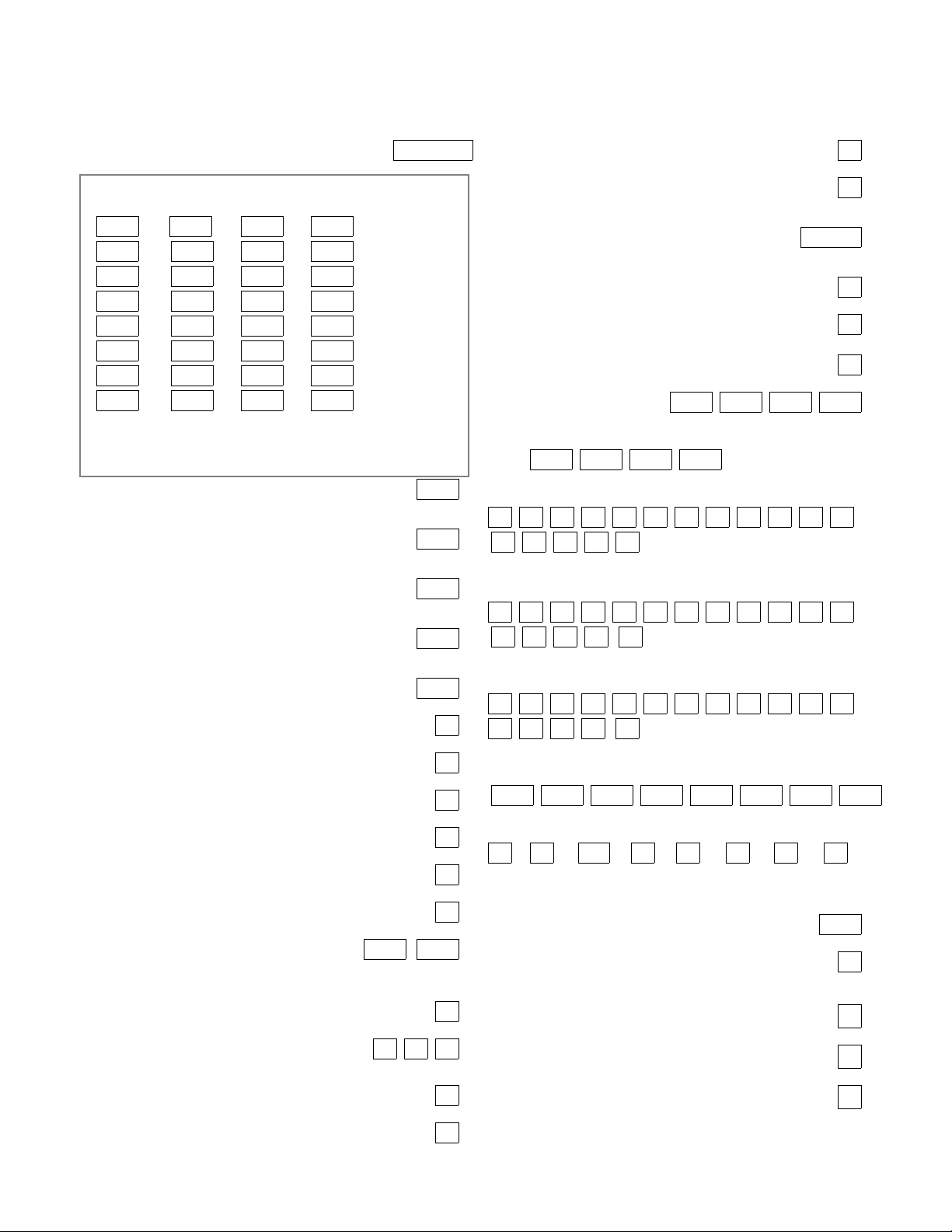
*00 INSTALLER CODE | | |
Enter 4 digits, 0-9 [4140]
ASSIGN RESPONSE TYPE FOR ZONES 1-27, 95-99
(Enter 00-10) see fields 1*01-1*09 for response types for zones 28-87.
*02 *03 *04 *05
1 | 9 | 17 | 25 |
2 | 10 | 18 | 26 |
3 | 11 | 19 | 27 |
4 | 12 | 20 | 0|0
5 | 13 | 21 | 97 | polling loop short
6 | 14 | 22 | 95 | (1+Q panic)
7 | 15 | 23 | 96 | (3+ # panic)
8 | 16 | 24 | 99 | (Q+ # panic)
RESPONSE TYPES: 00 = Disabled zone; 01 = Entry/Exit #1;
02 = Entry/Exit #2; 03 = Perimeter; 04 = Interior Follower;
05 = Day/Night; 06 = 24 hour Silent Alarm; 07 = 24 hour Audible Alarm;
08 = 24 hour Auxiliary; 09 = Fire; 10 = Interior, Delay; 20 = arm stay;
21 = arm away; 22 = disarm; 23= no alarm response
*09 ENTRY DELAY #1 [02] |
00-15 times 15 seconds
Maximum 3 for UL Listed installations.
*10 EXIT DELAY #1 [03] |
00-15 times 15 seconds
Maximum 4 for UL Listed installations.
*11 ENTRY DELAY #2 [06] |
00-15 times 15 seconds
Maximum 3 for UL Listed installations.
*12 EXIT DELAY #2 [08] |
00-15 times 15 seconds
Maximum 4 for UL Listed installations.
*13 ALARM SOUNDER DURATION [04] |
01-15 times 2 minutes. Minimum 4 minutes for UL.
*14 ZONE 9 RESPONSE TIME [0]
1=fast; 0= normal; "0" for UL.
*15 KEYSWITCH ASSIGNMENT [0]
Enter partition in which keyswitch used, 1-8; 0=disable
*16 CONFIRMATION OF ARMING DING [0]
1=enable; 0=disable
*17 AC LOSS KEYPAD SOUNDING [0]
1=yes; 0=no
*18 UL AC LOSS SIREN [0]
1=yes; 0=no
*19 RANDOMIZE AC LOSS REPORT [0]
1=randomize 10-40 min.; 0=no
*20 VOICE MODULE PHONE CODE [00] | |
Enter 01-09 for 1st digit; 11 (for *) or 12 (for #) for 2nd digit.
To disable voice module, enter 1st digit = 00 & 2nd digit = 11
Must be disabled for UL Listed installations.
*21 PREVENT FIRE TIME-OUT [0]
1=no timeout; 0=fire timeout
*22 KEYPAD PANIC ENABLES [001]
1=enable; 0=disable 95 96 99
*23 MULTIPLE ALARMS [1]
1=yes; 0=no
*25 BURG.TRIGGER FOR RESPONSE TYPE 8 [1]
1=enable; 0=disable
*26 INTELLIGENT TEST REPORTING [0]
Set "0" for UL 1=yes, (no report sent if any other report
was recently sent); 0=no
*27 TEST REPORT INTERVAL [024] | |
Enter interval in hours, 001-999; 000=no report ; Max. 024
for UL.
*28 POWER UP IN PREVIOUS STATE [1]
1=yes; 0=no; "1" for UL.
*29 QUICK ARM [1]
1=yes; 0=no
*30 TOUCH-TONE OR ROTARY DIAL [0]
1=TouchTone; 0=rotary
*31 PABX ACCESS CODE | | | |
00-09; B-F (11-15)
*32 PRIMARY SUBSCRIBER ACCT #
|
| | |
Enter 00-09; B-F (11-15) [15 15 15 15]
*33 PRIMARY PHONE NUMBER
Enter 0-9 for each digit; enter #11 for *, #12 for #, and #13 for
2 sec. pause
*34 SECONDARY PHONE NUMBER
Enter 0-9 for each digit; enter #11 for *, #12 for #, and #13 for
2 sec. pause
*35 DOWNLOAD PHONE No.
Enter 0-9 for each digit; enter #11 for *, #12 for #, and #13 for
2 sec. pause
*36 DOWNLOAD ID No.
|
Enter 00-09; A-F (10-15) [15 15 15 15 15 15 15 15]
| | | | | | |
*37 DOWNLOAD COMMAND ENABLES
0
Dialer System Not Remote Remote Remote Upload Download
Shutdwn Shutdwn Used Bypass Disarm Arm Program Program
See field 1*53 for Callback disable option; [1=enable]; 0=disable; For UL
installations, all options must be disabled.
*38 PREVENT ZONE XX BYPASS [00] |
01-86; 00 if all zones (except Fire zones) can be bypassed
*39 ENABLE OPEN/CLOSE REPORT [0]
FOR INSTALLER CODE
1=enable; 0=disable
*40 OPEN/CLOSE REPORT FOR KEYSWITCH [0]
1=enable; 0=disable
*41 NORMALLY CLOSED or EOLR (Zones 2-8) [1]
1=N.C.loops; 0=EOLR supervision; Must be "0" for UL.
*42 DIAL TONE PAUSE [0]
0=5 seconds; 1=11 seconds; 2=30 seconds; Must be "0" for UL.
*24 IGNORE EXPANSION ZONE TAMPER [0]
1=yes; 0=enable for RF and RPMs
Ð 7 Ð
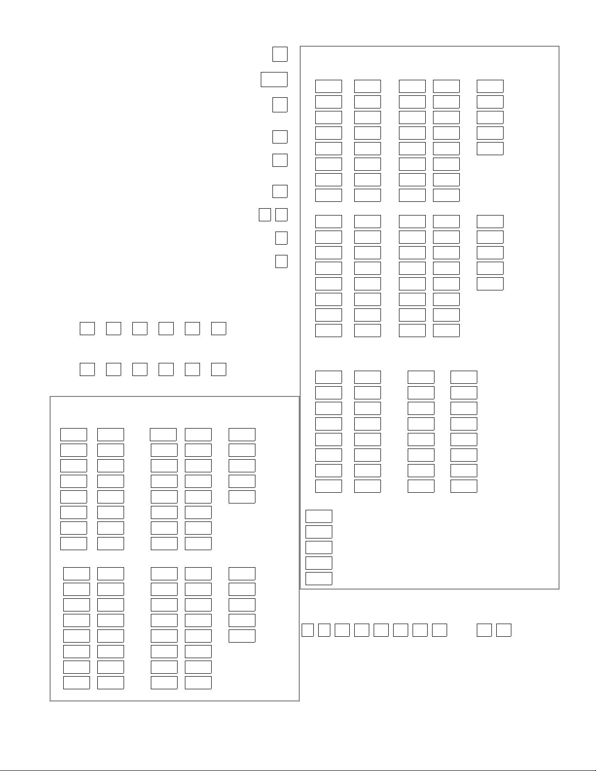
*43 DIAL TONE DETECTION [1]
1=wait for true dial tone; 0=pause, then dial
*44 RING DETECTION COUNT [00]
01-14; 15=answering machine; 00=no detection
*45 PRIMARY FORMAT [0]
0=Low Speed; 1=Contact ID; 2=Ademco High Speed;
3=Ademco Express
|
*46 LOW SPEED FORMAT (Primary) [0]
0=Ademco Low Speed; 1=Sescoa/Radionics
*47 SECONDARY FORMAT [0]
0=Low Speed; 1=Contact ID; 2=Ademco High Speed;
3=Ademco Express
*48 LOW SPEED FORMAT (Sec.) [0]
0=Ademco Low Speed; 1=Sescoa/Radionics
*49 CHECKSUM VERIFICATION [0] [0]
1=yes; 0=no PrimScndry
*50 SESCOA/RADIONICS SELECT [0]
1=Sescoa; 0=Radionics
*51 DUAL REPORTING [0]
1=yes; 0=no If used with Spilt Reporting "1" option (1*34),
alarms go to both primary & secondary numbers, while all other
reports go to secondary only. If used with Split Reporting "2"
option, alarms go to both, open/close and test messages go to
secondary only, while all other reports go to primary.
*52 STANDARD/EXPANDED REPORT (PRIMARY)
[0]
Alarm Rstr Bypass Trbl Opn/Cls Low Bat
0=standard; 1=expanded; Note: Expanded overrides 4+2 format
*53 STANDARD/EXPANDED REPORT (SECONDARY)
[0]
Alarm Rstr Bypass Trbl Opn/Cls Low Bat
0=standard; 1=expanded; Note: Expanded overrides 4+2 format
ALARM REPORT CODE & ID DIGITS FOR ZONES 1-32 &
SUPV. & RESTORE CODES [All codes default to 00]
*54 CODE *55 ID *56 CODE *57 ID *58
1 | | 9 | | | Alarm Rst.
2 | | 10 | | | Trouble
3 | | 11 | | | Trble Rst.
4 | | 12 | | | Bypass
5 | | 13 | | | Bypss Rst.
6 | | 14 | |
7 | | 15 | |
8 | | 16 | |
*59 CODE *60 ID *61 CODE*62 ID *63
17 | | 25 | | | Alarm Rst.
18 | | 26 | | | Trouble
19 | | 27 | | | Trble Rst.
20 | | 28 | | | Bypass
21 | | 29 | | | Bypss Rst.
22 | | 30 | |
23 | | 31 | |
24 | | 32 | |
ALARM REPORT CODE & ID DIGITS FOR ZONES 33-64 &
SUPV. & RESTORE CODES [All codes default to 00]
*64 CODE *65 ID *66 CODE*67 ID *68
33 | | 41 | | | Alarm Rst.
34 | | 42 | | | Trouble
35 | | 43 | | | Trble Rst.
36 | | 44 | | | Bypass
37 | | 45 | | | Bypss Rst.
38 | | 46 | |
39 | | 47 | |
40 | | 48 | |
*69 CODE *70 ID *71 CODE *72 ID *73
49 | | 57 | | | Alarm Rst.
50 | | 58 | | | Trouble
51 | | 59 | | | Trble Rst.
52 | | 60 | | | Bypass
53 | | 61 | | | Bypss Rst.
54 | | 62 | |
55 | | 63 | |
56 | | 64 | |
ALARM REPORT CODE & ID DIGITS FOR ZONES 81-87, RF
RCVRs & PANICS, & THEIR SUPV. & RESTORE CODES
*74 CODE *75 ID *76 CODE *77 ID [All codes default=00]
81 | | 89 | |
82 | | 90 | |
83 | | 91 | |
84 | | | | Duress
85 | | 97 | | Poll loop short
86 | | 95 | | (panic key 1+*)
87 | | 96 | | ( panic key 3+#)
88 | | 99 | | ( panic key * + #)
*78
| Alarm Rst.
| Trouble
| Trble Rst.
| Bypass
| Bypss Rst.
ZONE TYPE RESTORE ENABLES
1=enable; [0=disable]
NOTES: 97= Poll Loop Short; 88 & 90 = RCVR not
receiving transmitter signals. 89 & 91 = RCVR not
responding, bad conn. to panel. 87 = Voice Module
supervision.
*79 FOR ZONE TYPES 1-8 *80 FOR TYPES 9/10
12345 678 910
Ð 8 Ð
SYSTEM NON ALARM CODES
*81 *82
First Digit Second Digit
Close | |
Open | |
Low Battery | |
Low Bat Res | |
AC Loss | |
AC Restore | |
Test | |
Power | |
Cancel | |
Prog. Tamp. | |
*83 FIRST TEST REPORT TIME | | |
[Day 00; hour 12; min 00] Days 01-07 Hours 00-23 Min 00-59;
00 in all boxes=instant (Day 01= Monday)
*84 SWINGER SUPPRESSION [15] |
01-15 alarms; Must be "00" (disabled) for UL.
*85 ENABLE DIALER REPORTS [0]
FOR PANICS & DURESS 95 96 99 Duress
1=enable; 0=disable
*87 ENTRY WARNING [1]
1=continuous; 0=3 beeps
*88 BURG. ALARM COMM. DELAY [0]
1=16 seconds; 0=no delay
*89 RESTORE REPORT TIMING [0]
0=instant; 1=at bell timeout; 2=at disarm
*90 SECONDARY SUBSCRIBER ACCT #
|
| | |
Enter 00-09; B-F (11-15) [15 15 15 15]
Second digit of each code
applies only to 4+2 or
expanded (fields *52 &
*53) formats.
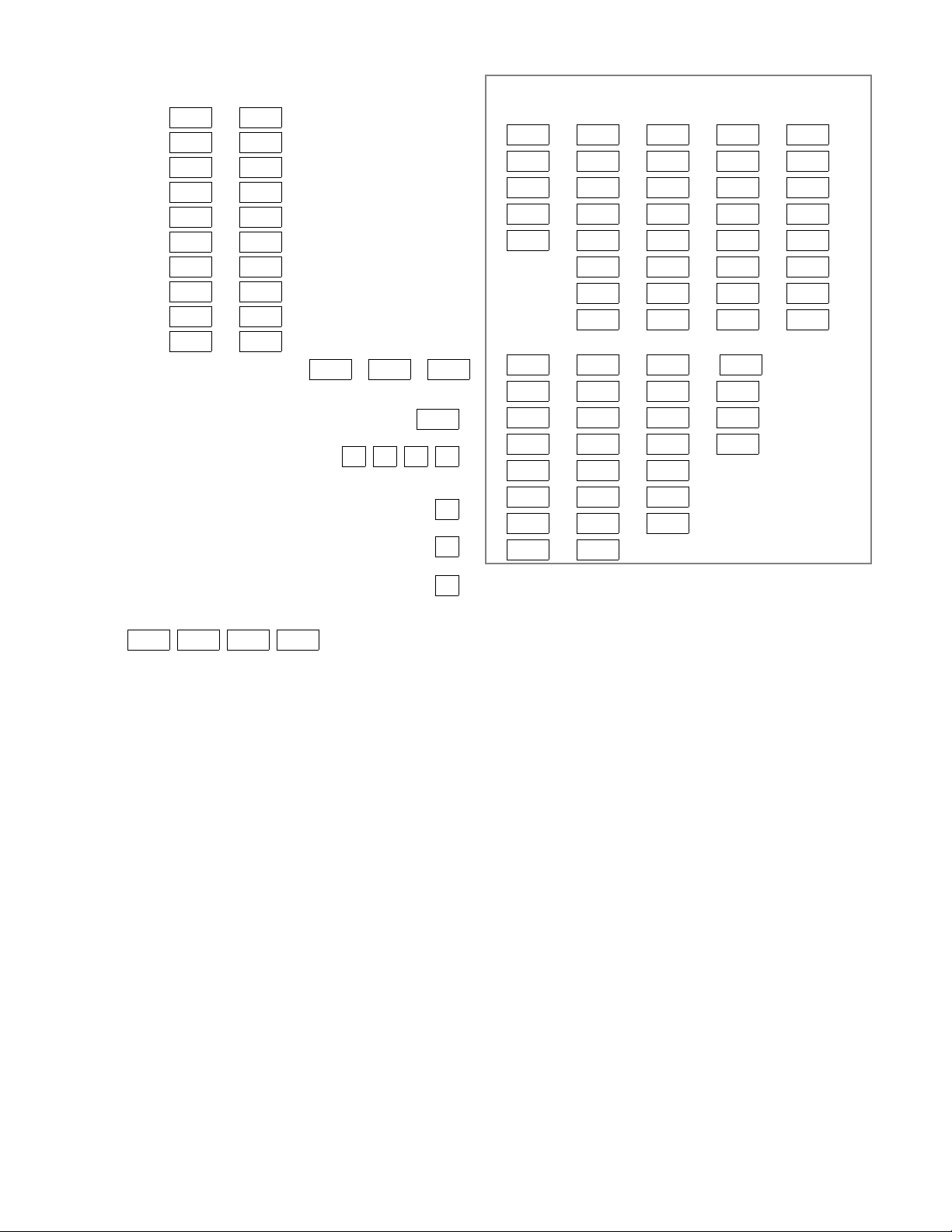
2nd Page Programming Fields (press *94)
ASSIGN RESPONSE TYPE FOR ZONES
(Enter 00-10; see Response Types below)
1*01 1*02 1*03 1*04 1*05
28 | 33 | 41 | 49 | 57 |
29 | 34 | 42 | 50 | 58 |
30 | 35 | 43 | 51 | 59 |
31 | 36 | 44 | 52 | 60 |
32 | 37 | 45 | 53 | 61 |
38 | 46 | 54 | 62 |
39 | 47 | 55 | 63 |
40 | 48 | 56 | 64 |
1*06 1*07 1*08 1*09
65 | 73 | 81 | 88 | 2nd RCVR
66 | 74 | 82 | 89 | 2nd RCVR
67 | 75 | 83 | 90 | 1st RCVR
68 | 76 | 84 | 91 | 1st RCVR
69 | 77 | 85 |
70 | 78 | 86 |
71 | 79 | 87 | Voice Module
72 | 80 |
RESPONSE TYPES: 00 = Disabled zone; 01 = Entry/Exit #1; 02 =
Entry/Exit #2; 03 = Perimeter; 04 = Interior Follower; 05 = Day/Night;
06 = 24 hour Silent Alarm; 07 = 24 hour Audible Alarm; 08 = 24 hour
Auxiliary; 09 = Fire; 10 = Interior, Delay; 20=arm stay; 21=arm away;
22=disarm; 23=no alarm response
NOTES: If using 1 or 2 RF RCVRs, enable their respective faults (88-91)
as troubles (type 5) to provide trouble annunciation. Enter 00 if no
annunciation is desired. 88 & 90 = RCVR not receiving transmitter signals.
89 & 91 = RCVR not responding, bad conn. to panel.
Ð 9 Ð
 Loading...