


VISTA=20
Previous Menu
Addition of new 5800 series transmitters with this control panel is
prohibited, other than for repair of existing installations.
Non-permitted use voids U.S. warranty.
2-PARTITIONED
SECURITY SYSTEM
PROGRAMMING
FORM
Principal changes in this issue are indicated by margin lines.
VISTA-20PRV3 4/96 (See Instructions N7526V3)
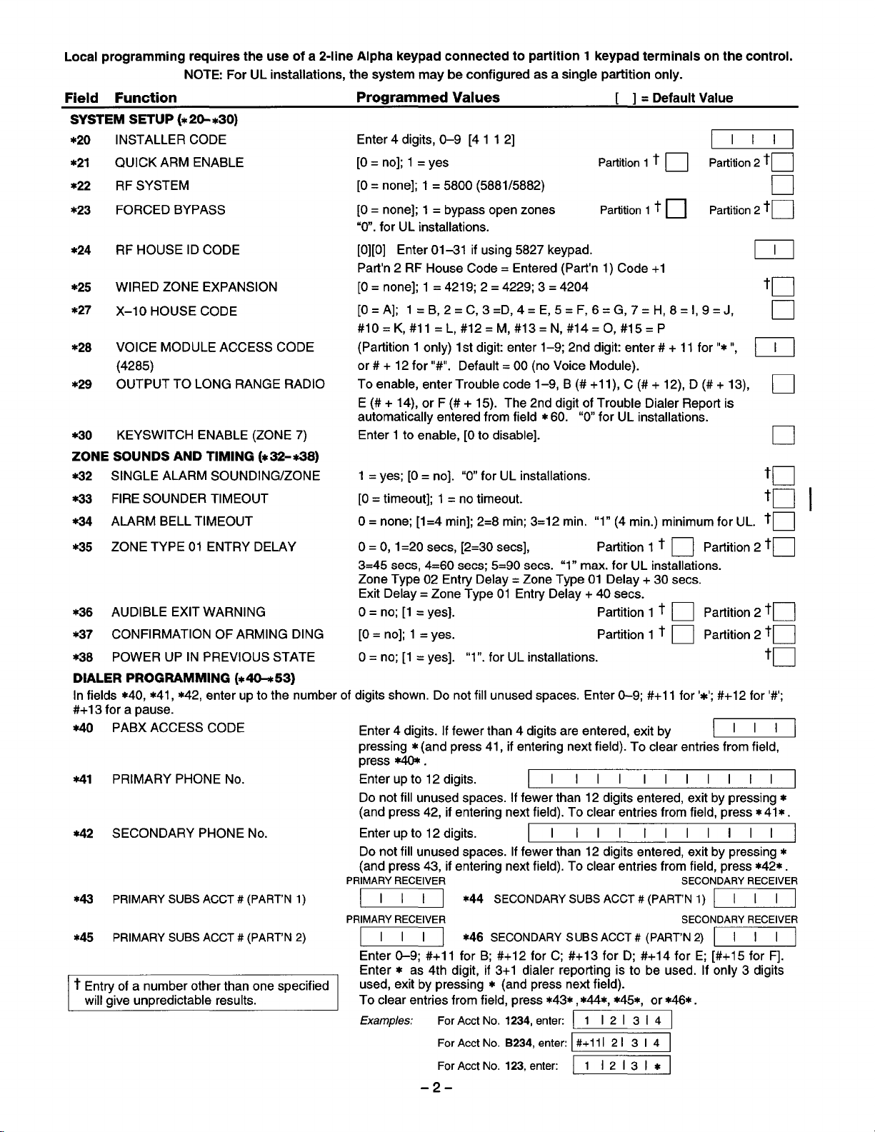
Local programming requires the use of a 2-line Alpha keypad connected to partition 1 keypad terminals on the control.
NOTE For UL installations, the system maybe configured as a single partition only.
Field Function
Programmed Values [ ] =
Default Value
SYSTEMSETUP (*2G*30)
*2(3
*21
*22
*23
*24
*25
*27
*28
*29
*3O
ZONE SOUNDS AND TIMING (*3% Y138)
*32
*33
*34 ALARM BELL TIMEOUT
INSTALLER CODE
QUICK ARM ENABLE
RF SYSTEM
FORCED BYPASS
RF HOUSE ID CODE
WIRED ZONE EXPANSION
X–10 HOUSE CODE
VOICE MODULE ACCESS CODE
(4285)
OUTPUT TO LONG RANGE RADIO
KEYSWITCH ENABLE (ZONE 7)
SINGLE ALARM SOUNDING/ZONE
FIRE SOUNDER TIMEOUT
Enter 4 digits, O-9 [4 11 2]
[0= no]; 1 = yes Partition
[0= none]; 1 = 5800 (5881/5882)
[0= none]; 1 = bypass open zones Partition
“O”. for UL installations.
[0][0] Enter 01-31 if using 5827 keypad.
Part’n 2 RF House Code= Entered (Part’n 1) Code +1
[0= none]; 1 = 4219; 2 = 4229; 3 = 4204
[O= A]; 1= B,2=C,3=D,4 =E,5=F,6=G,7 =H,8=I,9=J,
#10= K,#ll=L, #12= M,#13=N, #14=0, #15=P
(Partition 1 only) 1st digit enter 1-9; 2nd digit enter # + 11 for”*”,
or # + 12 for “#”. Default= 00 (no Voice Module).
To enable, enter Trouble code 1–9, B(#+11), C (#+ 12), D (#+ 13),
E (# + 14), or F (# + 15). The 2nd digit of Trouble Dialer Report is
automatically entered from field *60. “O for UL installations.
Enter 1 to enable, [0 to disable].
1 = yes; [0= no]. “O” for UL installations.
[0= timeout]; 1 = no timeout.
O= none; [1=4 rein]; 2=8 rein; 3=12 min.
“1” (4 min.) minimum for UL. to
1 t ❑ Partition 2 to
1 t ❑ Partition 2 to
IJJJ_l
u
to
m
to
to I
•1
•1
❑
❑
*35 ZONE TYPE 01 ENTRY DELAY
*36 AUDIBLE EXIT WARNING
*37 CONFIRMATION OF ARMING DING
POWER UP IN PREVIOUS STATE
*38
O= O, 1=20 sees, [2=30 sees], Partition 1 t
3=45 sees, 4=60 sees; 5=90 sees. “1” max. for UL installations.
Zone Type 02 Entry Delay= Zone Type 01 Delay +30 sees.
Exit Delay = Zone Type 01 Entry Delay + 40 sees.
O= no; [1 = yes]. Partition 1 t
[0= no]; 1 = yes. Partition 1 t
O= no; [1 = yes]. “1”. for UL installations.
❑ Partition 2 to
❑ Partition 2 to
❑ Partition 2 to
to
DIALERPROGRAMMING(40+53)
In fields *40, *41, *42, enter up to the number of digits shown. Do not fill unused spaces. Enter O-9; #+11 for ‘*’; #+12 for ‘#’;
#+13 for a pause.
*4O
PABX ACCESS CODE
PRIMARY PHONE
Ml
*42
SECONDARY PHONE
PRIMARY SUBS ACCT # (PART’N 1)
*43
PRIMARY SUBS ACCT # (PART’N 2)
*45
t Entry of a number other than one specified
will give unpredictable results.
No.
No.
Enter 4 digits. If fewer than 4 digits are entered, exit by
pressing *(and press 41, if entering next field). To clear entries from field,
press @@I.
Enter up to 12 digits.
Do not fill unused spaces. If fewer than 12 digits entered, exit by pressing *
(and press 42, if entering next field). To clear entries from field, press* 41 *.
Enter up to 12 digits.
Do not fill unused spaces. If fewer than 12 digits entered, exit by pressing *
(and press 43, if entering next field). To clear entries from field, press *42*.
PRIMARY RECEIVER
~]
PRIMARY RECEIVER
~] *46 SECONDARY SUBS ACCT # (PART’N 2) ~1
Enter O-9; #+1 1 for B; #+12 for C; #+13 for D; #+14 for E; [#+15 for F].
Enter * as 4th digit, if 3+1 dialer reporting is to be used. If only 3 digits
used, exit by pressing * (and press next field).
To clear entries from field, press *43*,*44*, *45*, or *6*.
Examples:
*44 SECONDARY SUBS ACCT# (PART’N 1) ~]
For Acct No. 1234, enter
For Acct No. B234, enter: #+11121314
For Acct No. 123, enter:
-2-
I Ill 1111111
I Ill
l1213i4
mzmzl
1111111
~
SECONDARY RECEIVER
SECONDARY RECEIVER
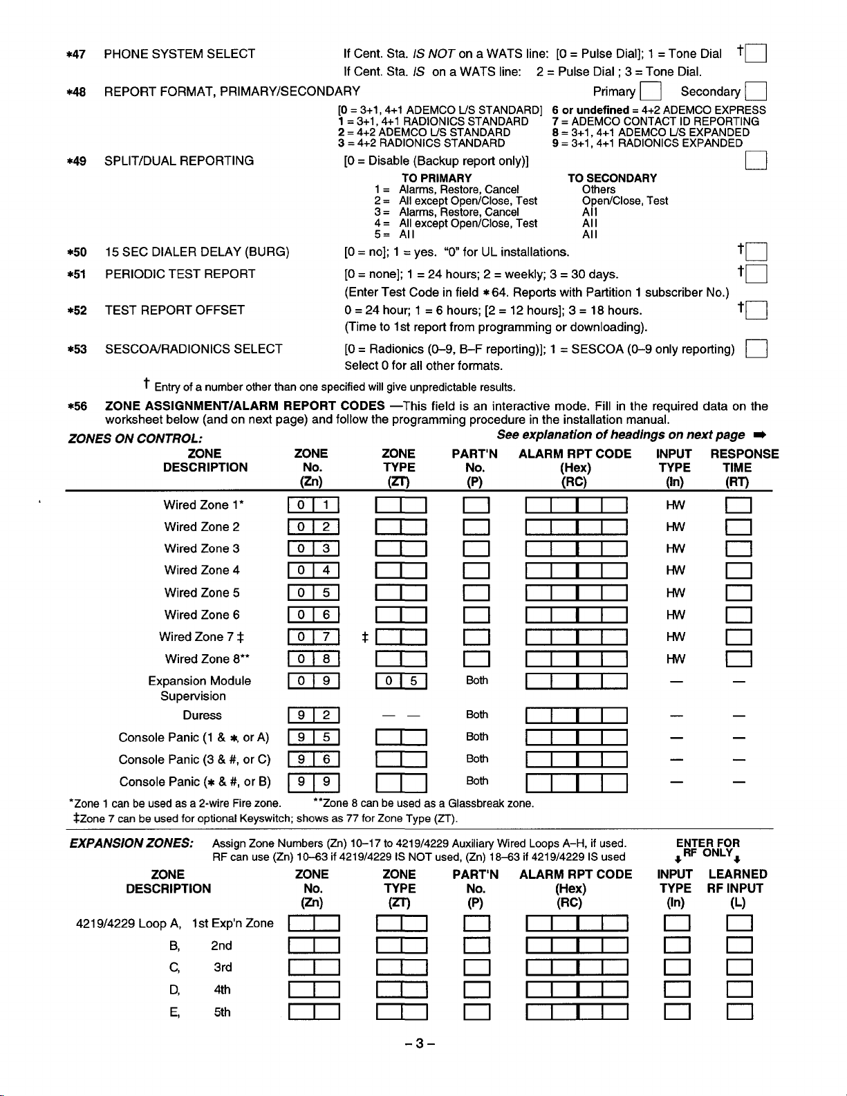
*47 PHONE SYSTEM SELECT
48 REPORT FORMAT, PRIMARY/SECONDARY
*49 SPLIT/DUAL REPORTING
*5O 15 SEC DIALER DELAY (BURG) [0= no]; 1 = yes.
PERIODIC TEST REPORT [0= none]; 1 =24 hours; 2 = weekly; 3 = 30 days.
*5I
*52 TEST REPORT OFFSET O=24 houv 1 = 6 hours; [2= 12 hours]; 3 = 18 hours.
*53 SESCOA/RADIONICS SELECT [0= Radionics (O-9, B-F reporting)]; 1 = SESCOA (O-9 only reporting)
of a number other than one specified will give unpredictable results.
t Entry
*56
ZONE ASSIGNMENT/ALARM REPORT CODES —This field is an interactive mode. Fill in the required data on the
worksheet below (and on next page) and follow the programming procedure in the installation manual.
ZONES ON CONTROL:
ZONE
DESCRIPTION TYPE
Wired Zone 1‘
Wired Zone 2
Wired Zone 3
Wired Zone 4
Wired Zone 5
Wired Zone 6
Wired Zone 7 t
Wired Zone 8“
Expansion Module
Supervision
Duress
Console Panic (1 & *, or A) ml
Console Panic (3& #, or C) ~~
Console Panic (*& #, or B) ml
●Zone 1 can be used
$Zone 7 can be used for optional Keyswitch; shows as 77 for Zone Type (iT).
as a 2-wire Fire zone.
ZONE
(Rj
m
m
m
m
m
m
m
m
m
m
lfCent. Sta. /S A/OTona WATS line: [O= Pulse Dial]; l =Tone Dial
If Cent. Sta. /S on a WATS line: 2 = Pulse Dial :3 = Tone Dial.
Primary U Secondary U
[0. 3+1, 4+1 ADEMCO L/S STANDARD] 6 or undefined = 4+2 ADEMCO EXPRESS
1 = 3+1, 4+1 RADIONICS STANDARD
2 = 4+2 ADEMCO IJS STANDARD
3 = 4+2 RADIONICS STANDARD 9 = 3+1, 4+1 RADIONICS EXPANDED
[0= Disable (Backup report only)]
TO PRIMARY
1= Alarms, Restore, Cancel
2 = All except Open/Close, Test
3 = Alarms, Restore, Cancel
4 = All except Open/Close, Test
5= All
“O for UL installations.
(Enter Test Code in field* 64. Reports with Partition 1 subscriber No.)
(Time to 1st report from programming or downloading).
Select Ofor all other formats.
See explanation of headings on next page m
ZONE
(m
PART’N ALARM RPT CODE INPUT RESPONSE
No. Fe) TYPE
(P)
7 = ADEMCO CONTACT ID REPORTING
8 = 3+1, 4+1 ADEMCO W EXPANDED
TO SECONDARY
Others
Open/Close, Test
Al I
Al I
Al I
*m
I
m
Both
Both
Both
Both
●*Zone 8 can be used as a Glassbreek zone.
I
—
(In) (RT)
Hw
Hw
I-fvv
Hw
Hw
Hvv
Hw
Hvv
—
.
—
—
—
to
tu
to
to
TIME
—
—
—
—
—
—
•1
.—
❑
EXPANS1ON ZONES:
ZONE
DESCRIPTION
421 9/4229 Loop A, 1st Exp’n Zone ~( 111
B, 2nd
c,
D,
E,
Assign Zone Numbers (Zn) 10-17 to 421 9/4229 Auxiliary Wired Loops A–H, if used.
RF can use (Zn) 10-63 if 4219/4229 IS NOT used, (Zn) 18-63 if 421 9/4229 IS used
ZONE
(%
mm
3rd
4th
5th
mm
mm
mm
ZONE
TYPE
(m
-3-
PART’N
No.
(P)
0
n
n
u
0
ALARM RPT CODE
WeC;)
I I
I
I
I I
I
I
I I
I
I
ENTER FOR
*RF ONLY*
INPUT
TYPE
(In)
I
n
n
n
I
n
[
n
LEARNED
RF INPUT
(L)
n
0

CONTINUED FROM PREVIOUS PAGE
ZONE
DESCRIPTION
ENTER FOR
~ RF ONLY4
ZONE
No. TYPE No. (Hex) TYPE RF INPUT
(Zn)
ZONE PART’N ALARM RPT CODE INPUT LEARNED
(m
(P)
(Rcj (In) (L)
4219/4229 Loop F,
G,
H, 6th
6th Exp’n Zone 111 ~] m
7th
mma
mma EEIJIzclcl
9th
10th
Ilth
12th
13th
14th
15th
16th
17th
18th
19th
20th
21st
22nd
mmn E1333nn
mmn rrrrlnrl
mmn rrrnnrl
mmn rEEnn El
mmn ErErlnn
mmn
mmn Errrlnn
mmn
mmn rrnnrln
mmn rrrnnn
mmn
mmn
mmn
mmn
~nn
U333nn
rE133nn
EIIl13nrl
Ern3rlrl
rrrrlrlrl
rrrrlnn
rrn3n El
EXPLANATION OF ZONE ASSIGNMENT TABLE HEADINGS
Zn = ZONE No.
ZT = ZONE TYPE
P = PARTITION No.
RC = ALARM REPORT CODE
In= LOOP INPUT TYPE
RT = RESPONSE TIME O= 10msec; 1 = 350 msec; 2 = 700 msec. Default Values for zones 01-08 = 1 (350 msec)
L = LEARNED RF INPUT Used with 5800 RF Loop Input Devices. Record transmitter input number.
Zone Nos. are from 01 to 63, 92, 95, 96, 99. Some are pre-assigned.
With Field *25 set for auxiliary wired loops (421 9, or 4229), use Zone Nos. 10-17 for loops A-H.
With Field *22 set for RF (5800), use Zone Nos. 18-63 if 4219/4229 is ALSO used, or 10-63 if 4219/4229 is NOT used.
00= Not Used
01 = Entry/Exit #1
02= Entry/Exit #2 07= 24 Hr Audible 22= Disarm
03= Perimeter
04= Interior Follower 09= Fire 24= Silent Burglary
lor2 Default Values for zones 01 -08= [1].
Two Hex Digits.
For contact ID reporting, this is enabling code only. Enter any hex digit (other than 00) in the first pair of
boxes. The second pair of boxes is ignored.
HW Hard Wire
AW Aux Wire (4219 or 4229)
05= Trouble Day/Alarm Night 20. ArrrWtay
06 =24 Hr Silent
08 =24 Hr Aux
10 = Interior w/Delav
.-
For each Hex Di it, entec
14 forE, 15 forl? If “OO’’isenteredastheflrstdigit,t herewill benoreportforthatzone.
—,
21 = Arm-Away
23= No Alarm Response
00-09 for O-9, 10 for A, 11 for B,12 for C, 13 for D,
E_nter3 for RF: Supervised RF
Enter 4 for UR: Unsupervised RF
Enter 5 for BR: Button Type RF
I 1
~
-4-

TO PROGRAM SYSTEM STATUS, & RESTORE
REPORTCODES
With a 3+1 or 4+1 Standard Format:
box: 1-9, 0, B, C, D, E, or F. Enter “#+10” for O, ‘#+11” for B,
‘#+1 2“ for C, “#+1 3“ for D, “#+14“ for E, “#+15“ for F.
A “O”(not “#+1O“)in the
A “O”(not “#+1O“)in the second box will result in automatic
advance to the next field when programming.
With an Expanded or 4+2 Format: Enter codes in both hexes
(1st and 2nd digits) for 1-9,0, or B-F, as de scribed above.
A “O”(not “#+1 O“) in the second box will eliminate the ex-
panded message for that repofl.
A ‘O” ( not “#+1 O“)in both boxes will disable the report.
With Ademco Contact ID Reporting: Enter any digit (other
than “O”)in the
second boxes will be ignored).
A “O”( not “#+1O“)in the firstbox will disable the report.
Examples:
For Code 3 (single digit), entec
For Code 32 (two digits), entec
For Code B2 (Hexadecimal), enter: -l
EXIT ERROR REPORT CODE
*59
TROUBLE REPORT CODE
*6O
BYPASS REPORT CODE
*61
AC LOSS REPORT CODE
*62
LOW BAT REPORT CODE
*63
TEST REPORT CODE
*64
OPEN REPORT CODE
*65
(*59+76, & *89):
Enter a code in the first
first box will disable a report.
first box, to enable zone to report (entries in the
m
m
ml
ccl
El
*75 RF XMTR LO BAT RST RPT CODE
*76 TEST RESTORE RPT CODE
OUTPUT AND SYSTEM SETUP (*8G*93)
*82
CUSTOM ALPHA EDITING: (Also entered from field
*56): See
ADD/DELETE RF INPUT IDs
*83
*56): See procedure
EVENT LOG 80% FULL RPT CODE
*89
EVENT LOGGING
O= None; 1 = Alarm/Alarm Restore; 2 = Trouble/Trouble
Restore; 4 = Bypass/Bypass Restore; 8 = Open/Close.
Exarnp/e: To select “Alarm/Alarm Restore”, and
“Open/Close”, enter 9 (1 + 8); To select all, enter#15.
Default = “3.
Note: System messages are logged when any non-zero
selection is made.
*91
OPTION SELECTION
“O for UL installations.
PHONE LINE MONITOR ENABLE
*92
[0= Not used]
1 = Keypad display
2 = Keypad display plus keypad trouble sound
3 = Same as “2, plus Device #2 STARTS. If either partition
Note Device #2 must either be programmed to be
STOPPED in field *8O or STOPPED by Code+ # + 8 + 2.
procedure in instructions.
in instructions.
when line is faulted
is armed, external sounder activates also.
(Also entered from field
[0= None]; 4= AAV ❑
III
m
u
•1
❑
ARM AWA’f/STAY RPT CODE
*66
t 2nd digit is automatically sent as the 2nd digit of the
zone alarm report code programmed in *56, if
expanded or 4+2 reporting is selected.
tt 2nd digit is automatically sent as the user number if
expanded or 4+2 reporting is selected.
RF XMTR LOW BAT REPORT CODE
*67
CANCEL REPORT CODE
*68
Part.111 11~
RESTORE REPORT CODES (*70-*76)
*7O
ALARM RESTORE RPT CODE
2nd digit is automatically sent as the 2nd digit of the —
zone alarm report code programmed in *56, if
expanded or 4+2 reporting is selected.
TROUBLE RESTORE RPT CODE
*71
BYPASS RESTORE RPT CODE
*72
AC RESTORE RPT CODE
*73
LOW BAT RESTORE RPT CODE
*74
Y T]
Yll]
III
CIl
I_.I.-l
L-!-
—
II
NUMBER OF REPORTS IN ARMED PERIOD m
e3
[0= 10 Alarm/Alarm Restore Reports]; 1 = Unlimited. —
“l” for UL installations.
DOWNLOAD INFORMATION (*94, *95)
DOWNLOAD PHONE
*94
I Ill 1111111
Enter up to 12 digits, O-9; #+11 for ‘x’; #+12 for %’;#+13 for a
pause. Do not fill unused spaces. If fewer than 12 digits
entered, exit field by pressing * (and press 95, if entering next
field). To clear entries from field, press *94*.
Note: In UL installations, down loading may only be
performed if a technician is at the site.
RING DET COUNT FOR DOWNLOADING
*95
[0= Disable Station Initiated Download]; 1-14 = numbe~
rmgs(l-9, #+10 =10, #+11 =11, #+12 =12, #+13=13,
# +14 =14); 15= answering machine defeat (# +15 =15)
Note Do not enter ‘O if using 4285 Voice Module.
*86 INITIALIZES DOWNLOAD ID, SUBSCRIBER
ACCOUNT No.
No data entry required.
*97 SETS ALL PROGRAM FIELDS TO DEFAULT
VALUES:
No data entry required.
*98 and *99 USED TO EXIT PROGRAM MODE
(see page “7)
No.
FOR INITIAL DOWNLOAD:
n
Y Reports with Partition 1 Subscriber No.
-5-

OUTPUT RELAYS/POWERLINE CARRIER DEVICES WORKSHEET FOR *80, and *81.
Applicable only if Relays andlor Powerline Carrier Devicess are to be used.
*6O OUTPUT DEVICES -
the programming procedure in the installation manual as you enter the data during the displays and prompts that appear
in sequence.
/Votes: 1. For Relays,
2. For Powerline Carrier devices, field *27 must be programmed with a House Code.
3. Tampers of contacts or expansion units cannot be used to operate devices.
This is an interactive menu mode. Fill in the required data on the worksheet on below and follow
field *25 must be programmed for a 4229 (Relays 01 and 02), OR for a 4204 (Relays 01 to 04).
I
I @either or both*
DEVICE
NUMBER
OUTPUT REIAY
OR P. L.C. D.* 01
OUTPUT RELAY
OR P.L.C.DT 02
OUTPUT
OR P.L.C.D.* 03
OUTPUT RELAY
OR P.L.C.D7 04
P.L.C.D.* 05
P.LC.DT 06
P.LC.D7 07
P.L.C.D.* 08
Where
X-10 SELECT = Powerline Carrier Device Enter
RELAY
~‘ p. L.C.D. = Powerline Carrier Device (X-1 O).
A = DEVICE ACTION O = No Response;1 = Closefor2 see;2 = Closeand stayclosed;3 = Pulseon and off.
EV = EVENT O = Not used; 1 = Alarm; 2 = Fault; 3 = Trouble.
ZL =
ZT = ZONE TYPE/SYSTEM OPERATION
P = PARTITION No. 1,2, or Ofor Any
x-lo
SELECT
❑ ❑ ❑ n ❑0 ❑
❑ ❑ ❑
❑ ❑ ❑
❑ ❑ ❑
❑ llmnnlmln
ZONE LIST 1, 2, or 3 (from Field *81) or O= Not Used.
Choices for Zone Types are:
00=
01 = Entry/Exit#l
02= Entiy/Exit#2
03= Perimeter
04= Interior Follower
05= Trouble Day/Alarm Night
Choices for System Operation are:
20=
21 = Arming-Away 39= Any Fire Alarm
22= Disarming (Code + OFF)
31 = End of Exit Time
32= Start of Entry Time
33= Any Burglary Alarm
36= *’At Bell Timeout*’*
*’ Use O
*** Or at Disarming, whichever occurs earlier.
ACTION EVENT LIST SYST OP’N
(A) (EV) (ZL) (n) (P)
“START” ZONE LIST: Upon alarm, fault, or trouble of ANY zone on this list, device action will START.
‘STOP RESTORE of ZONE LIST: Upon restore of ALL zones on this list, device action will STOP. It
Not Used 06= 24 Hr Silent
Armin@tay
(Any)forPartition No. (P) entry.
START
ZONE
ZONE TYPE PART’N
No.
RESTORE of ZONE TYPE PART’N
ZONE LIST ISYST OP’N
STOP
● either or both ●
(ZL) (ZT)
❑ ❑0 ❑
n ❑n ❑
n ❑n ❑
0 ❑0 ❑
❑ ❑
❑ ❑
❑
❑
❑
“1”if Powerline Carrier Device is being used, enter “O if relay is being used.
need not be same list as used for START.
07= 24 Hr Audible
08= 24 Hr Aux
09= Fire Trouble
10= Interior w/Delay
24= Silent Burglary
38= Chime
40= Bypassing
41 = **AC Power Failure
42=
●*System Battety Low
43= Communication Failure
Note: Any zone in “Z7 oin,7 g into akrrm
fault, or trouble WI I actuate relay. ‘
An zone of that type that restores
{WII stoo relav action.
52= KiSSOff
58= Duress
In normal operation mode:
Note:
Code + # + 7 + N Key Entry starts Device N.
Code + # + 8 + N Key Entry stops Device N.
n ❑
n ❑
III ❑
loo ❑
Inn ❑
R
-6-

*81
ZONE LISTS FOR OUTPUT DEVICES – This is an interactive mode. Fill in the required data on the worksheet
below and follow the procedure in the installation manual as you enter the data during the displays and prompts that
appear in sequence.
Note: Record desired zone numbers below. More or fewer boxes than shown maybe needed, since any list may
include any or all of system’s zone numbers.
Zone List 1: Started or stopped by zone numbers (enter 00 to end entries).
❑0 ❑ 0, ❑0 ❑0, ❑ 0, ❑ n ❑0 ❑ 0 ❑ 0 ❑netc
Zone List 2: Started or stopped by zone numbers (enter 00 to end entries).
❑0, ❑ n ❑n ❑n ❑ n, ❑ 0 ❑n ❑ 0, ❑ 0 ❑mtc
Zone List
3: Started or stopped by zone numbers (enter 00 to end entries).
❑ 0, ❑ 0 ❑ 0 ❑0, ❑ 0 ❑0 ❑0 ❑ 0 ❑ n, IIlnetc
SPECIAL MESSAGES
OC =
OPEN CIRCUIT (no communication between Console and Control).
EE or ENTRY ERROR= ERROR (invalid field number entered; re-enter valid field number).
After powering up, AC, dl (disabled) or System Busy and NOT READY will be displayed after approximately 4 seconds. This
will revert to READY in appx. 1 minute, which allows PIRS, etc. to stabilize. To bypass this delay, press: [#] + [0].
If E4 or E8 appears, more zones than the expansion units can handle have been programmed. Correct the programming and
then completely de-power and re-power the control to clear this indication and remove the disable indication.
TO ENTER PROGRAMMING MODE:
POWER UP, then depress [*] and [#] both at once, within 50 seconds of powering
1.
OR
Initially, key Installer Code (4+ 1 + 1 +2) plus 8 + O + O.
2.
OR
If different Installer Code is Droarammed. kev: New I nstaller Code + 8 + O + O.
3.
(if *98 was used to exit previous~, method 1 ~bove must be used to enter the program mode again)
TO EXIT PROGRAMMING MODE:
*98 Exits programming mode and prevents re-entry by Installer Code + 8+ O+ O. If *98 is used to exit programming
mode, system must be powered down, and method 1 above used to enter the programming mode.
*98 Exits programming mode and a//ows re-entry by Installer Code + 8 + O + O or: Power-up, then press “*” and “#”
within 50 seconds of power up.
up.
-7-

(ADEIvICOJ
ALARM DEVICE MANUFACTURING CO.
165 Eileen Way, Syosaet, New York 11791
A DIVISION OF PITIWAY CORPORATION
Copyright @ 1995 PITTWAY CORPORATION
 Loading...