


9,,
9
6
6
7
7
$
$
6
6
(
(
6HFXULW\6\VWHP
,QVWDOODWLRQDQG6HWXS*XLGH
*
AWAY
NO AC
STAY
CHIME
INSTANT
BAT
ALARM
BYPASS
CHECK
FIRE
NOT READY
OFF AWAY STAY
2
1
MAX TEST BYPASS
INSTANT CODE CHIME
897
READY
0
*
PANIC
ARMED
READY
3
654
#
•
•
•
•
•
•
•
•
•
•
•
•
•
•
•
•
•
•
•
®
N7227V5 10/00

RECOMMENDATIONS FOR PROPER PROTECTION
DINING
KITCHEN
BEDROOM
BEDROOM
BEDROOM
BEDROOM
LIVING ROOM
✪
✪
✪
✪
✪
▲
▲
BEDROOM
BDRM
BDRM
DINING
LIVING ROOM
TV ROOM
KITCHEN
■
■
■
✪
✪
✪
✪✪
✪
▲
✪
✪
✪
BEDROOM
BEDROOM
TO
BR
■
■
■
■
■
LVNG RM
BASEMENT
KTCHN
▲
▲
.
CLOSED
DOOR
GARAGE
▲
Smoke Detectors for Minimum Protection
Smoke Detectors for Additional Protection
Heat-Activated Detectors
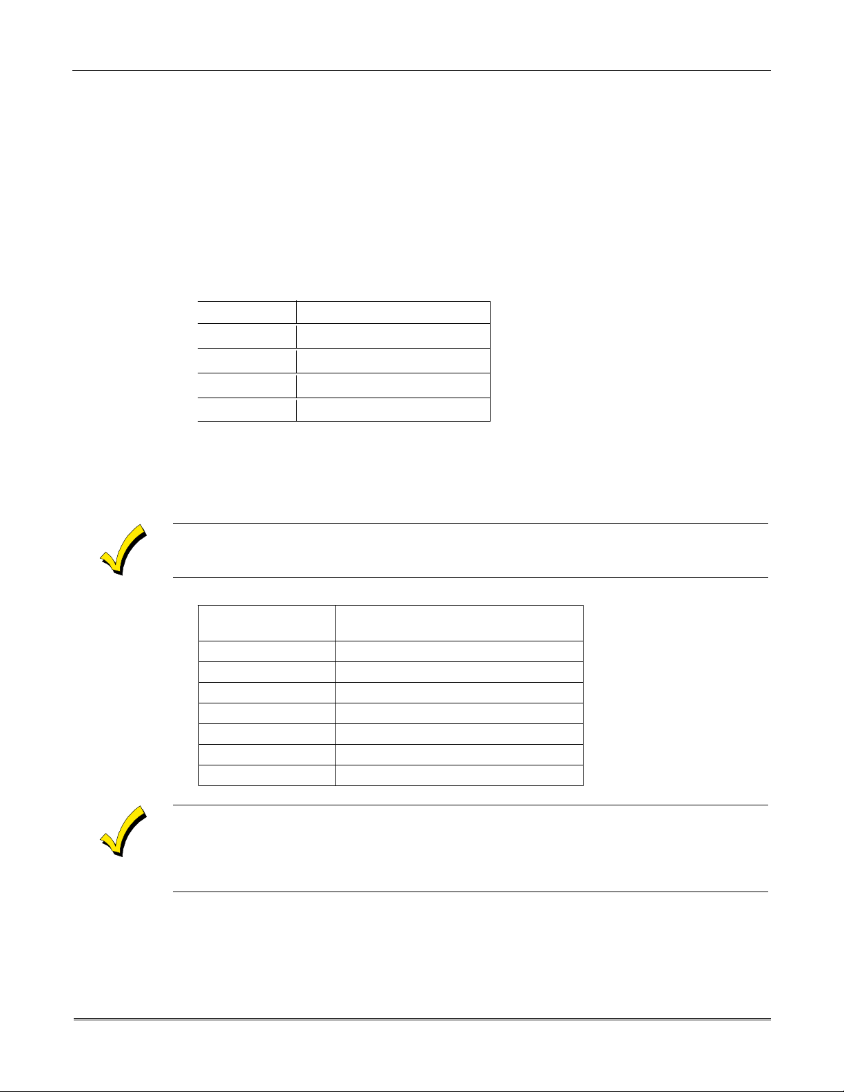
The following recommendations for the location of fire and burglary detection devices help provide
proper coverage for the protected premises.
Recommendations for Smoke and Heat Detectors
With regard to the number and placement of smoke/heat detectors, we subscribe to the
recommendations contained in the National Fire Protection Association's (NFPA) Standard #72
noted below.
Early-warning fire dete ctio n is be st achie ve d by th e in stallatio n o f f ire de te ction equ ipm en t in all
rooms and areas of the household as follows: For minimum protection, a smoke detector should
be installed outside of each separate sleeping area, and on each additional floor of a multi-floor
family living unit, includin g basements. The installation of sm oke detectors in kitc hens, attics
(finished or unfinished), or in garages is not normally recommended.
For maximum protection, the NFPA recommends that you install heat or smoke detector s in
the living room, dining room, bedroom(s), kitchen, hallway(s), attic, furnace room, utility and
storage rooms, basements and attached garages.
In addition, we recommend the following:
• Install a smoke detector inside every bedroom where a smoker sleeps.
• Install a smoke detector inside every bedroom where someone sleeps with the door partly or
completely closed. Smoke could be blocked by the closed door. Also, an alarm in the hallway
outside may not wake up the sleeper if the door is closed.
• Install a smoke detector inside bedrooms where electrical appliances (such as portable
heaters, air conditioners, or humidifiers) are used.
• Install a smoke detector at bo th ends of a hallway if the hallway is more than 40 feet (12
meters) long.
• Install smoke detectors in any room where an alarm control is located, or in any room where
alarm control connections to an AC source or phone lines are made. If detectors are not so
located, a fire within the room could prevent the control from reporting a fire or an
intrusion.
THIS CONTROL COMPLIES WITH NFPA REQUIREMENTS FOR
TEMPORAL PULSE SOUNDING FOR FIRE NOTIFICATION APPLIANCES.
Recommendations for Proper Intrusion Protection
For proper intrusion coverage, sensors should be located at every possible point of entry to a home or
commercial premises. This would include any skylights that may be present, and the upper windows
in a multi-level building.
In addition, we recommend th at radio backup be u sed in a security system so that alarm sig nals can
still be sent to the alarm monitorin g station in the event that the teleph one lines are out of order
(alarm signals are normally sent over the phone lines, if connected to an alarm monitoring station).
ii

Table of Contents
••••••••••••••••••••••••••••••••••••••••••••••••••
SECTION 1. Introduction............................................................................................................................1–1
Description........................................................................................................................................................1-1
Features.............................................................................................................................................................1-1
SECTION 2. Installing the Control...........................................................................................................2–1
Mounting the Cabinet ......................................................................................................................................2-1
Installing the Lock (if used) .............................................................................................................................2-1
Mounting the Control's Circuit Board Alone in the Cabinet.........................................................................2-2
Mounting the Control and RF Receiver Circuit Boards Together.................................................................2-2
Standard Phone Line Connections ..................................................................................................................2-3
SECTION 3. Installing Remote Keypads .................................................................................................3–1
Keypads That May Be Used.............................................................................................................................3-1
Wiring to the Keypads......................................................................................................................................3-1
Mounting the Keypads .....................................................................................................................................3-2
Supplementary Power for Additional Keypads ..............................................................................................3-2
Preliminary Checkout Procedure ....................................................................................................................3-3
SECTION 4. Basic Hardwired Zones 1–6 .................................................................................................4–1
Installing the Hardwired Zones.......................................................................................................................4-1
Programming Hardwired Zones ......................................................................................................................4-2
SECTION 5. Wireless Expansion (5800 System) ....................................................................................5–1
About Wireless Expansion ...............................................................................................................................5-1
Installing the 5881/5882 Receiver ...................................................................................................................5-2
Installing the 5800TM Module ........................................................................................................................5-3
About Jam Detection and Reporting ...............................................................................................................5-3
5800 Series Transmitters.................................................................................................................................5-3
Installing 5800 Series Transmitters................................................................................................................5-6
SECTION 6. Relay Output Devices...........................................................................................................6–1
Relay Device Basics..........................................................................................................................................6-1
4204 Relay Modules..........................................................................................................................................6-1
Programming Options ......................................................................................................................................6-2
SECTION 7. 4285 and 4286 VIP Module...................................................................................................7–1
Installing the (Voice Interactive Phone) Module............................................................................................7-1
Programming the Control for Phone Access...................................................................................................7-4
Checking the Operation of the VIP Module....................................................................................................7-4
SECTION 8. External Sounders.................................................................................................................8–1
Compatible Sounders.......................................................................................................................................8–1
Sounder Connections and Power ....................................................................................................................8–2
SECTION 9. Long-Range Radio.................................................................................................................9–1
About Long-Range Radio..................................................................................................................................9-1
Programming for Long-Range Radio...............................................................................................................9-1
Dynamic Signaling Feature .............................................................................................................................9-2
SECTION 10. Audio Alarm Verification (AAV) Unit.............................................................................10–1
About Audio Alarm Verification ....................................................................................................................10-1
iii

SECTION 11. Final Power-Up ....................................................................................................................11–1
Earth Ground Connections ............................................................................................................................11-1
Wiring the AC Transformer...........................................................................................................................11-1
AC Power-Up ..................................................................................................................................................11-2
Calculating the Battery Size Needed ............................................................................................................11-2
Connecting the Backup Battery.....................................................................................................................11-3
SECTION 12. Mechanics of Programming..............................................................................................12–1
About Programming .......................................................................................................................................12-1
Entering the Program Mode ..........................................................................................................................12-1
SECTION 13. Zone Response Type Definitions .....................................................................................13–1
Zone Type Definitions.....................................................................................................................................13-1
SECTION 14. Data Field Descriptions ......................................................................................................14-1
Descriptions of System Data Fields...............................................................................................................14-1
SECTION 15. Zone Programming..............................................................................................................15–1
About Zone Programming .............................................................................................................................15–1
SECTION 16. Output Device Programming............................................................................................16–1
Programming Options Defined .....................................................................................................................16–1
Programming Output Relays........................................................................................................................16–3
SECTION 17. Zone Lists .............................................................................................................................17–1
SECTION 18. Alpha Descriptor Programming ......................................................................................18–1
About Alpha Descriptor Programming..........................................................................................................18-1
Zone Descriptors.............................................................................................................................................18-1
SECTION 19. Remote Programming and Control (Downloading)....................................................1 9–1
SECTION 20. System Communication .....................................................................................................20–1
Panel Communication with Central Station.................................................................................................20-1
Report Code Formats......................................................................................................................................20-1
Table of Contact ID Event Codes...................................................................................................................20-2
SECTION 21. System Operation ................................................................................................................21–1
Security Codes ................................................................................................................................................21-1
Keypad Functions...........................................................................................................................................21-2
Trouble Conditions .........................................................................................................................................21-4
SECTION 22. Testing the System ...............................................................................................................22-1
Test Procedure ................................................................................................................................................22-1
SECTION 23. Specifications & Accessories ............................................................................................23–1
Specifications ..................................................................................................................................................23-1
Accessories (Compatible Devices)..................................................................................................................23-2
APPENDIX A REGULATORY AGENCY STATEMENTS .........................................................................A-1
APPENDIX B Limitations and Warranties................................................................................................B-1
Programming Form .....................................................................................................................................Insert
iv

SECTION 1
Introduction
••••••••••••••••••••••••••••••••••••••••••••••••••
In This Section
Description
♦
••••••••••••••••••••••••••••••••••••••••••••••••••
Features
♦
Description
The VISTA–10SE is a control that supports up to 22 hardwired and wireless zones, plus
remote keypads.
Features
Basic Hardwired Zones
Provides 6 basic hardwired zones having the following characteristics:
•
Zones 1-6 response time is 300–500 milliseconds.
•
Zone 3 programmable fast response time is 10–15 milliseconds.
•
EOLR supervision supporting N.O. or N.C. sensors
•
Zone 5 supports as many 4-wire smoke or heat detectors as can be powered from the
control).
•
Zones 7, 95, and 96 are keypad Panics.
•
Zone 8 is Duress.
•
Zone 9 is Tamper.
Optional Expansion Zones
Wireless Expansion:
•
Supports up to 16 wireless zones.
•
Requires the use of a 5881 (5882 in Canada) type RF receiver (with 5800 Series wireless
transmitters), as shown below.
Receiver Model No. of Zones
5881L (5882L*) Up to 8 5800
5881M (5881M*) Up to 16 5800
5881H (5882H*) Up to 16 5800
*
Used in Canada.
Remote Keypads
Up to 4 of any of the following keypads may be used:
Fixed-Word Keypads:
*
This keypad cannot be used if a 4285/4286 VIP Module is being used.
6127*, 6128, and 6137.
Transmitter Type
Alpha Keypads
When programming from a keypad, a 6139 2-line alpha keypad must be connec ted (but need
not stay in the system).
6139 (2-line alphanumeric display).
6138 (1-line alphanumeric display).
1–1

VISTA-10SE Installation and Setup Guide
Security Codes
• One Master code for entire system (User 2). Installer code is User 1.
• 4 secondary user codes (Users 3–6).
• One duress code (User 8).
Duress Code:
An emergency code that, when used to disarm or arm the system, will send a
silent duress message to the central station
Keypad Panic Keys
•
Up to 3 programmable panic key functions are provided.
•
Designated as Zones 7, 95, 96.
•
Activated by wired and wireless keypads.
•
Reported separately.
Paging Feature
If the paging feature has been programmed for your system, your pager will respond to
certain conditions as they occur in your system, and display code numbers indicating the type
of condition that has occurred.
Quick Arm Feature
“Quick Arm” may be programmed, allowing use of the [#] key in place of the security code for
arming (Quick Arm will not work unless the Master code has been programmed into the
system).
Optional Bell Supervision
This is a hardware-enabled option, achieved by cutting a red jumper on the PC board. If the
“Alarm Output” loop connected to an external sounder is then opened or shorted, a “bell
trouble” message will be displayed at the touchpads, accompanied by a trouble sound. A
trouble report will also be sent to the central station.
.
1-2
Optional RF Jam Detection for 5800 Wireless Systems
If RF jam detection is programmed for a 5800 RF system, the RF receiver will detect a
condition that may impede proper RF reception (i.e., jamming or other RF interference). Such
a condition will produce a message display, and a report will be sent to the central
monitoring station (if trouble reporting is enabled).
Optional Output Relays
•
Up to 4 relays using one 4204 Relay Module.
•
Actions programmable to respond to zone activity or manual keypad ent ries.
Optional VIP Module
•
Supports the ADEMCO 4285/4286 VIP Module.
•
Provides access to t he system via on-premises or off-premises phones for arming,
disarming, etc., plus control of relay outputs.
Optional Long-Range Radio
Allows all messages that have been programmed to go to the primary telephone number to be
reported additionally to a 7720 PLUS or 7820 radio.

Alarm Output
•
Provides a 12VDC, 2 AMP output that can drive the compatible sounders listed in the
EXTERNAL SOUNDERS section (assumes a fully charged battery is connected).
•
Steady output for burglary/panic, or temporal pulse sounding output for fire notification,
as required by UL.
•
Uses current-limiting circuitry for protection.
Auxiliary Power Output
•
Provides 12VDC, 500mA maximum. Uses current limiting circuitry for protection.
•
This output interrupts for smoke detector reset if 4-wire smoke detectors are used.
Programming
•
Programmed options are stored in electrically erasable, nonvolatile EEPROM memory
(information can be reprogrammed at any time and will not be lost in the event of a power
loss).
•
The system can be uploaded, downloaded, or controlled via an IBM-compatible computer,
using ADEMCO's Compass Windows downloading software, and a modem specified by
ADEMCO.
Keypad programming consists of:
•
Data field programming.
•
Interactive (menu) mode programming.
Section 1 - Introduction
For programming from a keypad, a 6139 2-line alpha key pad must be c onnected (but need not
stay in the system).
Communication Formats Supported
•
ADEMCO Low Speed (Standard or Expanded)
•
Sescoa/Radionics (Standard or Expanded)
•
ADEMCO Express
•
ADEMCO Contact ID
Zone Descriptors
You can assign alpha descriptors to all zones (useful only when using alpha keypads and/or
the 4285/4286 VIP Module).
AC Power Supply
Uses No. 1321, 120VAC plug-in transformer with 16.5VAC 25VA output (1321CN in
Canada).
Backup Battery
Rechargeable (Sealed Lead Acid) 12VDC, 4AH minimum.
1-3

VISTA-10SE Installation and Setup Guide
1-4
SECTION 2
Installing the Control
••••••••••••••••••••••••••••••••••••••••••••••••••
In This Section
Mounting the Control and RF Receiver Circuit
Mounting the Cabinet
♦
Installing the Lock
♦
Mounting the Control's Circuit Board Alone in
♦
the Cabinet
••••••••••••••••••••••••••••••••••••••••••••••••••
Mounting the Cabinet
Mount the control cabinet to a sturdy wall using fasteners or anchors (not supplied), in a
clean, dry area that is not readily accessible to the general public. Four mounting holes are
provided at the back of the cabinet for this purpose.
If an RF receiver is being used and you intend to mount its PC board within the cabinet, note
the following:
•
Do not mount the cabinet on or near metal objects. This will decrease RF range and/or
block RF transmissions from wireless transmitters.
♦
Board in the Cabinet
Standard Phone Line Connections
♦
•
Do not locate the cabinet in an area of high RF interference (revealed by frequent or pro-
longed lighting of the LED in the receiver after it is operational). Random flicker is OK.
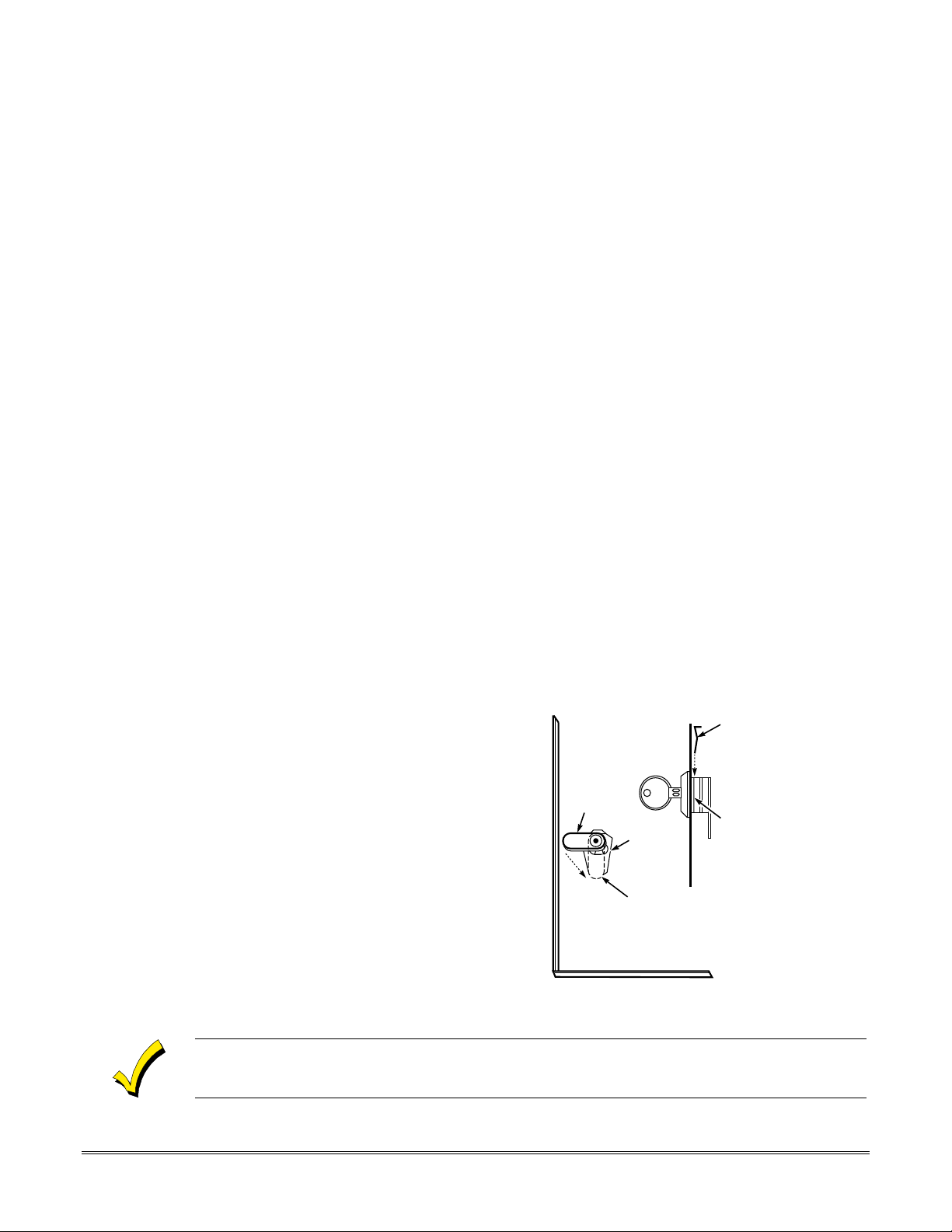
Installing the Lock
Use an ADEMCO No. N6277 Cam Lock and No. N6277–1 Push-On Clip (Retainer Clip).
NOTE:The cabinet can be closed and secured
1. Remove the cabinet door.
removable for servicing and is easily
re-installed.
2. Remove the lock knockout from the
control cabinet door. Insert the key
into the lock. Position the loc k in the
hole, making certain that the latch
will make contact with the latch
bracket when the door is closed.
3. Hold the lo ck steady, and insert the
retainer clip into the retainer slots.
Position the clip as illustrated in
order to permit easy removal.
edge.
It is easily
without
a lock by using 2 screws in the cover's
LOCKED
RETAINER
CLIP
UNLOCKED
CABINET DOOR BOTTOM
Figure 1. Installing the Lock
RETAINER CLIP
(NOTE POSITION)
RETAINER
SLOTS
V10SE-002-V0
Before installing the cabinet's contents, remove the metal c abinet knockouts required for wiring
entry. Do not attempt to remove the knockouts after the circuit board has been installed.
2–1
VISTA-10SE Installation and Setup Guide
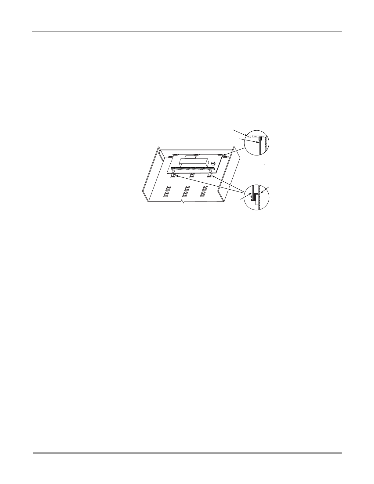
Mounting the Control's Circuit Board Alone in the Cabinet
To mount the circuit board alone in the cabinet, follow these steps:
1. Hang two mounting clips* (provided ) on the raised cabinet tabs (see Detail B in Figure 2
below).
2. Insert the top of the circuit board between the rows of slots at the top of the cabinet as
shown in Detail A.
3. Position the base of the board onto the mounting clips and secure both to the cabinet with
the supplied screws (see Detail B).
*
These mounting clips are also used for mounting the same end of the circuit board when an RF
receiver is mounted above it, as in Figure 3.
CABINET
CIRCUIT BOARD
+
+
CIRCUIT
BOARD
DETAIL A
SIDE VIEW
OF BOARD
SUPPORTING
SLOTS
CABINET
DETAIL B
SIDE VIEW
OF MOUNTING
CLIPS
Figure 2. Mounting the Control's Circuit Board Alone in the Cabinet
Mounting the Control and RF Receiver Circuit Board in the Cabinet
To mount the control and RF receiver boards together in the cabinet, do the following:
1. Hang two mountin g clips (p rovid ed with receiv er) o n the raise d cabine t tabs, as shown in
Detail B in Figure 3.
2. Insert the top of the receiver board (removed from its own case as described in its
instructions) between the rows of slots at the top of the cabinet, as shown i n Detail A.
3. Position the base of the receiver board onto the mounting clips and secure both to the
cabinet with the supplied screws (see Detail B).
4. Hang two mounting clips (supplied with the contro l board), on the raise d cabinet tabs as
shown in Detail C in Figure 3.
5. Insert the top of the control board into the slots of the mounting clips secured in step 3
above.
6. Position the lower end of the control board into place on the mounting clips and secure
both to the cabinet with the two supplied screws.
7. Insert both grounding lugs (supplied with the receiver) through the top of the cabinet
into the left-hand terminals of the antenna blocks (located at the upper edge of the
receiver board), and secure them to the cabinet with the screws provided, as shown in
Detail D.
8. Insert the receiv er's antennas thr ough the top of the cabinet, into the bloc ks' right-hand
terminals, and tighten the screws.
Refer to setup and wiring instructions for the receiver in the WIRELESS EXPANSION (5800
RF SYSTEMS) section.
V10SE-003-V0
2-2
Section 2 - Installing the Control
BOARD
SUPPORTING
SLOTS
MOUNTING
CLIP
MOUNTING
CLIP
CABINET
HOLES FOR ANTENNAS
AND GROUNDING LUGS
RECEIVER CIRCUIT BOARD
(See Detail D)
++
CONTROL
CIRCUIT
BOARD
SCREW
(2)
GROUNDING
LUG
(2)
RCVR BRD
++
ANTENNA AND GROUNDING LUG INSTALLATION
DETAIL D
ANTENNA
(2)
CIRCUIT BOARD
ANTENNA
MOUNT
(2 PLACES)
CABINET
DETAIL A
SIDE VIEW
OF BOARD
SUPPORTING SLOTS
DETAIL B
SIDE VIEW
OF MOUNTING
CLIP
DETAIL C
SIDE VIEW
OF MOUNTING
CLIP
V10SE-004-V0
Figure 3. Mounting the PC Board and RF Receiver Together in the Cabinet
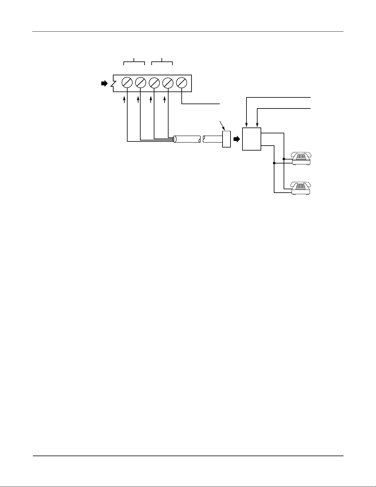
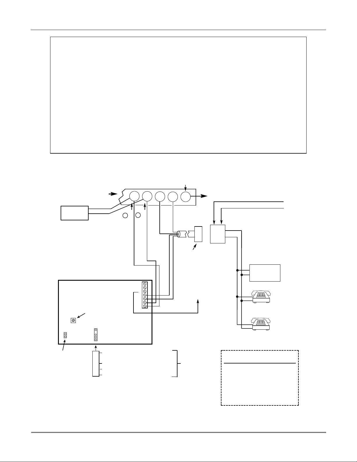
Standard Phone Line Connections
The wiring connections shown here are not applicable if a 4285/4286 VIP Module is used. Refer
to the
4285/4286 VIP MODULE
are different than those shown here.
Connect incoming phone line and handset wiring to the main terminal block via an RJ31X
jack (CA38A jack in Canada) as follows and as shown in Figure 4.
Term. 17: Local Handset (TIP – Brown*).
Term. 18: Local Handset (RING – Gray*).
Term. 19: Incoming Phone Line (TIP – Green*).
Term. 20: Incoming Phone Line (RING – Red*).
*
Colors of wires in Direct Connect Cord.
section for information regarding phone line connec tions , whic h
2-3
VISTA-10SE Installation and Setup Guide
HANDSET
17 18 19 20 21
TERMINALS
ON CONTROL
INCOMING
TELECOM
LINE
GROUND
BROWN (TIP)
GREY (RING)
GREEN (TIP)
RED (RING)
EARTH GROUND
PLUG
DIRECT
CONNECT
CORD
INCOMING TELECOM LINE
TIP
RING
RJ31X
JACK
Figure 4. Standard Telephone Line Connections
TIP
RING
PREMISES
PHONES
V10SE-024-V0
2-4

SECTION 3
Remote Keypads
••••••••••••••••••••••••••••••••••••••••••••••••••
In This Section
Keypads That May Be Used
♦
Wiring to the Keypads
♦
Mounting the Keypads
♦
••••••••••••••••••••••••••••••••••••••••••••••••••
This section lists the wired keyp ads that may be used and provides instruction s for wiring
and mounting the keypads.
A preliminary checkout procedure is also provided to ensure that the connected keypads are
functioning properly in the syst em.
Supplementary Power for Additional Keypads
♦
Preliminary Checkout Procedure
♦
Keypads That May Be Used
• Fixed-Word Display: 6127, 6128, 6137
• Alpha Display: 6138, 6139
• Up to 4 keypads, independe nt of auxiliary power con siderations (yo u may need to use an
auxiliary power supply if the 500mA aux. output is exceeded)
If you are going to use a 4285/4286 VIP Module, you MUST use addressable key pads (6128,
6137, 6138, 6139) in the system, but set to the non-addressable mode (address 31).
Wiring to the Keypads
1. Determine wire gauge by referring to the wiring length/gauge chart below.
For devices (keypads, RF receivers, etc.) connected to a single 4-wire run, determine the
current drawn by all units connected to the single wire run, then refer to the Wiring Run
chart to determine the maximum wire length that can be safely used for each wire size.
Current draw for all devices can be found in the
section.
NOTE: Refer to “Auxiliary Dev ice Current Draw Wo rksheet” in the
section for current draw for all keypads.
Maximum wire lengths for any device that is homerun to the c ontrol can also be determined
from the chart, based on the current draw of that device
SPECIFICATIONS & ACCESSORIES
FINAL POWER-UP
alone
.
3–1
VISTA-10SE Installation and Setup Guide
5
6
7
4
CONTROL
TERMINALS
BLACK
RED
GREEN
YELLOW
V10SE-026-V0
KEYPADS
KEYPAD CONNECTOR CABLE
Wiring Run Chart for Devices* Drawing Aux Power From the Control (12V+ & 12V–)
TOTAL CURRENT DRAWN BY ALL DEVICES CONNECTED TO A SINGLE WIRE RUN
Wire Size 50mA or less 100mA 300mA 500mA
#22 500 ft (152m) 250 ft (76m) 80 ft (24m) 50 ft (15m)
#20 750 ft (228.6m) 380 ft (116m) 130 ft (39.6m) 80 ft (24m)
#18 1300 ft (396m) 650 ft (198m) 220 ft (67m) 130 ft (39.6m)
#16 1500 ft (457m) 1000 ft (305m) 330 ft (100.5m) 200 ft (70m)
*
Includes keypads, RF receivers, relay units, and 4285/4286 VIP Modules.
The length of all wire runs must not exceed 1500 feet ( 457m) when unshielded quad c onductor
cable is used (750 feet if shielded cable is used) . This restric tion is due to the capacitive effect
on the data lines
when quad cable is used.
2. Run field wiring from the control to the keypads (using standard 4-conductor twisted
wire cable using the wire gauge determined in step 1).
3. Connect remote keypads to terminals 4, 5, 6, and 7 on the control board, as shown in
Figure 5.
Figure 5. Keypad Connections to the Control Board
Mounting the Keypads
1.
Make sure addressable-type keypads
addressable mode (address 31), which is the factory default setting. Refer to the
instructions provided with the keypad for address setting procedure.
2.
Mount the keypads
at a height that is convenient for the user. Refer to the instructions
provided with the keypad for mounting procedure.
You can either surface mount or flush mount keypads (using an appropriate Trim Ring
Kit: 6139TRK). Refer to the mounting instructions and template included with the
keypad and/or trim ring kit for specific information.
Supplementary Power for Additional Keypads
The control provides 500mA for powering keypads (up to a maximum of 4) and o ther devices
from the auxiliary po wer output. The backup battery w ill supply power to th ese keypads in
the event that AC power is lost.
When the control’s auxiliary power load for all devices exceeds 500mA, you can power
additional keypads from a regulated, 12VDC power supply (e.g., 487-12 supplies 12V, 250mA;
488-12 supplies 12V, 500mA). Use a UL Listed, battery-backed supply for UL installations.
The 487-12/488-12 power supplies have a backup battery that can power these keypads in the
event of AC power loss.
(6128, 6137, 6138, and 6139) are set to non-
3-2
Section 3 - Installing Remote Keypads
Keypads powered from supplies that do not have a bac kup battery
will not function
when AC
power is lost. Therefore, be sure to power at least one keypad from the Control's auxiliary
power output.
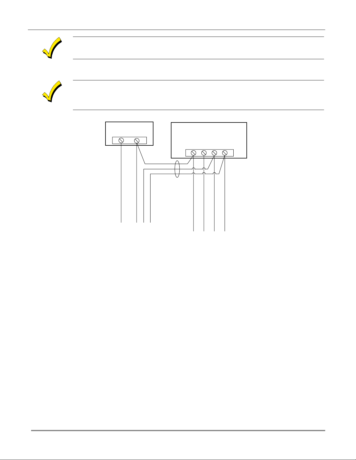
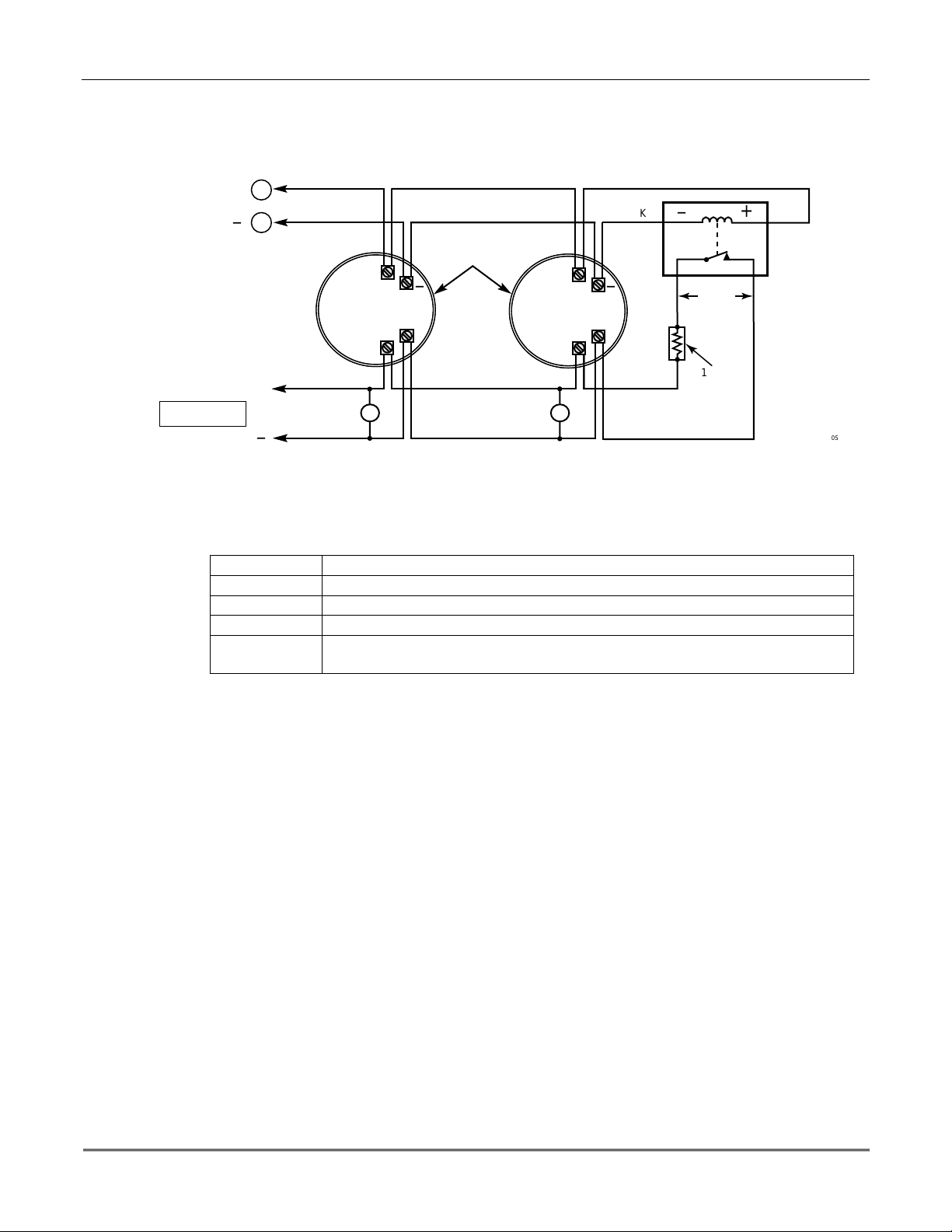
Connect the additional keypads as shown in Figure 6, using the keypad wire colors shown. Be
sure to observe the current ratings for the power supply used.
Make connections directly to the sc rew terminals as shown in
Figure 6
. Make no connection to
the keypad blue wire (if present).
Be sure to connect the negative (–) terminal on the Power Supply unit to ter minal 4 (AUX – ) on
the control.
SUPPLEMENTARY
POWER SUPPLY
+
–
TO KEYPAD RED WIRE
TO KEYPAD BLK WIRE
TO KEYPAD GRN WIRE
IMPORTANT:
MAKE THESE
CONNECTIONS
DIRECTLY TO
SCREW
TERMINALS AS
SHOWN.
TO KEYPAD YEL WIRE
CONTROL TERMINAL STRIP
AUX. DATA
AUX.
+
–
456 7
TO KEYPAD BLK WIRE
DATA
IN
OUT
TO KEYPAD RED WIRE
TO KEYPAD GRN WIRE
TO KEYPAD YEL WIRE
V10SE-008-V0
Figure 6. Using a Supplementary Power Supply for Keypads
Preliminary Checkout Procedure
If you want to check that the system is working before connecting field wiring from zones and
devices, do the following:
1. Temporarily connect a 1000 ohm end-of-line resistor across each of the basic hardwire
zones 1–6, as shown in the Summary of Connections diagram.
Without actual zone wiring or EOL resistors connected, the key pads in the system will not
display the “Ready” message.
2. Power-up the system temporar ily by plugging the AC transformer (previously wired to the
control) into a 120VAC outlet.
–
3. Busy
After approximately 1 minute*, the green READY LED (or POWER LED on some types of
keypads) should light, and the word "
"
DISARMED...READY TO ARM"
is functioning properly.
* To bypass the 1-minute delay, press # + 0.
Standby (on alpha keypads) or
dI
(on fixed-word keypads) will be displayed.
READY"
(on fixed-word keypads) or the words
(on alpha keypads) sh o uld be di splay e d, ind ica ting the sy ste m
3-3

VISTA-10SE Installation and Setup Guide
If the “Ready” message is not displayed on any of the keypads in the system, or a “Not
Ready” message is displayed, check the keypad wiring connections, and make sure each of
the 6 basic hardwired zones has a 1000 ohm resistor connected across its terminals.
Do not remove the EOL resistors until you are ready to make connections to the hardwired
zones, to allow for testing later in the manual.
If an OC or OPEN CIRCUIT display is present on the keypad, data from the control is not
reaching the keypad. Check the wiring.
3-4

SECTION 4
Basic Hardwired Zones 1–6
••••••••••••••••••••••••••••••••••••••••••••••••••
In This Section
Installing the Hardwired Zones
♦
Programming Hardwired Zones
♦
••••••••••••••••••••••••••••••••••••••••••••••••••
Installing the Hardwired Zones
Common Characteristics for Zones 1–6
•
Response time from 300 - 500 milliseconds (400 milliseconds nominal).
•
Zone 3 can be programmed (in field
(10mSec max) to an open (suitable for vibration type contacts). Default response is
400mSec nominal, which should be used for most standard contacts.
•
EOLR supervised zones support both open-circuit and closed-circuit devices.
•
As many 4-wire smoke detectors as can be powered from Aux Power on the control (on
zone 5).
52) for normally-closed sensor fast response
✱
U
L
Wiring Burglary and Panic Devices to Zones 1–6
Wiring 4-Wire Smoke/Combustion Detectors on Zone 5
4-Wire Smoke/Combustion detectors are
To wire burglary and panic devices to zones 1-6, perform the following steps, referring to
Figure 17. VISTA-10SE Summary of Connections
1. Connect sensors/contacts to the hardwired zone terminals (8 through 16). See the
Summary of Connections diagram.
2. Connect closed circuit devices in series i n the high (+) side of the loop. The EOL resistor
must be connected in series with the devices, following the last device. See the Summary
of Connections diagram.
3. Connect open circuit devices in parallel across the loop. The 1000 ohm EOLR must be
connected across the loop wires
If the EOLR is not at the end of the loop, the zone will not be properly supervised, and the
system may not respond to an open circuit on the zone.
The system will support as man y 4-wire detectors as can be pow ered from Auxiliary Po wer
on the control on zone 5. Refer to the detector’s instructions for complete d etails re g arding its
proper installation a nd operation.
1. Co nnect 12-volt power for th e detectors from Auxiliary Power terminals 4 and 5 (which
will interrupt power for fire alarm reset). Observe proper polarity when connecting
detectors. See
2. Connect detectors (including heat detectors, if used) across terminals of zone 5. All
detectors must be wired in parallel.
Figure 7
.
not
at the last device.
permitted in UL installations.
on the inside back cover of this manual.
Remove 1000 ohm EOL resistor if connected across the zone terminals. You mus t connect the
EOL resistor across the loop wires at the last detector.
4–1
VISTA-10SE Installation and Setup Guide
3. To meet NFPA 72 requirements, you must use a supervisory module to supervise power
(e.g., System Sensor No. A77-716B Relay module).
5
AUX PWR
OUTPUT
TERMINALS
+
_
4
+
TO HI SIDE OF
ZONE 5
TO LO SIDE
+
HEAT
DETECTOR
_
Figure 7. 4-wire Smoke Detector Connections (Zone 5)
4-WIRE SMOKE
OR COMBUSTION
DETECTORS
_
DETECTOR
HEAT
BLK
+
_
_
VIOLET
1000
OHMS
EOLR
+
RED
EOL
POWER
SUPERVISION
RELAY MODULE
A77-716B
V10SE-010-V0
Compatible System Sensor 4-Wire Smoke/Combustion Detectors
1412
2412
2412TH
A77–716B
2112/24T
4-wire ionization products of combustion detector
4-wire photoelectric smoke detector
4-wire photoelectric smoke detector w/135°F (57°C) heat detector
EOL relay module (supervisory module for wired 4-wire fire zone)
Low-profile 4-wire photoelectric smoke detector w/135°F (57°C) heat
detector
Programming Hardwired Zones
Each zone must be programmed into the system using the ✱56 Zone Programming Mode or
✱
58 Expert Programming Mode, which assigns characteristics that define the way the system
responds to faults on that zone. Refer to the ZONE RESPONSE TYPE DEFINITIONS and
ZONE PROGRAMMING sections for specific instructions on programming hardwired zones.
4-2

SECTION 5
Wireless Expansion
••••••••••••••••••••••••••••••••••••••••••••••••••
(5800 System)
In This Section
About Wireless Expansion
♦
Installing the 5881/5882 Receiver
♦
Installing the 5800TM Module
♦
••••••••••••••••••••••••••••••••••••••••••••••••••
About Jam Detection and Reporting
♦
5800 Series Transmitters
♦
Installing 5800 Series Transmitters
♦
About Wireless Expansion
The VISTA-10SE supports up to 16 wireless zones that may be used exclusively or in
addition to hardwired zones 1 through 6.
The receiver detects signals from
The following 5881 Receivers may be used with this system (5882 in Canada), and each
supports the number of zones shown:
RF Receiver No. of Zones
5881L/5882L up to 8
5881M/5882M up to 16
5881H/5882H up to 16
wireless transmitters
within a nominal range of 200 feet.
U
L
Receiver Supervision
House Identification
Wireless may not be used in UL Commercial Burglary installations.
In Canada
Series of receivers applies as well to the 5882 Series. 5881 and 5882 Series receivers can
support the same 5800 type transmitters.
Any zone
with the number of zones that can be used, which is shown in table above).
The receiver is supervised. The following conditions cause a Trouble report to be generated
and CHECK and ZONE 09 messages to be displayed:
•
Communication between the panel and the receiver is interrupted.
or
No
•
If you are using a 5804BD, 5827, or 5827BD Wireless Keypad with the system, you must
program a House ID Code (01-31) in field
must be set to the same ID.
12 hours.
valid
, 5800 systems must use 5882 Series receivers. Information relative to the 5881
number
from 10–25 can be used as a 5800 Series wireless zone (do not confuse this
RF signals from at least one supervised wireless transmitter are received within
✱
24 to establis h proper communication. The keypad
House ID 00 disables all wireless keypads.
5–1
VISTA-10SE Installation and Setup Guide
Installing the 5881/5882 Receiver
RF System Installation Advisories
Follow the guidelines below when installing the RF receiver. (Disregard if the receiver is
mounted in the control cabinet.)
Installation and Setup of the 5881/5882 Receiver
ON OFF
5
4
3
2
1
Place the
•
Do not locate the receiver or transmitters on or near metal objects. This decreases range
•
RF receiver
in a high, centrally located area for best reception.
and/or block transmissions.
Do not locate the receiver in an area of high
•
interference (revealed by frequent or
RF
prolonged lighting of the LED in the receiver; random flicker is OK).
The RF receiver must be at least 10 feet from any remote keypads to avoid interference
•
from the microprocessors in those units.
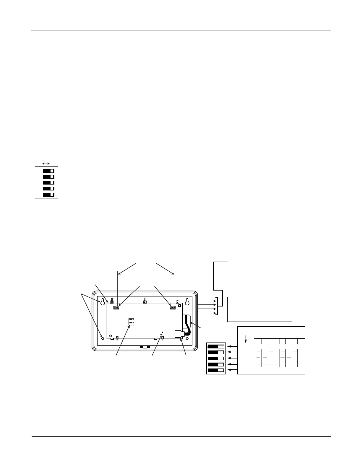
To install the recei ver, take the following steps (refer to
1. Set the receiver's
< <
switches shown at l eft are in the OFF posit ion).
DIP switch
for device address 0, as described in its instructions (all
Figure 8
below):
2. Mount the receiver. The RF receiver can detect signals from transmitters within a
nominal range of 200
feet
. Take this into consideration when determining mounting
location.
3. Connect the
receiver's
wire harness to the control's keypad terminals (4, 5, 6, and 7). Plug
the connector at the other end of the harness into the receiver.
4. Refer to the
installation
instructions provided with the receiver for further installati on
procedures regarding antenna mounting, etc.
MOUNTING
HOLES
CIRCUIT
BOARD
ANTENNAS
INSERT IN
RIGHT-HAND
TERMINALS
DIP SWITCH
DIP SWITCH #5 (PRESET ONLY ON 5881EH)
ON: SETS 5881EH FOR USE IN COMMERCIAL
FIRE APPLICATIONS (SEE THE RECEIVER'S
INSTRUCTIONS)*.
OFF: USE IN NON-COMMERCIAL FIRE
INSTALLATIONS.
* FOR COMMERCIAL FIRE APPLICATIONS
THE 5881EH PC BOARD MUST BE MOUNTED
IN A SEPARATE CABINET (SEE RECEIVER'S
INSTRUCTIONS FOR DETAILS).
INTERFERENCE
INDICATOR LED
PLUG & SOCKET
YELLOW
RED
BLACK
GREEN
WIRING
OPENING
TO CONTROL'S REMOTE KEYPAD
CONNECTION POINTS. EACH RECEIVER
MUST BE ON INDIVIDUAL HOME RUN.
USE MAX. of 220 ft. [67m of #22 (0.64mm)
WIRE or 550 ft. (168m) of #18 (1mm) WIRE
FOR EACH RUN]. OBSERVE 20 ft. MAX.
FOR COMMERCIAL FIRE INSTALLATIONS.
(SEE RECEIVER'S INSTRUCTIONS.)
DIP SWITCH WHITE AREAS = SWITCH
HANDLES. POSITIONS 2-4 DETERMINE
RECEIVER'S ADDRESS. CONSULT
CONTROL'S INSTRUCTIONS FOR
ADDRESS TO USE. DIP SWITCH BELOW
SHOWN SET FOR ADDRESS "0."
SWITCH
POSITION
Figure 8. 5881/5882 RF Receiver (cover removed)
RECEIVER ADDRESS SETTINGS
(" - " MEANS OFF)
0 1 2 3 4 5 6 7
PRESENT ONLY ON 5881EH (SEE TEXT AT LEFT)
5
4
3
2
1
ON ON ON
ON
ONON
FOR FUTURE USE
ONON
ONON ONON
5-2

Installing the 5800TM Module
Installation of this module is necessary only if you are using one or more 5827BD Wireless
Bi-directional keypads, 5804 or 5804BD Transmitters (wireless keys).
Mounting the 5800TM Module
The 5800TM must be located next to the RF receiver (between one and two feet from the
receiver’s antennas). The 5800TM must not be installed within the control cabinet. Mount
the unit using its accompanying mounting bracket.
Wiring the 5800TM Module
Connect the 5800TM to the control panel’s keypad connection terminals, using the supplied
connector with flying leads, as follows:
Wire Terminal on Control
BLACK (Ground) Terminal 4
RED (+12VDC) Terminal 5
GREEN (Data to Control) Terminal 6
YELLOW (Data from Control) Terminal 7
BLUE Not Used
Do not cut any of the jumpers on the 5800TM when using it with the VISTA-10SE.
For additional information, refer to the 5800TM’s instructions.
Section 5 - Wireless Expansion
About Jam Detection and Reporting
When field ✱22, option 4 (RF SYSTEM) is selected, a 5800 Series receiver detecting a jam
condition sends an E344 (RF Receiver Jam Detect) Contact ID report to the central station.
At the same time, a Rcvr Jam (on alpha keypads) or CHECK 90 (on fixed-word keypads)
message alternates with the present system message on the keypad. When the jam condition
is cleared, a Restore message is sent to the CS. Entering a code and OFF restores the
keypad display.
The default for this option is 0 (disabled).
Normal use of a 5827 wireless keypad may cause a false RF jam message to be displayed in
systems that have been programmed for RF Jam Detection.
5800 Series Transmitters
Programming Wireless Zones
5800 Series transmitters have built-in serial numbers that must be enrolled” into the system
✱
using the
the control via the downloader. 5800 Series transmitters (except 5827, described separately)
do not have DIP switches.
Program each transmitter's zone number into the system using
Zone Programming section). Some transmitters, such as the 5816 and 5817, can support
more than one “zone” (referred to as loops or inputs). On the 5816, for example, the wire
connection terminal block is loop 1, the reed contact is loop 2. Each loop must be assigned a
different zone number.
56 or ✱58 programming modes in the ZONE PROGRAMMING section, or input to
✱
56 or ✱58 mode (refer to the
U
L
The 5816 and 5817 transmitters do not have EOL supervision of their loop wiring. Therefore, for
UL Household Burglary installations, the loop wiring may not exceed 3 feet.
5-3
VISTA-10SE Installation and Setup Guide
For button transmitters (RF keys), such as the 5801, 5804, and 5804BD, you must assign a
unique zone number to each individual button used on the transmitter. Each button on the
transmitter also has a pre-designated loop or input number, which is automatically displayed
on the keypad.
Programming an RF House ID
Programming an RF House ID (01–31) in field
5827BD Wireless Keypads or 5804BD Transmitters. An RF House ID is not necessary for
other 5800 Series Transmitters, and the entry should be left at 00 (default) in those cases.
The 5827 reports low-battery status as zone 00.
Transmitter Supervision
Except for some transmitters that may be carried off-premises (5802, 5802CP, 5803, 5804,
5804BD, 5827, and 5827BD), each transmitter is supervised by a check-in signal that is sent
to the receiver at 70-90 minute intervals. If at least one check-in is not received from each
supervised transmitter within a 12-hour period, the “missing” transmitter number(s) and the
message CHECK is displayed.
In accordance with ULC standards, the RF supervision period for the VISTA-10SE is three hours
for fire zones (Zone Type 9) and 12 hours for all other zone types.
✱
24 is necessary only if you are using 5827 or
The supervision for a particular transmitter in the system that may also be carried off the
premises (5801, 5802MN) may be turned off by enrolling it as a “UR” (unsupervised RF) type,
as described later.
5800 Series transmitters have built-in tamper protection and annunciate as a Check
condition if covers are removed.
Transmitter Input Types
All of the transmitters described have one or more unique, factory-a ssigned input (loop) ID
codes. Each of the inputs requires its own programming zone (for example: a 5804's four
inputs require four programming zones). Refer to the ZONE PROGRAMMING section.
Transmitters can be enrolled as one of the following types:
Type Description
RF
(Supervised RF)
UR
(Unsupervised RF)
BR
(Unsupervised Button RF)
Transmitter Battery Life
Sends periodic check-in signals, as well as fault, restore, and lowbattery signals. The transmitter must remain within the receiver's
range.
Sends all the signals that the “RF” type does, but the control does
not supervise the check-in signals. The transmitter may therefore be
carried off-premises.
Sends only fault signals. It will not send a low-battery signal until it is
activated. The transmitter may be carried off-premises.
5-4
Do not install batteries in wireless transmitters until you are ready to enroll the transmitters
during system programming. After enrolling, batteries need not be removed.
Batteries in the wireless transmitters may last from 4 to 7 years, depending on the
environment, usage, and the specific wireless device being used. Factors such as humidity,
extreme temperatures, as well as large temperature variations may all reduce the actual
battery life in a given installation.

The wireless system can identify a true low-battery situation, thus allowing the dealer or
user of the system time to arrange a change of battery and maintain protection for that point
within the system.
Some transmitters (e.g., 5802, 5802CP, and 5804) contain long-life but nonreplaceable
batteries, and no ba ttery installati on is required. At the end of their life, the complete unit
must be replaced (and a new serial number enrolled by the control).
Button-type transmitters (such as 5801, 5802, 5802MN/MN2, 5802CP, and 5804) should be
periodically tested for battery life.
The 5802MN and 5804 Button Transmitters have replaceable batteries.
Using the Transmitter Sniffer Mode
The Transmitter Sniffer mode is a procedure that verifies that all transmitters have been
properly programmed. To verify programming, refer to the TESTING THE SYSTEM section.
5800 Series Transmitters Table
Model Description Input Type and Special Notes
5801 Wireless Panic
Transmitter
5802
5802CP
5802MN
5802MN
5804
5804BD
5806
5807
5808
5807L
5807LT
5807LST
5808LST
5809
5816
5816MN
5816
5817 Multi-Point Universal
Pendant Belt Clip
(Personal Emergency)
Transmitters
Miniature Personal
Emergency Trans.
2
Wireless Key
Transmitter
Wireless Photoelectric
Smoke Detectors
Low-profile version
of the Wireless
Photoelectric Smoke
Detectors
HeatSensor, 135
Detector/Transmitter
Door/Window
Transmitter
TEMP
Low Temp Sensor
Transmitter
º
Enroll as “3” for RF (supervised), or “4” for UR (unsupervised).
Unit has 4 pushbuttons, each with a unique input (loop) code.
Each pushbutton must be assigned to a zone.
Input loop (button) No. 4 must always be used.
NOTE:
Enroll as “5” for BR (button-type transmitter).
Enroll as “3” for RF (supervised), or “4” for UR (unsupervised).
Single pushbutton-type transmitter.
Enroll as “5” for BR (button-type transmitter).
Has 4 pushbuttons, each with a unique input (loop) code.
Each pushbutton must be assigned to a zone.
All buttons must be assigned the same input type.
NOTE:
Enroll as “3” for RF (supervised).
At the “INPUT S/N” prompt, fault the detector as follows:
On many detectors, you must press a special test switch (not test button) to
1.
fault the
NOTE:
detector. Disengage the detector’s cover and swing it open. These contacts
are on the PC board near a blue jumper (see detector’s instructions).
Momentarily short these contacts with a small screwdriver.
Two keypad beeps occur when the detector is faulted the first time.
Wait 6 to 8 seconds, then press and release the test switch (or momentarily
2.
short the contacts) again. If the control has accepted the input code, 3 beeps
sound and the enrolled input (loop) number is displayed.
Enroll as “3” for RF (supervised).
Has two unique input (loop) zones: one for a wired closed-circuit contact loop,
and the other for a built-in reed switch (used in conjunction with a magnet).
Either or both may be used.
Enroll as “3” for RF (supervised).
Has three unique input (loop) codes: one for a DIP switch-set “Primary” contact
loop, and the others for two “Auxiliary” closed-circuit contact loops.
The “Primary” loop may be set for:
•
•
•
3-Minute or no Transmission Inhibit
detector
With some detectors, you must short two contacts to fault the
Repeating or Single Transmission
Normally Open or Normally Closed circuit
Slow or Fast Response
(see detector’s instructions).
Section 5 - Wireless Expansion
5-5
VISTA-10SE Installation and Setup Guide
5800 Series Transmitters Table (
Model Description Input Type and Special Notes
5817
(cont'd.)
Multi-Point Universal
Transmitter
(cont'd.)
5818 Recessed Magnetic
Contact Transmitter
5819
5819
5819
5849
5850
Shock Processor
Transmitter
BRS
WHS
Glassbreak
Detector/Transmitter
5852
5890
5890P1
PIR Detector/
Transmitter
DIP Switches:
All loops must be assigned the same input type.
NOTE:
Enroll as “3” for RF (supervised).
Enroll as “3” for RF (supervised).
Has three unique input (loop) zones: one for a wired closed-circuit contact loop,
one for use with inertia-type shock detectors (mounted externally), and one for a
built-in reed switch (used in conjunction with a magnet).
Enroll as “3” for RF (supervised).
Enroll as “3” for RF (supervised).
The cover must be on the unit when enrolling the serial number.
Set all DIP switches to the OFF position when enrolling the
serial number.
When “enrolling” a transmitter’s ID code(s), any PIR in the vicinity that is not being enrolled
should be covered with a cloth, tissue, etc. to prevent activation.
Installing 5800 Series Transmitters
To be sure reception of the transmitter's signal at the proposed mounting location is
adequate, perform a Go/No Go Test in the TESTING the SYSTEM section.
continued)
Setting DIP Switches on the 5827 Transmitter(s)
You must set a 5827 Transmitter to the programmed House ID, using its DIP switches.
SWITCH UP FOR "ON"
SWITCH DOWN FOR "OFF"
SHOWN SET FOR
HOUSE ID # 30
DIP SWITCH POSITION
12345
1 ----UP
2 ---UP3 - - - UP UP
4--UP-5--UP-UP
6--UPUP7 - - UPUPUP
8 -UP--9 - UP - - UP
10 - UP - UP 11 - UP - UP UP
12 - UP UP - 13 - UP UP - UP
14 - UPUPUP 15 - UPUPUPUP
16UP----
DIP SWITCH POSITIONHOUSE
ID
17 UP - - - UP
18 UP - - UP 19 UP - - UP UP
20 UP - UP - 21 UP - UP - UP
22 UP - UP UP 23 UP - UPUPUP
24 UP UP - - 25 UP UP - - UP
26 UP UP - UP 27 UP UP - UP UP
28 UP UP UP - 29 UP UP UP - UP
30 UP UP UP UP 31 UP UP UP UP UP
12345
5-6
SECTION 6
Relay Output Devices
••••••••••••••••••••••••••••••••••••••••••••••••••
In This Section
Relay Device Basics
♦
4204 Relay Modules
♦
Programming Options
♦
••••••••••••••••••••••••••••••••••••••••••••••••••
Relay Device Basics
Relays are programmable switches that can be used to perform many different functions.
They can be used to turn lights on and off, control sounders, or for status indications. In this
system, each relay must be programmed as to how to act (ACTION), when to activate
(START), and when to deactiva te (STOP). Each of these is described below.
The control supports a total of 4 output relays.
The 4204 Relay modules provide Form C (normally open and normally closed) contacts.
In ✱80 and ✱81 interactive modes, a series of keypad prompts will request entries for
programming of the Relay outputs used in the system. Refer also to “OUTPUT RELAY
✱
DEVICE WORKSHEET FOR
80 AND ✱81 INTERACTIVE MODES” in the blank
programming form provided in the separate Programming Form manual.
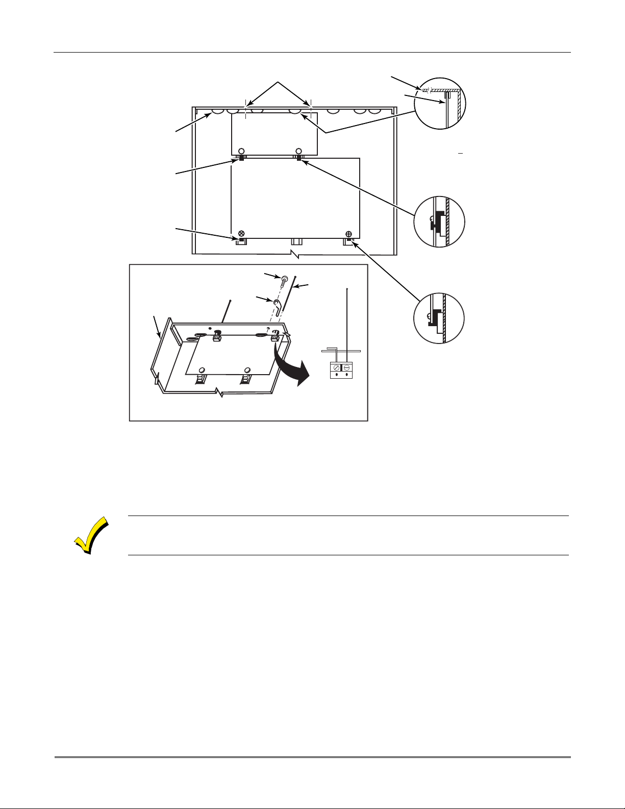
4204 Relay Modules
4204 Relay Unit (if installed in cabinet)
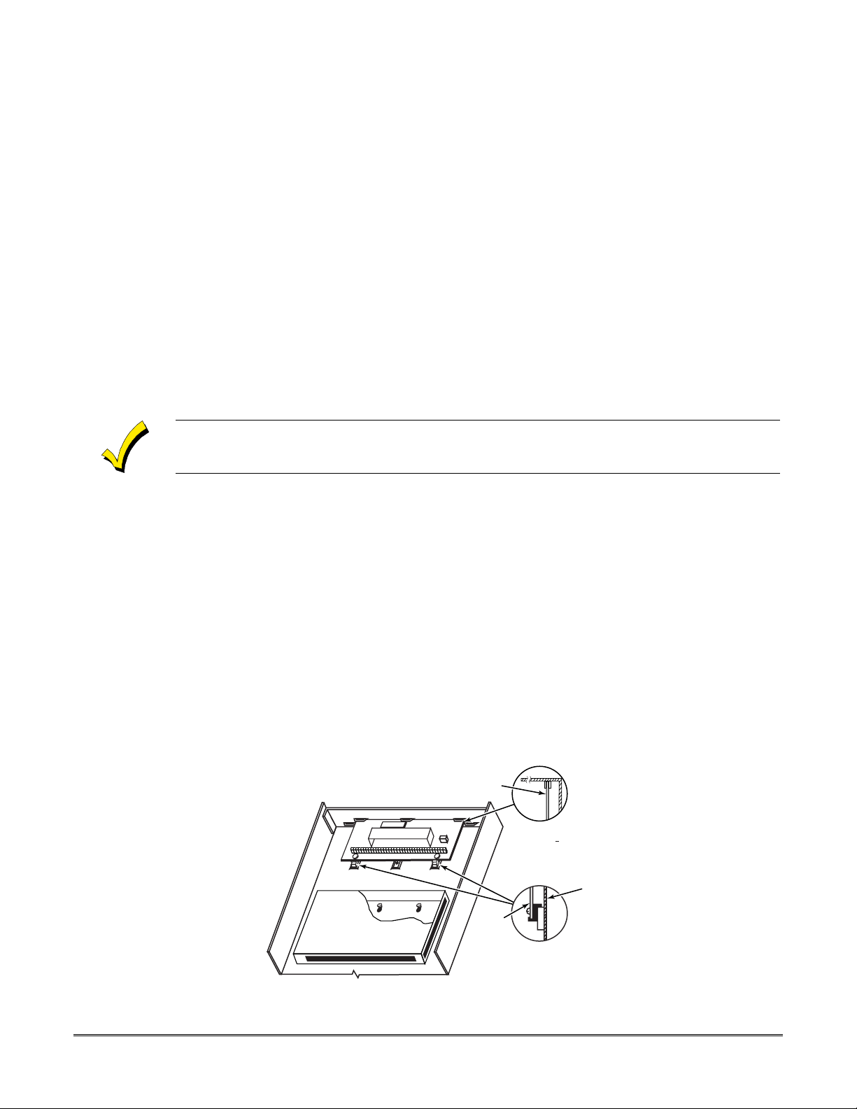
1. Insert self-tap pin g screw s (prov ide d ) in two adj ace nt raise d cabin e t tabs. Leav e the he ads
projecting 1/8".
2. Hang the unit on the screw heads via two of the slotted holes at the rear of its housing, as
shown in
Figure 9
below.
3. The 4204's co ver can be left o ff if the u nit's DIP switch is set with its p osition 1 "ON" (to
the right) as shown in its instructions. The tamper-protected cover is necessary for
installations outside of the control's ca binet.
+
Figure 9. Mounting the PC Board in the Cabinet with a 4204 Relay Unit
CIRCUIT BOARD
+
CIRCUIT
BOARD
DETAIL A
SIDE VIEW
OF BOARD
SUPPORTING
SLOTS
DETAIL B
SIDE VIEW
OF MOUNTING
CLIPS
CABINET
V10SE-003-V0
6–1
1 2 3 4 5
OFF ON
ON
@@@@@@@@e?
@@@@@@@@e?
@@h?
@@h?
@@h?
@@h?
@@h?
@@h?
@@@@@@@@e?@@@@@@@@?e@@@@@@@@e?@@@@@@@@?e@@@@@@@@e?@@@@@@@@?e@@@@@@@@e?@@@@@@@@?e
@@@@@@@@e?@@@@@@@@?e@@@@@@@@e?@@@@@@@@?e@@@@@@@@e?@@@@@@@@?e@@@@@@@@e?@@@@@@@@?e
@@@@@@@@
@@@@@@@@
@@
@@
@@
@@
@@
@@
@@
@@
@@
@@
@@
@@
@@
@@
@@
@@
@@
@@
@@
@@
@@
@@
@@
@@
@@
@@
@@
@@
@@
@@
@@
@@
@@
@@
@@
@@
@@
@@
@@
@@
@@
@@
@@
@@
@@
@@
@@
@@
@@
@@
@@
@@
@@
@@
@@
@@
@@
@@
@@
@@
@@
@@
@@
@@
@@
@@
@@
@@
@@
@@
@@
@@
@@
@@
@@
@@
@@
@@
@@
@@
@@
@@
@@
@@
@@
@@
?@@
?@@
?@@
?@@
?@@
?@@
?@@@@@@@@
?@@@@@@@@
?@@@@@@@@?e@@@@@@@@e?@@@@@@@@?e@@@@@@@@e?@@@@@@@@?e@@@@@@@@e?@@@@@@@@?e@@@@@@@@
?@@@@@@@@?e@@@@@@@@e?@@@@@@@@?e@@@@@@@@e?@@@@@@@@?e@@@@@@@@e?@@@@@@@@?e@@@@@@@@
@@g
@@g
@@g
@@g
@@g
@@g
@@@@@@@@
@@@@@@@@
@@
@@
@@
@@
@@
@@
@@
@@
@@
@@
@@
@@
@@
@@
@@
@@
@@
@@
@@
@@
@@
@@
@@
@@
@@
@@
@@
@@
@@
@@
@@
@@
@@
@@
@@
@@
@@
@@
@@
@@
@@
@@
@@
@@
@@
@@
@@
@@
@@
@@
@@
@@
@@
@@
@@
@@
@@
@@
@@
@@
@@
@@
@@
@@
@@
@@
@@
@@
@@
@@
@@
@@
@@
@@
@@
@@
@@
@@
@@
@@
VISTA-10SE Installation and Setup Guide
4204 Setup
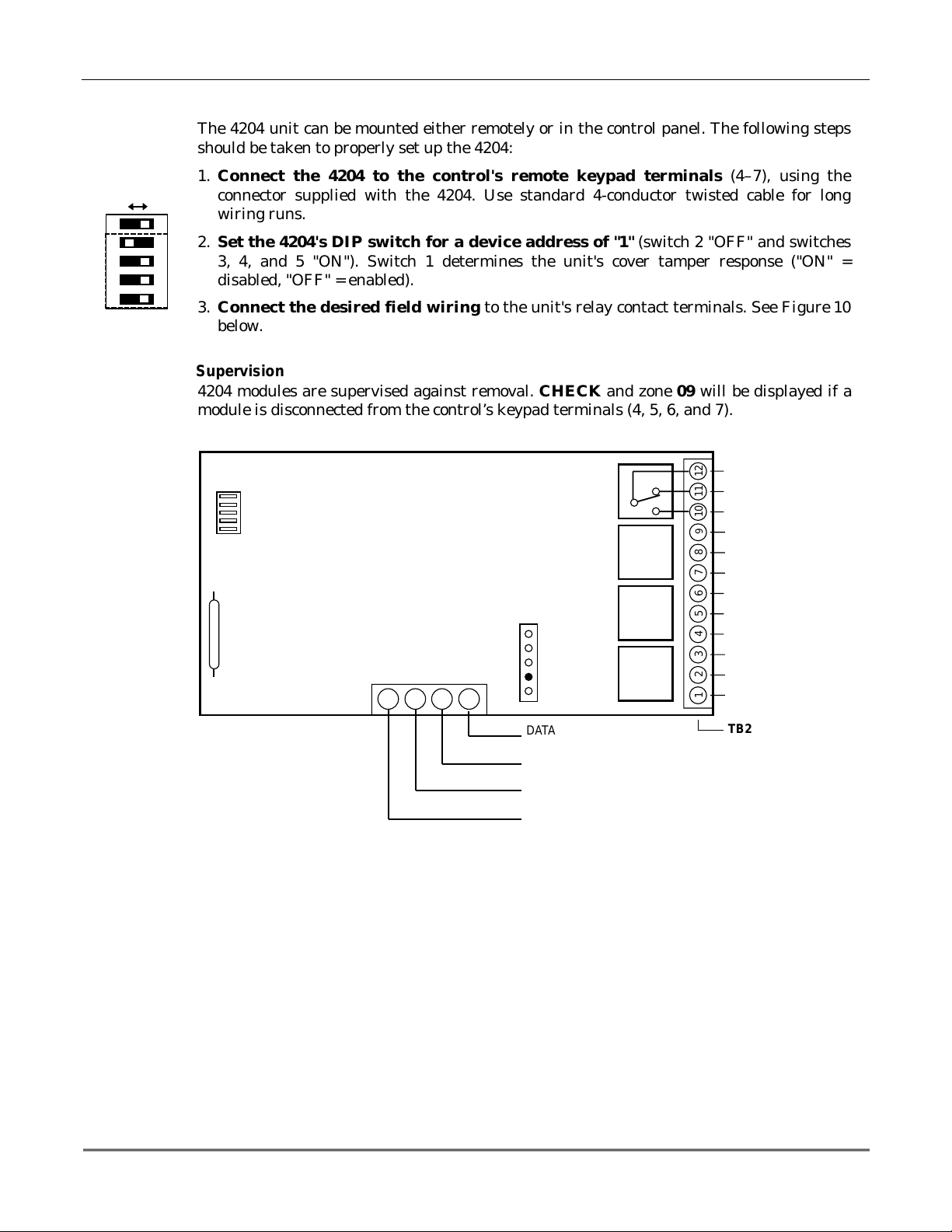
The 4204 unit can be mounted e ither remote ly or in the control p anel. The follo wing ste ps
should be taken to properly set up the 4204:
1. Connect the 4204 to the control's remote keypad terminals (4–7), using the
connector supplied with the 4204. Use standard 4-conductor twisted cable for long
wiring runs.
2. Set the 4204's DIP switch for a device address of "1" (switch 2 "OFF" and switches
3, 4, and 5 "ON"). Switch 1 determines the unit's cover tamper response ("ON" =
disabled, "OFF" = enabled).
3. Con nect the des ired fie ld wiri ng to th e unit's r elay c ontact te rmin als. See Figure 10
below.
Supervision
4204 modules are supervised against removal. CHECK and zon e 09 will be displayed if a
module is disconnected from the control’s keypad terminals (4, 5, 6, and 7).
4204
DIP SWITCH
FOR SETTING DEVICE ADDRESS
AND ENABLING/DISABLING TAMPER
COVER T AMPER (REED) SWITCH
Programming Options
RELAY
4
TYPICAL
(SHOWN "OFF")
4-PIN KEYPAD PLUG
EITHER OR BOTH
CAN BE USED
TB1
13 14 15 16
YEL
BLK
GRN
RED
Figure 10. 4204 Connections to Control
DATA I N
FROM CONTROL
(–) GROUND
DATA OUT
TO CONTROL
(+) 12V
RELAY
3
RELAY
2
RELAY
1
C
121110
NC
NO
9
C
87654321
NC
NO
C
NC
NC
NO
C
NC
NO
TB2
V10SE-016-V0
6-2
In the VISTA-10SE, each device must be programmed as to how to act (ACTION), when to
activate (START), a n d when to de-activate (STOP). Refer to t he programming procedures for
✱
80 and
✱
81 interactive modes that are provided in the MECHANICS of PROGRAMMING,
OUTPUT DEVICE PROGRAMMING, and ZONE LISTS sections for specific programming
details.

SECTION 7
4285 and 4286 VIP Module
••••••••••••••••••••••••••••••••••••••••••••••••••
In This Section
Installing the VIP Module
♦
Programming the 4285/4286 VIP Module
♦
••••••••••••••••••••••••••••••••••••••••••••••••••
Checking 4285/4286 VIP Module Operation
♦
Installing the (Voice Interactive Phone) Module
General Information
The 4285/4286 VIP Module is an add-on accessory for the VISTA–10SE that permits access to
the security system via a TouchTone phone (either on premises or by a call-in when away).
The VIP Module can announce many of the same words that would normally be displayed on
an alpha keypad under the same system conditions.
When using the VIP Module, addressable keypads must be used in the system, but set to the
non-addressable mode (address 31); i.e., do not use a 6127 keypad.
When properly connected, the VIP Module will enable the user to do the following via a
TouchTone telephone:
•
Receive synthesized voice messages over the phone regarding the status of the security
system.
•
Arm and disarm the security system and perform most other commands using the
telephone keypad, with voice annunciation provided over the phone as confirmation after
a command is entered.
The phone used f or p ho ne acce ss must h ave To uc hTo ne capability , tho u gh Tou ch Ton e se rv ice
is not necessary (if premises uses PULSE dialing, switchable phones must be set for
TouchTone temporarily before attempting phone access).
A Pho ne Access User's Guide for phone access to the security system is provided with the
VIP Module for the user of the system.
U
L
Mounting the VIP Module
The VIP Module is not Listed for UL installation use
The VIP Module may be mou nted in the control cabine t if space is available or, if th is is not
possible, on the side of the cabinet or adjacent to it.
When mounting the VIP Module outside the cabinet, use the screw holes at its rear. That will
permit it to be mounted horizontally or vertically (double-sided tape may be used, if
preferred). Wires can be bro ug ht o ut f ro m th e sid e or back (a ro un d bre ako ut is also available
on the back).
Affix the VIP Module’s connections label (supplied separately) to the inside of the VIP
Module's cover if the cover is used. If yo u have installed th e module within the cabinet, affix
the label to the ins ide of the control cabinet's door.
.
7–1
VISTA-10SE Installation and Setup Guide
VIP Module Wiring
The VIP Module is wired between the control panel and the premises handset(s). It listens
for touch-tones on the phone line and reports them to the control panel. During on-premises
phone access, it powers the premises phones; during off-premises phone access, it seizes the
line from the premises phones and any answering machines.
NOTE: The phone lines must be in service for the VIP Module to function, even when
accessing the system from an on-premises phone.
1. Make 12V (+) an d (–) and data in and data out connections from the VIP Module to the
control, using the connector cable supplied with the VIP Modul e (see Figure 10).
Color Lead Terminal On Control
GREEN DATA IN (terminal 6)
BLACK AUX – (terminal 4)
RED AUX + (terminal 5)
YELLOW DATA OUT (terminal 7)
2. Insert the keyed connector at the other end of the connector cable into the mating header
on the VIP Module (see diagram on next page for location of the header).
*
*
These are the same connections
as those used for remote
keypads
.
3. Conne ct terminals 1 through 4 on the VIP Module as shown in the Wiring Table and in
the 4285/4286 wiring diagram that follows.
Use an RJ31X jack with a direct-connect cord and make all connections exactly as shown. If
the leads on the direct-connect cord are too short to reach their assigned terminals, splice
additional wires to them, as required.
4285/4286 WIRING TABLE
4285/4286/4286
Terminal
Phone In (Tip)
1.
Phone In (Ring)
2.
Phone Out (Tip)
3.
Phone Out (Ring)
4.
NOT USED
5.
Output High
6.
Output Rtn
7.
If no touch-tones are produced following access to the security system
Connects to:
Terminal (17) on control.
Terminal (18) on control.
BROWN lead from direct-connect cord.
GRAY lead from direct-connect cord.
——
Not used (4285). Spkr High on 4286.
Not used (4285). Spkr Return on 4286.
from on-premises
(this
problem may arise in rare cases), it may be necessary to reverse the wires connected to
terminals 3 and 4 on the VIP Module
control.
Figure 11
shows the wiring connections that will provide proper operation in most
and
the wires connected to terminals (17) and (18) on the
cases.
7-2
Caller ID Units
If the telephone system on the premises includes a Caller ID unit, connect the ID unit
directly to the “Handset” terminals (17 and 18) on the control, as shown in Figure 11.
Section 7 - 4285/4286 VIP Module
4285/4286 VIP Module WIRING NOTES:
1.
Wire the VIP Module exactly as shown, using a direct-connect cord and RJ31X jack.
2.
If you do no hear tones when pressing keys after accessing the security system via an on-premises
phone, try reversing the pair of wires connected to terminals 3 and 4 on the VIP Module
pair of wires connected to terminals 17 and 18 on the control.
3. If you hear an error signal (fast busy signal) when trying to access the system via the phone, check
for correct line se izure wiring, as described in note 4.
4. Connection to the incoming telco line via a RJ31X jack and direct-connect cord, as shown in this
diagram, is essential, even if the system is not connected to a central station.
The 4285 or 4286
will not function if this is not done.
The house phone lines (gray and brown wires) must be wired to the VIP Module
terminals, not to the control terminals. Otherwise, an error signal (fast busy signal) will
occur when you try to access the system from an on-premises phone.
5. If the telephone system on the premises includes a Caller ID unit, connect the unit
“Handset” terminals (17 and 18) on the control, as shown.
and
directly
the
to the
TERMINALS
ON CONTROL
CALLER ID
UNIT
IMPORTANT NOTE FOR
EXISTING INSTALLATIONS:
EXISTING WIRES
CONNECTED TO THE
"HANDSET" TERMINALS ON
CONTROL MUST BE MOVED
FROM THERE TO TERMINALS
3 AND 4 ON THE 4285.
4285/4286
VIP MODULE
SPEAKER VOLUME
ADJUSTABLE ON
4286 ONLY
KEYED
HEADER
UNUSED
CONNECTOR
WITH FLYING
LEADS
YELLOW: TO DATA OUT (term. 7)
NO CONNECTION
RED: TO AUX (+) (term. 5)
BLACK: TO AUX. GROUND (–) (term.4)
GREEN:
Handset
{
17
1
MUST CONNECT TO
ON 4285 (TIP)
TO DATA IN (term. 6)
Incoming
Teleco Line
{
19
18
2
GREEN (TIP)
ON 4285 (RING)
MUST CONNECT TO
12345 6 7
20
21
DIRECT
CONNECT
CORD
RED (RING)
PLUG
GREY (R)
BROWN (T)
CONNECTION
TO CONTROL
PANEL
TERMINALS
USED FOR
KEYPAD
CONNECTIONS
GROUND
NO
TO EARTH GROUND (COLD WATER PIPE, ETC.)
INCOMING TELCO LINE
TIP
RING
TIP
RJ31X
RING
JACK
CA38A
IN
CANADA
PREMISES ANSWERING
MACHINE AND PHONES
ANSWERING
MACHINE
*
*
*
NOTE: IF THE TELEPHONE HAS BUILT-IN CALLER ID,
THE CALLER ID FUNCTION MAY NOT WORK
TERMINAL ASSIGNMENTS
1 - TIP
2 - RING
3 - TIP
4 - RING
5 - NO CONNECTION
6 -
}
7 -
4285/4286
PHONE INPUT
}
PHONE OUTPUT
}
AUDIO OUT
4286 ONLY
V10SE-029-V0
.
Figure 11. 4285/4286 VIP Module Wiring Connections
7-3

VISTA-10SE Installation and Setup Guide
Programming the Control for Phone Access
To program the control for phone access using the 4285/4286 VIP Module, you must assign a
✱
VIP Module access code (
26) and ring detection count (✱95). Also, you may optionally select
words and/or form custom words that would be displayed on the keypad. Refer to THE DATA
FIELD DESCRIPTION and ALPHA DESCRIPTOR PROGRAMMING sections for specific
programming details.
Perform a preliminary check of the VIP Module, as indicated next.
Checking the Operation of the VIP Module
To Check VIP Module Operation From an On-Premises Phone
1. Pick up the phone and enter the programmed 2-digit VIP Module access code.
Annunciation of a system status report should automatically start. See the User Guide
accompanying the VIP Module for detailed information regarding the nature of the status
report, if necessary.
2. During any pause in the status report, or immediately following it, key the following via
the keypad on the phone:
4111 (Installer code) + 1 (OFF).
You should hear a beep on the phone and from a wired keypad. You should als o hear the
words, "Disarmed...Ready to Arm" or "Disarmed...Not Ready to Arm," indicating that
the command was entered successfully. (The voice message, "Disarmed...Not Ready to
Arm" indicates an open zone).
3. Hang up the phone.
To Check VIP Module Operation from an Off-Premises Phone:
1. Have someone dial the premises phone number, using a TouchTone phone.
•
If the phone system does not include an answ ering machine, the caller hears 2 long
tones, followed by a voice prompt "
HELLO, ENTER PHONE CODE NOW
must enter the programmed 2-digit phone code (entered in field
MODULE ACCESS CODE)
•
If the premises phone system includes an answering machine, the 2-digit phone
.
code must be entered during a pause at the beginning of, or during, the outgoing
answering machine message. Then the caller hears a voice prompt asking for entry of
the 4-digit system code ( "
ENTER SYSTEM CODE NOW
2. The caller sh ould then enter the Installer Code ( 4111). As a safety feature , there is a 3-
try limit in which to enter each code (phone code and system code), after which time the
call-in is aborted. Also, if no keys are pressed for a period of 20 seconds, the call-in is
aborted.
Annunciation of a system status report will start if both codes were entered correctly.
3. During an y pause in the statu s report, or imme diately follo wing it, the caller sh ould key
the following via the keypad on the phone:
Installer Code (4111), then 1 (OFF).
The caller should hear a beep from the phone and a wired keypad on the premises. The
caller should also hear the words "Disarmed...Ready to Arm" or "Disarmed...Not
Ready to Arm" on the phone, indicating that the command was entered successfully.
"Disarmed...Not Ready to Arm" would indicate an open zone.
4. At this point, the caller can hang up the phone.
5. Verify with the caller that there was successful access to the system and that the
appropriate voice announcements were hea rd over the phone.
").
" The caller
.
✱
28,
PHONE)
7-4
6. If the VIP Module functioned satisfactorily, unplug the AC transformer from the AC
outlet.

SECTION 8
External Sounders
••••••••••••••••••••••••••••••••••••••••••••••••••
In This Section
Compatible Sounders
♦
NFPA Requirements
♦
Sounder Connections and Power
♦
••••••••••••••••••••••••••••••••••••••••••••••••••
Sounder Supervision
♦
Testing the Sounder
♦
Compatible Sounders
ADEMCO AB-12M 10” Motorized
Bell & Box
ADEMCO 1011BE12M 10”
Motorized Bell & Box
ADEMCO 702
Outdoor Siren
ADEMCO 719
2-Channel Siren
ADEMCO 747
Indoor Siren
ADEMCO 747UL
Indoor Siren
ADEMCO 744
Siren Driver
ADEMCO 745X3
Voice Siren Driver
ADEMCO 705–820,
5-inch Round Speaker
ADEMCO 713 Speaker
System Sensor PA400B
(beige)/PA400R (red)
Indoor Piezo Sounder
Motor bell & box. UL Grade A. 100mA current draw.
Motor bell & box. UL Listed. 100mA current draw.
Self-contained 6–12 volt siren (driver built-in) and
weatherproof for outdoor use. Can be wired for either a
steady or warble sound. 117dB @ 10 feet. 1500mA current
draw.
Self-contained 6–12-volt siren (driver built in). Steady or
warble sound. 109dB @ 10 feet. 550mA current draw.
Self-contained 6–15 volt siren (driver built-in) for indoor
wall mount. 747F available for flush mounting. 105dB @ 10
feet. 400mA current draw.
Self-contained 6–15 volt siren (driver built-in) for indoor
wall mount. UL Listed. 85dB @ 10 feet. 320mA current
draw.
6 jumper-selected sound outputs. Rated at 119dB with use
of an 8-ohm 30 watt speaker. 1.3 amps current draw.
12-volt voice siren driver with English, Spanish, and
French voice messages. Separate messages for fire and
burglary. Use with 8-ohm speaker. UL Listed. 1100mA
current draw.
additional components.
20-watt, 8-ohm indoor or outdoor speaker. Requires a
driver.
40-watt, 8-ohm, indoor/outdoor speaker. Requires a driver.
Indoor piezo sounder (red or beige), rated at 90 dB @ 10
feet.
NOTE:
Requires special power wiring, using
U
L
For UL installations, use only UL Listed sounding devices mounted indoors.
NFPA Requirements
The VISTA-10SE complies with NFPA requirements for temporal pulse sounding of fire
notification appliances.
Temporal pulse sounding for a fire alarm consists of the following:
3 pulses – pause – 3 pulses – pause – 3 pulses . . .
8–1

VISTA-10SE Installation and Setup Guide
Sounder Connections and Power
The VISTA-10SE provides a 12VDC output, which can power external alarm sounders, bells,
or sirens (see table of compa tible sounders on a previous page). This output activates a
sounder when an alarm occurs.
Make connections to alarm output terminals 3 (+) and 4 (–). See Figure 12 below.
The total current drawn from the alarm output and the auxiliary power output, combined, cannot
exceed 600mA. In addition, the sounding device must be a UL Listed audible signal appliance
U
L
rated to operate in a 10.2-13.8VDC range. Example: Wheelock Signals Inc. siren model 34T-12
(provides 85dBA for NFPA 74 and Standard 985).
Non-UL Installations
The total current drawn from this output cannot exceed 2 amps. A battery must be installed
because the battery supplies this current.
Going beyond the limits indicated (2 amps) will overload the power supply, and cause the
electronic circuit protecting the sounder output to trip.
Sounder Supervision
The VISTA-10SE contains a sounder (Bell) supervision option. To activate the Bell
supervision option:
1. Cut the red Bell Supervision Jumper located above terminals 2 and 3 on the control board.
See Figure 13 below.
2. Connect a 1k ohm resistor across the terminals of the last sounding device, not across the
control's terminals.
CONTROL
BOARD
_
4
ALARM
OUTPUT
+
3
Figure 12. Typical Sounder Wiring
Testing the Sounder
After you install the sounder, test the security system carefully, as follows:
1. Connect the battery wires from the control board to the battery, observing correct polarity.
2. Enter the Installer code (4111) and press the TEST (5) key on the keypad.
The external sounder should sound for 1 second if the sounder is working and proper
connections have been made. Note that if the backup battery is discharged, the sounder
does not turn on.
3. To turn off the Test mode, enter the Installer code (4111) and press the OFF key.
4. Disconnect the battery wires from the battery terminals.
5. Unplug the AC transformer from the AC outlet.
NO. 702
SIREN
_
+
V10SE-018-V0
TERMINALS ON
CONTROL BOARD
_
ALARM
OUTPUT
TERMINALS
CUT RED JUMPER ON
CONTROL BOARD
TO ENABLE BELL
(SOUNDER) SUPERVISION
4
+
3
IF BELL SUPERVISION IS ENABLED (RED JUMPER
ON CONTROL BOARD IS CUT), CONNECT A 1000
OHM RESISTOR ACROSS THE EXTERNAL
SOUNDER, AS SHOWN BY THE DASHED LINE.
DO NOT CONNECT THE RESISTOR AT THE
ALARM OUTPUT TERMINALS THEMSELVES!
_
OBSERVE
POLARITY
+
Figure 13. Bell Supervision Wiring
EXTERNAL
ALARM
SOUNDER
1000
OHM
EOL
RESISTOR
V10SE-031-V0
8–2

SECTION 9
Long-Range Radio
••••••••••••••••••••••••••••••••••••••••••••••••••
In This Section
About Long-Range Radio
♦
Wiring Connections
♦
••••••••••••••••••••••••••••••••••••••••••••••••••
Programming for Long-Range Radio
♦
Dynamic Signaling Feature
♦
About Long-Range Radio
If output to Long-Range Radio (LRR) is selected, all messages that are programmed to go to
the primary telephone line receiver are also sent to any LRR t h at can operate in ECP mode.
These messages (by telephone or radio) are sent in Contact ID format (not affected by entry
✱
46).
must
be disabled (✱27 = 0).
U
L
in field
For UL installations, Long-Range Radio
The data line is supervised, as well as certain functions in the radio. If communication is lost
or a trouble develops, an attempt is made to send a message via both radio and telephone to
the Central Station.
For complete information, see the manual that accompanies the radio.
Wiring Connections
Connect the data in/data out terminals and voltage terminals of the LRR being used, to the
control's terminals as shown below.
_
AUX. POWER RTN
AUX. POWER
TO CONTROL (DATA IN)
DATA OUT FROM CONTROL
Figure 14. Long-Range Radio Connections
4
5
+
6
7
TERMINALS
ON CONTROL
PANEL
Programming for Long-Range Radio
Programming for the Long-Range Radio and/or Dynamic Signaling feature that follows is
explained in the
DATA FIELD DESCRIPTIONS
BLACK
RED
GREEN
YELLOW
7720PLUS/7820/7835C
LONG RANGE RADIO
RADIO DATA OUT
RADIO DATA IN
section (fields
✱
27 and ✱93).
9–1

VISTA-10SE Installation and Setup Guide
Dynamic Signaling Feature
This VISTA-10SE control panel features Dynamic Signaling Delay (DSD) and Dynamic
Signaling Priority (DSP) message reporting when Long-Range Radio is used. These
message outputs are accessed through data field
designed to reduce the number of redundant reports sent to the central station.
The features are described as follows:
• Dynamic Signaling Delay (DSD)
You can select the time the panel should wait for acknowledgment from t he first
reporting destination before it attempts to send a message to the second destination.
Delays can be selected from 0 to 225 seconds, in 15-second increments. This choice is
made by the first entry in field
• Dynamic Signaling Priority (DSP)
You can select the initial reporting destination for messages, Primary Dialer or LongRange Radio. This choice is made by the second entry in field
The chart below provides a concise explanation of how the Dynamic signaling feature
functions.
93. The Dynamic Signaling feature is
✱
93. This delay is applicable to each individual message.
✱
93.
✱
If Priority (
entry) is…
Primary Phone No.
("0" entered)
Long-Range Radio
("1" entered)
93, 2nd
✱
And message is… Then…
Acknowledged before delay
expires
Not acknowledged before delay
expires
Acknowledged before delay
expires
Message is removed from queue and
no message is sent to LRR.
Message is sent to both the Primary
Phone Number and LRR.
Message is removed from queue and
no message is sent to Primary
Phone Number
Not acknowledged before delay
expires
Message is sent to both the Primary
Phone Number and LRR.
You must enable field ✱27, OUTPUT TO LONG-RANGE RADIO, if this feature is to function.
9-2

SECTION 10
Audio Alarm Verification (AAV) Unit
••••••••••••••••••••••••••••••••••••••••••••••••••
In This Section
About Audio Alarm Verification
♦
••••••••••••••••••••••••••••••••••••••••••••••••••
Wiring Connections
♦
About Audio Alarm Verification
An Audio Alarm Verification (AAV) module, such as the Eagle 1250, is an add-on accessory
that permits voice dialog betwe en an ope rator at a central station and a person at the alarm
installation, for the purpose of alarm verification.
To enable the AAV feature, enter option “4” in field ✱91 Option Selection (AAV), select Contact ID
report format for the primary phone number, and program alarm reports for the primary phone
number.
U
L
The AAV option
After all messages have been sent during a reporting session to the primary phone number,
the control triggers the AAV if at least one of the messages was an Alarm report. The control
sends a listen-in-to-follow message (Contact ID event code 606), which signals the 685 (the
central station receiver) to hold the phone connection for 1 minute.
cannot
be used in UL installations.
Once the digital message is “kissed off,” the control gives up the phone line to the AAV
module, without breaking connection with the central station. At this time, all sirens and all
continuous keypad sounds are shut off.
You must connect a 4204 Relay Module when using an AAV unit. Do not use relay output number
1 for any other function.
Wiring Connections
The AAV is triggered by a 4204 Relay Module, as shown in the AAV connection diagrams
that follow in
is not used, the other when the 4285/4286 VIP Module is used).
Figures 15
and
16
(one diagram for connections when a 4285/4286 VIP Module
10–1

VISTA-10SE Installation and Setup Guide
EAGLE
SUPPLIED
CABLE
CONTROL/
DIALER HEADER
1 2 3 4 5 6
ON
DIP Switch
YELLOW
•
•
•
•
•
EAGLE
1250
RED
BROWN
TIP
RING
CONTROL
5
4
13
14
15
16
NO
4204
V+
RELAY 1
SHOWN
GND
OFF
NC C
NOTE:
REFER TO AAV MODULE
INSTRUCTIONS FOR
CONNECTIONS TO AUDIO
SPEAKERS AND MICROPHONE.
181719 20
21
RED (R)
GREEN (T)
GREY (R)
BROWN (T)
TO PREMISES
HANDSET
EARTH
GROUND
PHONE LINE
RJ31X
INCOMING
➤
➤
V10SE-027-V0
Figure 15. Connection of AAV Unit When Not Using a 4285 or 4286 VIP Module
EARTH
21
RED (R)
GREEN (T)
BROWN (T)
TO PREMISES
HANDSET
GROUND
GREY (R)
PHONE LINE
RJ31X
INCOMING
4285 or 4286
➤
➤
4
3
2
1
CONTROL
EAGLE
SUPPLIED
CABLE
CONTROL/
DIALER HEADER
1 2 3 4 5 6
ON
DIP Switch
•
•
•
•
•
EAGLE
1250
RED
13
V+
TIP
RING
14
15
GND
16
NO
NOTE:
REFER TO AAV MODULE
INSTRUCTIONS FOR
CONNECTIONS TO AUDIO
SPEAKERS AND MICROPHONE.
BROWN
YELLOW
NC C
4
4204
RELAY 1
SHOWN
OFF
5
181719 20
V10SE-028-V1
10-2
Figure 16. Connection of AAV Unit When Also Using a 4285 or 4286 VIP Module

SECTION 11
Final Power-Up
••••••••••••••••••••••••••••••••••••••••••••••••••
In This Section
Earth Ground Connections
♦
Wiring the AC Transformer
♦
AC Power-Up
♦
••••••••••••••••••••••••••••••••••••••••••••••••••
Calculating the Battery Size Needed
♦
Connecting the Backup Battery
♦
Battery Tests
♦
Earth Ground Connections
The designated earth ground terminal (21) must be terminated in a good earth ground for
the lightning transient protective devices in this product to be effective.
The following are examples of good earth grounds available at most installa tions:
Metal Cold Water Pipe:
Use a non-corrosive metal strap (copper is recommended) firmly secured to the pipe to which
the ground lead is electrically connected and secured.
AC Power Outlet Ground:
Available from 3-prong, 120VAC, power outlets only. To test the integrity of the ground
terminal, use a three-wire circuit tester with neon lamp indicators, such as the UL-Listed
Ideal Model 61–035, or equivalent, available at most electrical supply stores.
Wiring the AC Transformer
1321 Transformer
Wire the 1321 Transformer to termin als 1 and 2 on the control board. See wiring table below
for wire gauge to use.
WIRING TABLE
Distance of Transformer
From the Control Panel
Up to 50 feet # 20
50 – 100 feet # 18
100 – 250 feet # 16
•
Wiring to the AC transformer must not exceed 250 feet using 16 gauge wire.
•
Do not plug the transformer into the AC outlet until you are instructed to do s o later in the
manual.
Wire Gauge
to Use
11–1

VISTA-10SE Installation and Setup Guide
AC Power-Up
To turn on AC power, perform the following steps:
1. Plug the 1321/1321CN into a 24-hour, unswitched 120VAC outlet.
Following power-up, one of the following i s displayed on the keypad: AC, dI (dis abled);
BUSY STANDBY (on alpha keypads); or NOT READY (on fixed-word keypads). The
green POWER LED (or READY LED on some keypads) should light.
2. After approximately 1 minute, the initial displays revert to DISARMED...READY TO
ARM for alpha keypads, or READY for fixed-word keypads (if there are no faulted
zones). This 1-minute delay allows PIRs, etc. to stabilize.
To bypass this delay, press: # + 0.
NOTE: If you do not get the “READY” displays described above, refer to “Trouble
Conditions” in the SYSTEM OPERATION section.
Calculating the Battery Size Needed
Determine the total device current draw after filling in the AUXILIARY DEVICE CURRENT
DRAW WORKSHEET that follows. To this figure add the 100mA that is drawn by the control
panel itself. Then, to determine the battery size needed, use the following formula:
Total Current Drawn* x Number of hours standby wanted = Battery Ampere/Hours.
* Convert mA figure to decimal Amps (see example that follows).
Example: If total auxiliary device current drain is 450mA, add 100mA for the control panel,
for a total of 550mA (0.55 amps); if 24-hour standby is wanted, the calculation is:
0.55A x 24 hours = 13.2 Ampere/Hour battery needed
In this example, two 7 Amp/Hr batteries (connected in paral lel) must be used.
AUXILIARY DEVICE CURRENT DRAW WORKSHEET
DEVICE CURRENT # UNITS TOTAL CURRENT
6128 Keypad 30mA
6139 Keypad 100mA
5881/5882 RF Receiver 35mA
4204 Relay Unit 15/180mA
4285 VIP Module 160mA
4286 VIP Module 300mA
*
*
*
Current available from Aux. terminals = 600mA max (500mA m ax for UL installations)**
* If you are using hardwire devices such as PIRs, refer to the specifications for that particular unit's
current draw.
** In UL installations, maximum current draw from the Auxiliary Output and the Alarm Output
combined
Figures are for relays de-energized (OFF)/relays energized (ON).
‡
must not exceed 600mA.
‡
TOTAL =
11-2

Connecting the Backup Battery
In the event of an AC power loss, the control panel is supported by a backup, rechargeable
Sealed Lead Acid battery. The range of battery sizes recommended are: 12VDC; 4AH-
17.2AH. See "Calculating the Battery Size Needed" earlier in this section. The battery is
installed in the control cabinet.
Making the Battery Connections
1. Use the battery standby formula (above) to select the appropriate battery for the
installation.
Do not connect the battery until all devices have been wired to the control.
2. Attach the red and black battery wires from the control board to the battery as follows:
Red to the positive (+) terminal on the battery.
•
Black to the negative (–) terminal on the battery.
•
Section 11 – Final Power-Up
U
L
Battery Tests
Use a 4AH battery or larger for UL installations. Calculate the actual battery size needed by
referring to the proper paragraph in this section.
The standby battery is automatically tested every 4 hours, beginning 4 hours after exiting
Programming mode or after a system reset. In addition, entry into the Test mode causes a
battery test to be initiated.
If the battery cannot sustain a load, a LOW BATTERY message is displayed and, if so
programmed, is reported to the central station. In addition, the connection t o the battery is
checked every 3 minutes (a CSFM requirement). If there is no battery detected, or a lowbattery condition is detected, a LOW BATTERY message is displayed and a report is sent to
the central station.
11-3

VISTA-10SE Installation and Setup Guide
11-4

SECTION 12
Mechanics of Programming
••••••••••••••••••••••••••••••••••••••••••••••••••
In This Section
About Programming
♦
Entering Program Mode
♦
Programming a Data Field
♦
Reviewing a Data Field/Erasing an Entry
♦
••••••••••••••••••••••••••••••••••••••••••••••••••
Interactive Menu Mode Programming
♦
Loading Factory Defaults
♦
Programming System Setup Fields
♦
Exiting the Programming Mode
♦
About Programming
This section provides inf ormation on how programming is pe rformed in this system. It will
enable you to understand how to enter and exit the Programming mode, and how to program
the data fields and the user-friendly Interactive Menu modes (
therefore urge you to read and understand the following before proceeding with any
programming.
If RF zones or relays are used, the following applicable program fields
doing any zone programming:
✱
22 RF SYSTEM
✱
25 OUTPUT RELAY MODULE
It is possible to program the system at any time, even at the installer's premises prior to the
actual installation. Simply apply power temporarily to the control and then program the unit
as desired.
✱
56, ✱58, ✱80, ✱81, ✱82). We
must be
enabled before
You cannot enter the Programming mode unless the security system is
There are two programming modes: Data Field programming and Interactive (Menu) mode
programming. Data Field programming is used for setting various system options.
Interactive programming is used for programming zone information, programming relay
outputs, inserting alpha descriptors (or custom words), and enrolling transmitter serial
numbers.
To program the system, you must use a 6139 2-line alpha keypad connected to the keypad
terminals on the control (4, 5, 6, and 7).
The alpha keypad need not remain in the system after programming.
Programming can also be performed remotely from the installer’s office/home, using an IBM
personal computer, a modem, and COMPASS downloading software. See th e REMOTE
PROGRAMMING AND CONTROL (DOWNLOADING) section.
Entering the Program Mode
You may use one of the following methods:
✱
a) Press the [
control; or
b) After power-up, enter 4 1 1 1 (Installer code) + 8 0.
This method is disabled if you exit the Program mode using
paragraph titled, "Exiting the Program Mode," later in this section.
] and [#] keys at the same time within 50 seconds after power is applied to the
disarmed
Remember, the security system must be disarmed.
✱
98 instead of ✱99. See the
.
12–1

VISTA-10SE Installation and Setup Guide
If a different Installer code is subsequently programmed, use it instead of 4111 to gain
access to the Programming mode.
✱
When you enter the Program mode, data field
the system). The system now accepts entries for field
20 is displayed (this is the first data field in
✱
20.
Programming a Data Field
1. Press [✱]+ Field No. (for example, ✱21), then make the desired entry.
2. When you have completely programmed a data field, the keypad beeps three times and
then automatically displays the next data field in sequence. To go to a different field,
✱]
press [
plus the desired field number.
3. If the number of digits that you need to enter in a data field is less than the maximum
digits availab le (for example, the phone number field), enter the desired data, then press
✱
] and the next data field number to be programmed.
[
4. If you try to enter a nonexistent field, the keypad will display NOT USED EE (Entry
✱
Error). Simply re-enter [
] plus a valid field number.
Reviewing a Data Field/Erasing an Entry
Press [#] + Field No. Data is displayed for that field number. No changes are accepted in
this mode.
✱
To delete an entry in a field, press [
✱
94).
] + Field No. + [✱] (applies only to fields ✱40-✱43, and
Interactive Mode Programming (✱56, ✱58, ✱80, ✱81, and ✱82)
Typical prompt displayed
during Interactive mode
programming:
Enter Zn Num.
(00 = Quit) 01
Zone Number
Ç
Press [✱] + Interactive Mode No. (for example, ✱56). The
alpha keypad
displays the first of a series of prompts requesting
entries.
A detailed procedure (with displays of prompts) is provided in
later sections of this manual.
Interactive Mode Used to Program
✱
56 Zone Programming Zone characteristics, report codes, alpha
✱
58 Expert Mode
Programming
✱
80 Output Relay
Programming
✱
81 Zone List
Programming
✱
82 Alpha Programming Zone alpha descriptors
descriptors, and serial numbers
Zone characteristics, report codes, and
serial numbers.
4204 Relay module
Zone lists for relay control
Loading Factory Defaults
To load the factory defaults, enter the Programming mode, press ✱97, then exit the
Programming mode.
Do not press ✱97 to load defaults if any programming has been done previously. If you do, data
already programmed into the system will be changed!
✱
96
resets all the subscriber account numbers and CSID in preparation for an initial
download.
Exiting the Programming Mode
✱
99
allows
12-2
✱
98
re-entry into the Program mode using
prevents
re-entry into the Programming mode using the Installer code.
Installer Code + 8 0
.

SECTION 13
Zone Response Type Definitions
••••••••••••••••••••••••••••••••••••••••••••••••••
In This Section
Zone Type Definitions
♦
••••••••••••••••••••••••••••••••••••••••••••••••••
Zone Type Definitions
You must assign to each zone a zone typ e that de fines th e way in which th e system respo nds
to faults in that zone. Zone types are defined below.
Type 00
Zone Not Used
Type 01
Entry/Exit Burglary
01000-017-V0
Type 03
Perimeter Burglary
Type 04
Interior, Follower
5890
01000-019-V0
Zone type 00 is used to program a zone that is not used.
Zone type 01 is usually assigned to sensors or contacts on primary entry and
exit doors.
Zone Characteristics:
•
Entry delay #1 is programmable from 0-99 seconds (field *35).
•
Exit delay is independently programmable from 0-99 seconds (field *34).
•
Exit and entry delays when armed in AWAY or STAY mode.
•
No entry delay when armed in INSTANT or MAXIMUM mode.
•
Exit delay regardless of the arming mode selected.
Zone type 03 is usually assigned to all sensors or contacts on exterior doors
and windows.
Zone Characteristics:
•
Instant alarm when armed in AWAY, STAY, INSTANT, or MAXIMUM
mode.
01000-018-V0
Zone type 04 is usually assigned to a zone covering an entry area (i.e.: foyer,
lobby, or hallway) that one must pass upon entry (after faulting the
entry/exit zone) to reach the keypad. It provides an instant alarm if the
entry/exit zone is not violated first, and protects an area in the event an
intruder has hidden on the premises before the system is armed, or gains
access to the premises through an unprotected area.
Zone Characteristics:
•
Delayed alarm (using the programmed entry/exit time) if entry/exit (type
01) or interior-with-delay (type 10) zone is faulted first.
•
Instant alarm in all other situations.
•
Active when armed in AWAY or MAXIMUM mode.
•
Bypassed automatically when armed in STAY or INSTANT mode.
13–1

VISTA-10SE Installation and Setup Guide
Type 05
Trouble by Day/
Alarm by Night
Type 06
24-hour Silent Alarm
Type 07
24-hour Audible Alarm
Type 08
24-hour
Auxiliary Alarm
Type 09
Supervised Fire
Zone type 05 is usually assigned to a zone that contains foil-protected doors
or windows; or covers a sensitive area (e.g., stock room, drug s u pply room,
etc.) It can also be used on a sensor or contact in an area where immediate
notification of an entry is desired.
Zone Characteristics
•
Provides an instant alarm when armed in AWAY, STAY, INSTANT, or
:
MAXIMUM (night) mode.
•
Provides a latched trouble sounding from the keypad and, if desired, a
central station report during the disarmed stat e (day).
Zone type 06 is usually assigned to a zone containing an Emergency button.
Zone Characteristics:
•
Sends a report to the central station but provides no keypad display or
sounding.
Zone type 07 is usually assigned to a zone containing an Emergency button.
Zone Characteristics:
•
Sends a report to the central station, and provides alarm sounds
externally and at the keypad.
Zone type 08 is usually assigned to a zone containing a button for use in
personal emergencies or to a zone containing monitoring devices (e.g., water
or temperature sensors, etc.).
Zone Characteristics:
•
Sends a report to the central station and pro vides an alarm sound at the
keypad. (No bell output is provided and there is no keypad timeout.)
Zone type 09 can be assigned to any wireless zone used as a fire zone. This
zone type is always active and cannot be bypassed.
Zone Characteristics:
•
Bell output will pulse when this zone type is alarmed.
13-2
5806/5807/5808
01000-020-V0
Type 10
Interior w/Delay
Zone type 10 is bypassed when the panel is armed in the STAY or INSTANT
mode.
Zone Characteristics:
•
Entry delay #1 (with programmed entry time) when armed in the AWAY
mode.
•
Entry delay begins whenever sensors in this zone are violated,
regardless of whether an entry/exit delay zone was tripped first .
•
No entry delay when armed in the MAXIMUM mode.
•
Exit delay regardless of the arming mode selected.

Section 13 – Zone Response Type Definitions
Type 20
Arm–STAY
Type 21
Arm–AWAY
Type 22
Disarm
Type 23
No Alarm Response
Zone type 20 is a special- purpose zone type used with 5800 Series wireless
pushbutton transmitters.
Zone Characteristics:
•
Exit delay regardless of the arming mode selected.
•
System is armed in the STAY mode when the zone is activated.
•
Zone number is sent to the central station as a user number when
arming or disarming.
Zone type 21 is a special-purpose zone ty pe used with 5800 Series wire less
pushbutton units.
Zone Characteristics:
•
System is armed in the AWAY mode when the zone is activated.
•
Zone number is sent to the central station as a user number when
arming or disarming.
Zone type 22 is a special-purpose zone ty pe used with 5800 Series wire less
pushbutton.
Zone Characteristics:
•
Disarms the system when the zone is activated.
Zone type 23 can be used when th e action of a relay is desired, bu t with no
accompanying alarm (e.g., a front or back door light being turned on or off).
13-3

VISTA-10SE Installation and Setup Guide
13-4

SECTION 14
Data Field Descriptions
••••••••••••••••••••••••••••••••••••••••••••••••••
In This Section
Descriptions of System Data Fields
♦
••••••••••••••••••••••••••••••••••••••••••••••••••
NOTE: The following program field must be programmed before doing any zone
programming:
✱
22 RF SYSTEM
Descriptions of System Data Fields
The blank programming form (separate insert) should be used to record the data
for this installation.
blank data entry box for each field.
The following is a list of all data fie lds in th is co ntro l (p re sen ted in n um e rical o rd er) . This list
provides an explanatio n of each data field, and will serv e as a reference fo r all fields in the
system.
Defaults for any field (where appli cable) are indicated beside the
✱
20 INSTALLER CODE
The Installer code is used to program the system, and to assign the 4-digit
Master Security Code
"Master Code" in the
4 digits, 0–9.
✱
21 QUICK ARM ENABLE
If enabled, the [#] key can be used instead of the security code when
the system. Enter 0 for disabled or 1 for enabled.
function only if the Master Code is programmed.
✱
22 RF SYSTEM
This option is enabled if a wireless receiver is used.
Enter 1 for a 5800 RF system (5881* Serie s RF receivers), 4 for a 5800 RF
system, but with RF jam detection. Enter 0 if no receiver is being used.
*
5882 Series RF receivers in Canada.
✱
23 FORCED BYPASS
This feature allows all faulted zones to be bypassed automatically.
All zones that are bypassed by th is fu nc tion w ill be d isp laye d afte r th e by p ass
is initiated:
0 = No forced bypass; 1 = Allows automatic bypass of all open zones.
SYSTEM OPERATIO N
(4-Digit Entry)
in the normal operation mode
section for the procedure. Enter
(1-Digit Entry)
(1-Digit Entry)
(1-Digit Entry)
, via the keypad See
arming
This feature will
✱
24 RF HOUSE ID CODE
If a 5827 or 5827BD Wireless Keyp ad is to be used in a 5800 RF system, a
House ID code MUST also be entered (01–31), and the keypad sho uld be set
to the same ID. In a 5800 system w ith no 5827 or 5827BD wireless key pad,
enter 00 (no House ID).
✱
25 OUTPUT RELAY MODULE
Enter 3 if relay module is being used, or 0 if not.
(2-Digit Entry)
(1-Digit Entry)
14-1

VISTA-10SE Installation and Setup Guide
✱
26 VOICE (PHONE) MODULE ACCE SS CODE (2-Digit Entry)
The use of a 4285 or 4286 VIP (Phone) Module requires a 2-digit code. Enter a
2-digit phone access code as follows: For first digit, enter any digit from 1 to
9; for second digit, enter # +11 for
Example: If the desired access code is 7
✱
) is the second entry.
00 = VIP Module disabled. Note: A 0 in either digit will disable the
4285/4286 VIP Module.
✱
27 OUTPUT TO LONG-RANGE RADIO (1-Digit Entry)
0= no, 1 = yes. If output to LRR is selected here (1), all messages that are
programmed to go to the primary telepho ne line receiver will also be se nt to
the radio (e.g., 7720 PLUS). These messages will always be in Contact ID
format (overriding the selection in field
well as certain functions in the radio.
If communication is lost or a trouble develops, the system will attempt to
send a message via both radio and telephone to the central station.
Normal trouble restore report (
NOTE: The Radio should be programmed for device address 3 on the keypad
lines.
,
or # +12 for #.
✱
✱
,
7
is th e first entry, an d # + 11 (for
✱
46). The data line is supe rvised, as
✱
71) is sent on restore of the condition.
ZONE SOUNDS
AND TIMING
✱
28–✱39)
(
✱
28 SINGLE ALARM SOUNDING PER ZONE
(Per Armed Period) (1-Digit Entry)
This field limits external alarm sounding to once per arming period for a
given zone. Enter 1 for yes; 0 for no.
UL installations: Enter 0 for unlimited alarm soundings.
✱
29 FIRE SOUNDER TIMEOUT (1-Digit Entry)
This field determines whether the external sounder will shut off after time
allotted, or continue until manuall y turned off.
Enter 0 for sounder timeout, or 1 for no timeout.
Default is 0.
✱
30 ALARM BELL TIMEOUT (1-Digit Entry)
This field determines whether the external sounder will shut off after time
allotted, or continue until manually turned off. Enter as follows:
0 = No timeout; 1 = 4 min (default); 2 = 8 min; 3 = 12 min; 4 = 16 min.
✱
38 ENTRY DELAY (1-Digit Entry)
System will wait the time allotted before sounding alarm upon entering. May
be selected individually.
0 = 0 seconds; 1 = 20 seconds; 2 = 30 seconds; 3 = 45 seconds;
4 = 60 seconds; 5 = 90 seconds.
UL installations: Entry delay can be no greater than 45 seconds (3).
(EXIT delay = Entry delay pl us 15 seconds).
14-2

Section 14 – Data Field Descriptions
✱
39 AUDIBLE EXIT WARNING (1-Digit Entry)
If enabled, this field provides exit warning sound when armed AWAY
or MAXIMUM.
Warning sound consists of slow continuous beeps until last 5 seconds,
when it changes to fast beeps. The warning sound will end at the
termination of Exit time.
0 = no; 1 = yes.
DIALER
PROGRAMMING
✱
(
40–✱50)
✱
Fields
40, ✱41, ✱42:
Enter up to the number of
digits shown. Do not fill
unused spaces.
Enter 0–9,
# + 11 for
✱
# + 12 for #
# + 13 for a pause
(2.5 secs)
✱
40 PABX ACCESS CODE (See box at left.)
Enter up to 4 digits if PABX is needed to access an outside line. If
fewer than 4 digits are needed to be entered, exit by pressing
next field number (e.g., 41). To clear entries from field, press
✱
41 PRIMARY PHONE NO. (See box at left.)
Enter up to 12 digits. If fewer than 12 digits entered, exit by
pressing
field, enter
and next field number (e.g., 42). To clear entries from
✱
.
✱41✱
NOTE: Backup reporting (8 calls are made to the secondary phone
number if no kiss-off is received after 8 attempts to primary
number) is automatic only if there is a secondary phone number
✱
(field
✱
42 SECONDARY PHONE NO. (See box at left.)
42).
Enter up to 12 digits. If fewer than 12 digits entered, exit by
✱
pressing
field, enter
and next field number (e.g., 43). To clear entries from
✱42✱
. See NOTE in field ✱41 also.
NOTE: If you wish to send a report to a pager, see field
on a following page .
✱
43 SUBSCRIBER ACCOUNT NO. (Enter up to 4 digits)
Enter digits 0–9, #+11=B, #+12=C, #+13=D, #+14=E, or #+15=F.
Enter
✱
as the fourth digit if a 3-digit account no. (for 3+1 dialer
reporting format) is used. Enter 0 as the first digit of a 4-digit
account no. for nos. 0000–0999. End field by pressing
✱
next field) if only 3 digits are used.
This field is also used as the Long-Range Radio Subscriber Account
No.
✱
✱
40✱.
✱
and press
(
47
nd
✱
45 PHONE SYSTEM SELECT (1-Digit Entry)
If central station receiver is not on WATS line:
0 = Pulse Dial;
1 = Tone Dial
If central station receiver is on WATS line:
2 = Pulse Dial
3 = Tone Dial
14-3

VISTA-10SE Installation and Setup Guide
✱
46 REPORT FORMAT (1-Digit Entry)
Determine which format is to be used to report to the central
station. Enter 1 digit (0–9).
For an explanation of
these formats, see the
SYSTEM
COMMUNICATION
section.
0 = 3+1; 4+1 ADEMCO Lo Speed Standard (this is the default)
1 = 3+1; 4+1 Radionics Standard
2 = 4+2 ADEMCO Lo Speed Standard
3 = 4+2 Radionics Standard
6 = 4+2 ADEMCO Express
7 = ADEMCO Contact ID Reporting
8 = 3+1; 4+1 ADEMCO Lo Speed Expanded
9 = 3+1; 4+1 Radionics Expanded
(Enter
✱
the 4th digit of
as
✱
43 if 3+1 dialer reporting is to be used.)
NOTE: The maximum number of alarm and alarm restore reports
during one armed period is determined by field
✱
See field
✱
47 SPLIT/DUAL REPORTING (1-Digit Entry)
27, which may override this field’s selection.
Enter 0 to disable (backup report only).
Entries 1 through 9 can be made, as indicated in the table below.
Entries 6 through 9 will send a report to a pager (in addition to the
selected primary phone number), but you must enter the pager
number as the secondary phone number in field
✱
92.
✱
42.
*
Can only be used if
the Primary
reporting format is
ADEMCO Contact
ID.
If reporting to a
Pager, choose from
6, 7, 8, or 9, as
desired.
TO PRIMARY PHONE NO. TO SECONDARY PHONE NO.
1 = Alarms, Restore, Cancel Other Reports
2 = All except Open/Close, Test Open/Close, Test
3 = Alarms, Restore, Cancel All reports
4 = All except Open/Close, Test All reports
5 = All reports All reports
TO PRIMARY PHONE NO. TO PAGING NO.* (Secondary)
6 = All reports except Open/Close Alarms/Open/Close, Troubles
7 = All reports Alarms, Trouble s
8 = All reports Alarms/Open/Close, Troubles
9 = All reports except Open/Close Alarms, Open/Close for users #5–25
Troubles
‡
Will report only Users 5, 6 and 8. If usin g 5800 Se rie s w ire less bu tto n-
‡
,
type devices, the zone number of the arm or disarm button (10–25)
will be sent as the user number.
Entries 6 through 9 will send a report to a pager (in addition to the selected
primary phone number), but you must enter the pager number as the
secondary phone number in field
✱
42.
14-4

Section 14 – Data Field Descriptions
A 10-digit code is sent to the pager that is coded in the fol lowing format:
4-digit Subscriber No.
SSSS–EEE–NNN
3
-digit
User or Zone No.
(as entered in field ✱43)
3-Digit Event Code (EEE), as follows:
911 = Alarm (NNN = Zone No.)
001 = Open, System disarmed (NNN = User No.)
002 = Close, System armed (
811 = Trouble (
NNN = Zone No.)
NNN = User No.)
✱
43 must be 1–9
NOTE:
(do not use 0); the last 3 digits can be 0–9.
The first digit of the Subscriber No. entered in field
Failure to observe this
requirement may interfere with paging services.
Example 1. Pager displays:
his indicates that Subscriber No.
T
1234–911–004
1234’s system is reportin g an
Alarm (911), due to zone 4 being faulted (004).
Example 2. Pager displays:
1234–001–005
This indicates that Subscriber No. 1234’s system is reportin g an
opening (001) by User 5 (005).
Note that no Restore Reports are sent to the pager.
Important
: AAV should not be used when Paging or Alarm Reports are
being sent to a secondary number. If this is done, the call to the secondary
number by the communicator afte r the Alarm Report will prevent th e AAV
from taking control of the telephone line, and the AAV “Listen in” session
cannot then take place.
✱
48 15-SEC OND DIALER DELAY (BURGLARY)
1-Digit Entry
If selected, will provide 15-second de lay of Burglary Alarm Report to
the central station. Allows time for su bscriber to avoid a false alarm
transmission.
0 for no delay, or 1 for 15-second delay.
✱
49 PERIODIC TEST REPORT
(1-Digit Entry)
Select the desired test report interval.
0 = none; 1 = 24 hours; 2 = weekly; 3 = 30 days.
Test Report code entered in field
✱
64 is sent; reports with Subscriber
No.
UL installations: 24 hours (1) must be selected.
✱
50 SESCOA/RADIONICS SELECT
(1-Digit Entry)
0 = Radionics (0–9, B–F reporting)
1 = SESCOA (0–9 only reporting)
Select 0 for all other formats.
✱
51 CONFIRMATION OF ARMING DING
(1-Digit Entry)
Enter 1 to enable 1/2-second external alarm sounding “ding” when
closing report goes in, or at the end of exit delay. Enter 2 for alarm
sounding ding with RF arming (this will work with either a button RF
unit or a 5827).
disables the “ding.”
0
14-5

VISTA-10SE Installation and Setup Guide
✱
52 ZONE 3 RESPONSE TIME TO OPEN (1-Digit Entry)
0 = 400mS nominal; 1 = 10mS nominal.
✱
56 ZONE ASSIGNMENT/ALARM REPORT CODES
This is an Interactive Menu mode that is used to program zone
numbers, zone types, and alarm and report codes, and to
identify the type of loop input device.
This mode can also be used for entering 5800 Series transmitter serial
numbers (serial numbers can also be entered using the Expert
Programming Mode in
Alpha descriptors can also be entered for zones in
alpha descriptors can be entered i n menu mode
✱
58 EXPERT PROGRAMMING MODE
Interactive Menu mode used for enrolling transmitters, programming
zone attributes, and report codes. Refer to the ZONE
PROGRAMMING section for procedure.
✱
58).
✱
56 (alternatively,
✱
82).
TO PROGRAM SYSTEM
STATUS AND RESTORE
REPORT CODES
✱
(
60 – ✱68,
✱
70 – ✱75)
Refer to the
hardwired zone programming, and the
SYSTEM
Refer also to the zone assig nment table for
BASIC HARDWIRED ZONES 1–6
WIRELESS EXPANSION (5800
section for detailed
) section for detailed wireless zone expansion programming.
✱
56 in the Programming
Form inserted in this manual.
With a 3+1 or 4+1 Standard Format: Enter a code in the first
digit box: 1–9, 0, B, C, D, E, or F.
Enter # + 10 for 0, # + 11 for B, # + 12 for C,
# + 13 for D, # + 14 for E, # + 15 for F.
A 0 (not # + 10) in the first digit box will disable a report.
A 0 (not # + 10) in the second digit box (if any) will result in
automatic advance to the next field when programming.
With an Expanded or 4+2 Format: Enter codes in both boxes
(1st and 2nd digits) for 1–9, 0, or B–F, as described above.
A 0 (not # + 10) in the second box will eliminate the expanded
message for that report
A 0 (not # + 10) in both boxes will disable the report.
With ADEMCO Contact ID Reporting: Enter any digit (other
than 0) in the first box, to enable zone to report This is an
"enabling" code only and is disregarded in the actual reporting to
the central office. Entries in the second boxes will be ignored.
A 0 (not # + 10) in the first box will disable the report.
14-6
Examples:
For Code 3 (single digit), enter: 3
For Code 32 (two digits), enter: 3
For Code B2 (hexadecimal) enter: # + 11
0
2
2

Section 14 – Data Field Descriptions
SYSTEM STATUS
REPORT CODES
✱
(
60 –✱68)
✱
60 TROUBLE REPORT CODE (See box above.) (2-Digit Entry)
✱
61 BYPASS REPORT CODE (See box above.) (2-Digit Entry)
✱
62 AC LOSS REPORT CODE (See box above.) (2-Digit Entry)
Reports with Subscriber No. Timing of this report is random with up
to a 48-minute delay. The Restore Report has a random delay of up to
about 12 minutes. If AC restores before the report goes out, there is
no AC Restore Report.
✱
63 LOW BAT REPORT CODE (See box on previous page.)
(2-Digit Entry)
Reports with Subscriber No.
✱
64 TEST REPORT CODE (See box on previous page.)
(2-Digit Entry)
Periodic Reports with Subscriber No.
✱
65 OPEN/EXIT ALARM REPORT CODE, 1st DIGITS (2-Digit Entry)
Open Report Code: To enable, enter a code (or 0 to disable ) in the
left-hand box (see box above).
For expanded or 4+2 reporting, 2nd digit = User No.
Exit Alarm Report Code: To enable, enter a code (or 0 to d isable) in
the right-hand box (se e box above). If enabled, any alarm from an
exit or interior zone occurring within two minutes after the
end of the exit delay will send a special message indicating exit
alarm to the central station, and a zone indication and "Exit Alarm"
or "EA" is displayed on the keypad.
If an exit or interior zone contains a fault as the exit delay
ends, the local bell and keypad sound continuously.
a) If the subscriber then disarms the system before the ensuing
ENTRY delay ends, no message is transmitted to the central
station, but a zone indication and "Canceled Alarm" or "CA" is
displayed on the keypad.
b) If the system is not disarmed before that entry delay ends, a special
message indicating Exit Alarm is sent to the central station and a
zone indication and "Exit Alarm" or "EA" is displayed on the
keypad.
For expanded or 4+2 reporting, a 2nd digit is sent, and is th e same as
the 2nd digit of the zone Alarm Report code programmed in field ✱56.
For Contact ID reporting, Event code 374 and the zone number is
sent.
There is no restore message for an Exit Alarm report.
✱
66 AWAY/STAY CLOSE REPORT CODE (2-Digit Entry)
(See box on previous page.)
To enable, enter a code (or 0 to disable) in either or both boxes.
For expanded or 4+2 reporting, 2nd digit for each = User No.
✱
67 RF XMTR. LOW BATTERY REPORT CODE (2-Digit Entry)
(See box on previous page.)
✱
68 CANCEL REPORT CODE (2-Digit Entry)
(See box on previous page.)
14-7

VISTA-10SE Installation and Setup Guide
RESTORE
REPORT CODES
✱
(
70 – ✱75)
✱
70 ALARM RESTORE REPORT CODE
(See box on previous page). For expanded or 4+2 reporting, a 2nd
digit is automatically sent, and is the same as the 2n d digit of the
zone Alarm Report code programmed in field
✱
71 TROUBLE RESTORE REPORT CODE (2-Digit Entry)
✱
56.
(See box on previous page.) This is sent when a trouble in a zone is
restored.
✱
72 BYPASS RESTORE REPORT CODE (2-Digit Entry)
(See box on previous page.) This is sent when a zone that has been
bypassed is unbypassed.
✱
73 AC RESTORE REPORT CODE (2-Digit Entry)
(See box on previous page.) Reports with Subscriber No.
✱
74 LOW BAT RESTORE REPORT CODE (2-Digit Entry)
(See box on previous page.) Reports with Subscriber No.
✱
75 RF XMTR. LOW BATTERY RESTORE CODE (2-Digit Entry)
(See box on previous page.) This is sent when a transmitter that
previously sent in a low-battery message has sent a message
indicating it no longer has a low-battery condition.
✱
80 OUTPUT RELAYS
This is an Interactive Menu mode that is applicable only if 4204
relays are to be used (“3” in field
✱
25). See the RELAY OUTPUT
DEVICES section for a detailed programming procedure. Also refer to
the OUTPUT RELAYS TABLE FOR FIELDS
✱
80 and ✱81 in the
Programming Form inserted in this manual.
✱
81 ZONE LISTS FOR OUTPUT DEVICES
This is an interactive menu mode that is applicable only if field
programmed for a 4204 relay. Refer to the RELAY OUTPUT
DEVICES section for a detailed programming procedure. Also refer to
the ZONE LISTS FOR OUTPUT RELAYS table for
✱
81 in the
Programming Form inserted in this manual.
✱
82 CUSTOM ALPHA EDITING
See the ALPHA DESCRIPTOR PROGRAMMING section for
procedure.
✱
91 OPTION SELECTION (1-Digit Entry)
Enter “4” if an Audio Alarm Verification (AAV) unit is connected in
the system; enter “8” for Exit Delay Restart; enter “# +12” for AAV +
Exit Delay Restart. Enter “0” if an AAV unit is not being used.
For UL installations, the AAV option must be disabled (0).
Important: AAV should not be used when Paging or Alarm Reports
are being sent to a secondary number. If this is done, the call to the
secondary number by the communicator after the Alarm Report will
prevent the AAV from taking control of the telephone line, and the
AAV “Listen-in” session cannot take place.
✱
92 NUMBER OF REPORTS IN ARMED PERIOD (1-Digit Entry)
This option can be used to limit the number of messages (Alarm and
Alarm Restore Reports) sent to the central station in an armed
period. “0” limits reports to a total of 10; “1” allows an unlimited
number of reports.
UL installations: Must select "1."
✱
25 is
14-8

Section 14 – Data Field Descriptions
DOWNLOAD
INFORMATION
✱
94, ✱95)
(
✱
DYNAMIC SIGNALING DELAY (DSD)
93
This field enables you to select the time the panel should wait for
acknowledgment from the first reporting destination before it attempts
to send a message to the second destination. Delays ca n be selected
from 0 to 225 seconds, in 15-second increments.
This delay is per message.
0–15 times a 15-second delay. e .g., 1 = 15 seconds, 2 = 30 seco nds, etc.
Default is “0” (no delay). You must enter “0” for UL installations.
NOTE:
If ”0” is entered in this field, the control panel sends
redundant reports to both Primary phone number and LRR.
DYNAMIC SIGNALING PRIORITY (DSP)
This field enables you to select the initial reporting destination for
messages, Prima ry Phone Number or Long-Range Radio.
0 = Primary Phone Number first; 1 = Long-Range Radio (LRR) first .
Default is “0” (Primary Phone Number)
✱
94 DOWNLOAD PHONE NUMBER
Enter up to 12 digits; 0–9, # +11 for “
pause. Do not fill unused spaces. End field by entering
entries from field, press
✱94✱
.
(1st entry)
(2nd entry)
✱
”, # + 12 for “#”, # + 13 for a
✱
. To clear
✱
95 RING DETECTION COUNT FOR DOWNLOADING
Enter number of rings before control picks up phone line (0 to 15).
Refer to the chart below and program this field accordingly.
VIP
Module
Answering
Machine
Downloading Field
✱
95
Yes No No Set for value other than 0 (1 –14). This will
enable the control panel to answer the
phone call. Otherwise, it will not be
possible to access the VIP Module.
Yes Yes No Set for a value higher than the number of
rings for which the answering mach ine is
set. Example: If machine is set for 4 rings,
use a value of 5 or higher. This is
recommended so that the VIP Module can
still be accessed if the answ ering mach ine
is turned off and does not answer the
phone call.
Yes No Yes Set for value other than 0 (1–14).
Yes Yes Yes Enter 15 to bypass answering machine.
No No No Enter 0.
No No Y es Enter 1–14.
No Yes Yes Enter 15. See Important Note below.
14-9

VISTA-10SE Installation and Setup Guide
Important Note: If “15” is entered in field ✱95 to bypass an answering machine ,
and a 4285/4286 VIP Module is included in the installation, you should note the
following:
When calling in from an off-premises phon e (to receive a status report or ex ecute a
command), the user should make the initial call, allow 1 to 3 rings only, and hang
up. Then call in again. The VIP Mo dule will now seize the line, and 2 lo ng tones
will be heard, followed by the usual voice prompt for the 2-digit phone access cod e.
If this procedure is not followed, VIP Module operation will not be possible.
✱
96 INITIALIZE DOWNLOAD ID AND SUBSCRIBER ACCT. NO.
FOR DOWNLOADING
✱
97 SET ALL PROGRAM FIELDS TO DEFAULT VALUES
(No data entry required; pressing
ADEMCO defaults). Do not use if previously programmed with other
values.
(No data entry required; press
✱
97 automatically loads all
✱
96)
TO EXIT
PROGRAMMING
MODE
✱
(
98 or ✱99)
✱
98 EXITS PROGRAMMING MODE
INSTALLER Code + 8 + 0.
To enter the Programming mode if
first power the system down. Then power-up again, and depress [
[#] both at once, within 50 seconds of powering up.
and
✱
99 EXITS PROGRAMMING MODE
INSTALLER Code + 8 + 0 or by method described in paragraph
above (power down, power-up and depress [
within 50 seconds of powering up).
and
prevents
✱
98 was used to exit, you must
and
allows
re-entry by :
re-entry by:
✱
]
[#] both at once,
and
✱
]
14-10

SECTION 15
Zone Programming
(✱56/✱58 Menu Mode)
••••••••••••••••••••••••••••••••••••••••••••••••••
In This Section
About Zone Programming
♦
✱
56 Zone Programming Mode Procedures
♦
✱
58 Expert Programming Mode Procedures
♦
••••••••••••••••••••••••••••••••••••••••••••••••••
To Remove a Zone
♦
To Delete a Transmitter Serial Number
♦
To Enter and Duplicate Wireless Keys
♦
About Zone Programming
✱
56 Zone Programming and ✱58 Expert Programming are Interactive Menu modes that are
used to program zone numbers, alarm codes, and report codes, and to identify the type of
input device. These modes can also be used for "enrolling" 5800 Series RF Wireless
✱
Transmitter serial and loop numbers.
descriptors for zones (we recommend entering descriptors in menu mode
✱
zone assignment table for
✱
56 Zone Programming Mode Procedures
NOTE:
In the Programming mode, press
SET TO CONFIRM?
0 = NO 1 = YES 0
Before proceeding, you must program field
56 and ✱58 on the separate Programming Form.
This display appears upon entry into ✱56 mode. The default is 0
(No). If you enter 1 (Yes), you are prompted to confirm each
transmitter after entering the serial and loop numbers (at the
XMIT TO CONFIRM prompt later in this procedure).
We recommend that you confirm the programming of every
transmitter.
56 Zone Programming can be used for entering alpha
✱
82). Refer to the
✱
22 (RF System) as required.
✱
56.
Enter Zn Num.
(00 = Quit) 10
Zone 10 entered
ZN ZT RC IN: L
10 00 10 RF: –
Zone Number (Zn): Enter the zone number that you wish to
program.
Zone 10 has been entered as an example in display at left.
↑
Press [
A summary display appears, showing the status of that zone’s
programming when using wireless keys.
NOTE:
display appears as follows.
Press [✱] to continue.
✱
] to continue.
If you are programming hardwired zones 01-06, the
Zn ZT RC In: L
02 00 10 HW:
-
15–1

VISTA-10SE Installation and Setup Guide
Zone Number
È
10 Zone Type
Perimeter 03
Zone Type
Ç
Zone Type (ZT): Enter the Zone Type response (or change it, if
necessary).
Each zone must be assigned to a zone type, which defines the way
in which the system responds to faults in that zone.
Enter the Zone Type code (or change it, if necessary). Zone types
are listed below.
NOTE: If you enter 00,
Delete Zone ?
is displayed.
10 Report Code
1st 01 2nd 00 10
Note that report codes are defaulted to 10 for use with CID reporting.
10 INPUT TYPE
RF TRANS 3
00 = Not used
01 = Entry/Exit #1
02 = Entry/Exit #2
03 = Perimeter
04 = Interior Follower
05 = Trouble Day/Alarm Night
06 = 24-Hr Silent
07 = 24-Hr Audible
08 = 24-Hr Aux
09 = Fire
10 = Interior w/Delay
20 = Arm–STAY
21 = Arm–AWAY
22 = Disarm
23 = No Alarm
Response
Press [✱] to continue.
Report Code (RC ) :
Enter the report code. This consists of 2
hexadecimal digits, each in turn consisting of 2 numerical digits.
For example, for a report code of “10,” enter 01 and 00. Refer to the
SYSTEM COMMUNICATION section for more information about
report codes and report code formats.
✱
Press [
Enter Input Device type (In).
] to continue.
Used for Input Type entry.
3 = RF (supervised RF transmitter)
4 = UR (unsupervised RF transmitter)
5 = Button-type RF transmitter (unsupervised)
Transmitter inputs entered as:
15–2
Press [
“RF” (Supervised RF) Type send periodic check-in
signals, as well as fault, restore, and low-battery signals. The
transmitter must remain within the receiver's range.
“UR” (Unsupervised RF) Type
send
the signals that
all
the “RF” type does, but the control does not supervise the
check-in signals. The transmitter may, therefore, be carried
off-premises.
“BR” (Unsupervised Button RF) Type
only send
fault
signals. They do not send low-battery, restore, or check-in
signals. The transmitter may be carried off-premises.
NOTE:
For the built-in hardwired zones, the Input Device
type is automatically displayed as HW and cannot be edited.
✱
] to continue.

Section 15 - Zone Programming
10 INPUT S/N: L
A022-4064 1
Note:
The [A] and [B] keys
may be used to move the
cursor to the right (A) or left
(B) within the serial number
field, thus allowing you to
correct any entry errors that
may have been made.
10 INPUT S/N L
A022-4064 ?
Serial number Entry and Loop Number Entry.
Used only when enrolling wireless transmitters.
a. Transmit an open and close sequence. If using a button-type
transmitter, press and release the button;
OR
b. Manually enter the 7-digit serial number printed on the label of
the transmitter, using the alpha display keypad;
OR
c. To copy the serial number previously enrolled (used when
programming a transmitter with several input loops), simply
press key [C].
The cursor then moves to the “L.” You can edit the loop number, if
✱
necessary. When the loop number is acceptable, press [
NOTE:
If you use the [C] key to copy the previously enrolled
].
serial number, the cursor moves to the Loop column (L) with the
previous serial number displayed, and displays a question mark
‘?” for the loop number.
✱
Enter the loop number and press [
]. Refer to the graphic of
wireless devices on a following page in this section for the correct
number of loops and loop identification numbers.
The system then checks for a duplicate serial/loop number
combination.
If a duplicate serial/loop number combination is found, the
keypad emits a single long beep, and displays the serial number
along with a “?” for the loop number, allowing you to re-enter the
correct loop number.
10 INPUT S/N L
A022-4064 1
✱
Press [
] to accept.
If serial/loop number combination is not a duplicate in the
system, a display showing the serial number and loop number
entry appears.
Press [
] to continue.
✱
15–3

VISTA-10SE Installation and Setup Guide
5800 Series Transmitter Input Loop Identification
All of the transmitters illustrated on this page have one or more unique factory-assigned
input (loop) ID codes. Each of the input loops requires its own programmi ng zone (e.g., a
5804's four input loops require four programming zones).
ENROLL AS "UR" OR "RF"
5801
YOU MUST
ENROLL THIS
BUTTON
LOOP 4
5804
ENROLL
AS "BR"
LOOP 3
LOOP 2
LOOP 1
LOOP 4
YOU MUST
ENROLL THIS
BUTTON
LOOP 3
LOOP 2
LOOP 1
LOOP 3
5802MN
ENROLL AS "UR" OR "RF"
YOU MUST
ENROLL THIS
•
•
•
•
•
•
•
•
•
•
•
•
•
•••
•
•
•
5804BD
ENROLL AS "BR"
HOUSE
LOOP
LOOP 2
BUTTON
LOOP 4
LOOP 1
SET
CODE
1
ALTERNATE
POSITION
FOR LOOP2
LOOP
2
(REED)
LOOP 3
(TERMINALS)
SET HOUSE CODE
(TERMINALS)
5816MN
ENROLL AS "RF"
(TERMINALS)
5819
ENROLL AS "RF"
5827
LOOP
2
(REED)
LOOP 1
LOOP 1
LOOP
2
(REED)
LOOP 3
(TERMINALS)
5819S (WHS & BRS)
SET HOUSE CODE
(AUX. CENTER)
(AUX. RIGHT)
5817
ENROLL AS "RF"
ENROLL AS "RF"
5827BD
LOOP
1
(PRIMARY)
2
3
LOOP 1
(INTERNAL
SHOCK
SENSOR)
U
15–4
5809
ENROLL AS "RF"
5808
ENROLL AS "RF"
L
LOOP
1
LOOP
2
(REED)
LOOP
1
(MOTION)
LOOP
1
5816
ENROLL AS "RF"
LOOP 1
(TERMINALS)
5850 (GBD)
ENROLL AS "RF"
(Green)
(Red)
(Yellow)
5890
ENROLL AS "RF"
The 5802MN, 5802MN2, 5804, 5804BD, 5814, 5816TEMP, 5819, 5819S(WHS & BRS), 5827BD,
and 5850 transmitters are not intended for use in UL installations.

Section 15 - Zone Programming
XMIT TO CONFIRM
PRESS
Zn ZT RC In: L
10 03 10 RF: 1s
TO SKIP
✱
Confirmation Option:
Yes to the first prompt in this section.
he system enters a confirmation mode so that the operation of the
T
This prompt appears only if you answered
actual programmed input can be confirmed. Activate the loop input
or button that corresponds to this zone.
We recommend that you confirm the programming of every
transmitter before proceeding to the next zone.
If the serial/loop number combination transmitted
does not match
the serial number entered, a display similar to the one below
appears. If the loop number does not match, it is also displayed.
Keyd A022-4063 1
Rcvd A022-4064 1
If so, activate the transmitter's loop input or button one or more
times. If a match is still not obtained (i.e., summary display does
not appear), press the [#] key twice and enter the correct loop
input or, if correct, press the [#] key again and then enter the
correct serial number.
If the
serial number tran smitted matches
the serial number
entered, the keypad beeps 3 times and a summary display appears,
showing that zone's programming. Note that an “s” indicates that a
transmitter’s serial number has been enrolled.
Press [
PROGRAM ALPHA?
] to accept the zone information and display the
✱
prompt.
PROGRAM ALPHA?
0 = NO 1 = YES 0
ENTER ZN NUM.
(00 = QUIT) 11
If you want to program descriptors for zones now, enter 1 (Yes) and
refer to the
available descriptors
ALPHA DESCRIPTOR PROGRAMMING
.
If you entered 0 (No) above, the system returns you to the
ZN NUM.
prompt for the next zone.
When all zones have been programmed, enter 00 to quit
section for
ENTER
.
When you have finished programming all zones, test each zone using the
system’s TEST mode. Do not use the Transmitter ID Sniffer Mode for checking
wireless transmitting devices, as it only checks for transmission of one zone on
not
the zones assigned to each additional loop.
ONE
of the
NOTE:
a particular transmitter,
Following the successful enrollment of each wireless device, remove
serial number labels from the device and affix it in the appropriate column on the
ENROLLED TRANSMITTERS worksheet of the Programming Form. Then enter the other
information (zone number, zone type, loop number, etc.) relevant to that device. This
information will be useful if any troubleshooting is needed later on. The installer may want
to consider leaving this worksheet at the site (in the panel cabinet).
15–5

VISTA-10SE Installation and Setup Guide
58 Expert Programming Mode Procedures
✱
Enter the Program mode and follow the step-by-step instructions below.
NOTE: Before proceeding, you must program field
✱
22 (RF System) as required.
SET TO CONFIRM?
0 = NO 1 = YES 0
Zn ZT RC In: L
01 09 10 HW: 1
ZN ZT RC IN: L
10 – – – : –
Press
✱
58. This display appears upon entry into this mode.
The default is 0 (No).
If you enter 1 (Yes), you are prompted to confirm each tr ansmitter
after entering the serial and loop numbers (see “XMIT TO
CONFIRM” prompt on a following page). We recommend that you
confirm the programming of every transmitter.
A summary screen appears, showing zone 01’s current
programming or default values.
Enter the first digit of the zone number to be programmed. In the
example at the left, where zone 10 is to be programmed, the first
digit 1 is entered, followed by the 2nd digit 0. The display includes
dashes, as shown at left. If zone 6 were to be programmed, you
would press the [0] key, then the [6] key. You must always
program zones using two digits.
Use the [D] key to ente r wireless keys. When the [D] key is
pressed, a special prompt is displayed that offers a series of default
templates for wireless keys. Go to the paragraph on a following
page titled “To Enter and Duplicate Wireless Keys” for the
necessary procedure.
ZN ZT RC IN: L
10 00 10 RF: 1
†
If you enter HW
(hardwired), the next
screen is similar t o the one
above, except that HW is
displayed under “In.”
10 INPUT S/N: L
AXXX-XXXX 1
A display with that zone’s current programming appears.
Press [
] to continue.
✱
Enter Zone Type (ZT), Report Code (RC), and Input Device
Type (In)
†
sequentially, but not the Loop No. (L).
Use the [A] (Advance) and [B] (Back) keys on the keypad to move
the cursor within the screen.
Use the [C] key to copy the previous zone's a ttributes.
Press [
press the [#]
] if the existing information is acceptable. If not, you can
✱
key to back up without saving.
If you entered RF, BR, or UR as the Input Device, a prompt for
Serial and Loop number is displayed, as shown at left.
15–6

Section 15 - Zone Programming
10 INPUT S/N: L
A022-4064 1
Note:
The [A] and [B] keys
may be used to move the
cursor to the right (A) or left
(B) within the serial number
field, thus allowing you to
correct any entry errors t hat
may have been made.
10 XMIT TO CONFIRM
PRESS ✱ TO SKIP
Serial Number entry and Loop Number entry.
Used only when enrolling wireless transmitters.
a. Transmit an open and close sequence. If you are using a button-
type transmitter, press and release the button;
OR
b. Manually enter the 7-digit serial number printed on the label of
the transmitter, using the alpha display keypad;
OR
c. To copy the serial number previously enrolled (used when
programming a transmitter with several input loops), simply
press key [C].
The cursor then moves to the “L.” You can edit the loop number, if
].
necessary. When the loop number is acceptable, press [
✱
The prompt to confirm appears. This prompt appears only if you
answered “Yes” to the SET TO CONFIRM? prompt (the first
prompt after entering this field
previously. To confirm,
✱
58)
activate the loop input or button that corresponds to this zone.
The system checks for a duplicate. If a duplicate exists, a long
error beep sounds.
If a duplicate serial/loop number combination is found, the
keypad emits a single long beep, and displays the serial number
along with a “?” for the loop number, allowing you to re-enter the
correct loop number.
Press [#] to back up and re-enter the serial and/or loop number.
If the serial/loop number combination transmitted does n ot
match the serial and loop number entered, a display similar to the
one below appears.
Keyd A022-4063 1
Rcvd A022-4064 1
If so, activate the transmitter’s loop input or button one or more
times.
If a match is still not obtained (i.e., summary display does not
appear), press the [#] key twice and enter the correct loop input or,
if correct, press [#] again and then enter the correct serial number.
Zn ZT RC In: L
11 00 10 RF:
Note that when editing, an “s”
next to the loop number
indicates that the
transmitter’s serial number
has been enrolled.
-
If the serial number transmitted matches the serial number
entered, the keypad beeps 3 times and advances to the Summary
display of the next zone to be programmed.
NOTE: Following the successful enrollment of each wireless device, remove ONE of the
serial number labels from the device and affix it in the appropriate column on the
ENROLLED TRANSMITTERS worksheet of the Programming Form. Then enter the other
information (zone number, zone type, loop number, etc.) relevant to that device. This
information will be useful if any troubleshooting is needed later on. The installer may want
to consider leaving this worksheet at the site (in the panel cabinet).
15–7

VISTA-10SE Installation and Setup Guide
To Remove a Zone
To either temporarily or permanently remove a zone from the 5800 system:
1. Enter the programming mode: Key Installer Code + 8 + 0 and press
✱
56.
SET TO CONFIRM?
0 = NO 1 = YES 0
Enter Zn Num.
(00 = Quit) 10
2. The display at left appears.
Enter 0 for No; 1 for Yes.
3. The display at left appears.
Enter zone number to be removed. Example: 10.
Press [✱] to continue.
Zn ZT RC In: L
10 03
01 Zone Type
Zone Disabled 00
0 = No, 1 = Yes 0
10 RF:
Delete Zone?
1s
This summary display at left appears.
✱
Press [
] to continue.
4. Enter 00. This sets the zone type to Zone Disabled.
✱
Press [
5. The
] to continue.
prompt
at left asks if you want to delete the zone.
1 (Yes) permanently removes the zone from th e system, while
0 (No) disables it but retains all data except the original zone
type. You can then go back to this zone later and put back an
active zone type to re-enable it.
A serial number that has been entered for a 5800 system will not be deleted if the zone is
temporarily disabled by answering “No” to the prompt above.
If only the physical transmitter is to be removed or changed (that is, its serial number
deleted, as when replacing a unit that has a non-removable battery), it can be done in
Zone Programming Mode, as indicated next.
✱
56
To Delete a Transmitter Serial Number
The abbreviated procedure below can be used to delete and replace a transmitter serial
number from a zone, using the
1. In the Programming mode, press
This display appears upon entry into this mode.
The default is 0 (No).
If you enter 1 (Yes), you are prompted to confirm each tr ansmitter
after entering the serial and loop numbers. We recommend that
you confirm the programming of every transmitter.
10 INPUT S/N:
A000-0000 0
15–8
SET TO CONFIRM?
0 = NO 1 = YES 0
2. Enter the zone number, and press [
Loop (L) position. This is the specific input (loop) or button on the transmitter that has
been entered for that zone.
Enter 0 in the loop number field.
3.
The serial number changes to all 0's. Note that the other programmed values for that
zone are not deleted. This allows you to learn a new transmitter in its place.
Press [✱] to accept the 0 loop entry.
✱
56 Mode (5800 system).
✱
56 to enter Zone Programming mode.
] repeatedly until the cursor is under the RF Input
✱
L

Section 15 - Zone Programming
If you want to replace the serial number continue to step 4; otherwise, skip to step 7.
A display for the new transmitter number appears.
10 INPUT S/N:
A
XXX-XXXX
Key the transmitter. The new transmitter serial number replaces the X’s in the display.
4.
The new summary display appears with a small “s” next to the loop number to indicate
5.
that the new transmitter serial number has been learned.
NOTE: Be sure to remove one of the serial number labels from the new transmitter and affix
it over the old serial number label in the ENROLLED TRANSMITTERS worksheet in the
Programming Form.
Press the [✱] key repeatedly until “Enter Zone Number” prompt is displayed.
6.
To exit, enter 00.
7.
✱
8.
Press
99 to exit the Programming mode.
To Enter and Duplicate Wireless Keys
If you pressed the [D] key previously (from the b eginning of the ✱56 mode) to enter and
duplicate 5804 and/or 5804BD wireless keys, the following screens appear:
TEMPLATE ?
1–61
1. Enter Template number 1–6 (next page).
1–3 = 5804 templates; 4–6 = 5804BD templates. See the defaults
provided for each template in the chart that follows these
procedures.
2. Select from templates. Press [
selected). NOTE: If necessary, press [#] to back up and re-enter
template number.
3. Press [#] if you want to return to zone attributes screen.
1
L
✱
] to display template (1 shown
L 01 02 03 04
T 23 22 21 23
ENTER START ZONE
00 = QUIT 22
Example of zone
suggested by the
system. This indicates
that zones 22, 23, 24,
and 25 are available.
INPUT S/N L
AXXX-XXXX –
↑
4. When you press [✱], the selected template is displayed.
Top line of display represents loop numbers, bottom line
represents zone type assi gned for each zone.
✱
5. Press [
] to accept template.
6. The system searches for the highest zone numb er available,
subtracts the number of consecutive zones required for the
device (four zones in the case of the 5804 and 5804BD), and
displays the lowest zone number of the group.
If you want to start at a different zone, enter the zone desired
✱
and press [
].
If that zone number is displayed, the system has the required
number of consecutive zones available, beginning with the zone
you entered. If not, the system again displays a suggested zone
that can be used.
If the required number of consecutive zones is not available at
all, the system displays “00.”
✱
7. Press [
] to accept.
8. Enter the serial number of the wireless key or depress any
button to transmit from the wireless key.
✱
9. Press [
] to accept the serial number.
The system checks for a duplic ate number.
If a duplicate exists, a long error beep will sound and the serial
number reverts back to all "X"s allowing you to re-enter the
serial number.
15–9

VISTA-10SE Installation and Setup Guide
10. If necessary, press the [#] key to back up without saving, and reenter the serial number.
If you are manually entering the serial number, use the [A] key
to move forward within the screen, and the [B] key to move
backward.
XMIT TO CONFIRM
PRESS ✱ TO SKIP
11. If you entered “Yes” at the SET TO CONFIRM? prompt
✱
previously (see first prompt fol lowing entry into the
56 or ✱58
Programming Mode), the display on the left appears. Confirm
serial and loop numbers by activating the wireless key.
Keyd A022-4063 –
Rcvd A022-4064 3
If the serial number transmitted does n ot match the serial
number entered, a display similar to the one at left appears.
If it doesn't match, press any button on the transmitter once
again. If a match is not obtained, press the [#] key and then
enter the correct serial number (steps 8 through 10 above).
If the serial number transmitted matches the serial number
entered, the keypad beeps 3 times and returns you to step 6
above to enter the starting zone for the next wireless key.
After all wireless keys are programmed, enter 00 at the
ENTER START ZONE prompt.
NOTE: Following the successful enrollment of each wireless device, remove ONE of the serial
number labels from the device and affix it in the appropriate column on the ENROLLED
TRANSMITTERS worksheet of the Programming Form. Then enter the other information
(zone number, zone type, loop number, etc.) relevant to that device. This information will be
useful if any troubleshooting is needed later on. The installer may want to consider lea ving
this worksheet at the site (in the panel cabinet).
15–10

TEMPLATE 1
TEMPLATE 2
TEMPLATE 3
Section 15 - Zone Programming
Wireless Key Predefined Default Templates
RED/YELLOW
LOOP 3
GREEN/YELLOW
LED
LED
•
•
•
•
•
•
•
•
•
•
•
•••
•
•
•
•
•
LOOP 2
LOOP 4
(YOU MUST
PROGRAM
THIS BUTTON)
LOOP 1
ENROLL AS "BR"
Loop Function Zone Type
1 No Response 23
2 No Response 23
3 Arm AWAY 21
4Disarm 22
4Disarm 22
1 24-hour Panic 07
4Disarm 22
LOOP 3
YOU MUST
PROGRAM
THIS BUTTON
LOOP 4
ENROLL AS "BR"
OFF
ON
LOOP 2
LOOP 1
5804 Wireless Key Transmitter 5804BD 2-Way Wireless Key Transmitter
For 5804 For 5804BD
Loop Function Zone Type
1 No Response 23
2Disarm 22
3 Arm AWAY 21
4 No Response 23
Loop Function Zone Type Loop Function Zone Type
1 No Response 23 1 No Response 23
2 Disarm 22 2 Arm STAY 20
3 Arm AWAY 21 3 Arm AWAY 21
4Arm STAY 20
Loop Function Zone Type Loop Function Zone Type
1 24-hour Panic 07
2 Disarm 22 2 Arm STAY 20
3 Arm AWAY 21 3 Arm AWAY 21
4Arm STAY 20
TEMPLATE 4
TEMPLATE 5
TEMPLATE 6
U
L
The 5804 and 5804BD transmitters are not approved for use in UL installations.
15–11

VISTA-10SE Installation and Setup Guide
15–12

SECTION 16
Output Device Programming
(✱80 Menu Mode)
••••••••••••••••••••••••••••••••••••••••••••••••••
In This Section
Programming Options Defined
♦
••••••••••••••••••••••••••••••••••••••••••••••••••
Programming Output Devices
♦
Programming Options Defined
The following definitions will help you understand the programming of output devices when
✱
using
and stop these devices are described below, followed by the actual screen prompts and
available entries. We recommend that you first fill out the
Fields
Relays and output devices are not recommended for life safety applications.
The letter(s) in parentheses after each function described below, such as (A) after ACTION,
are those that appear in the various summary displays of programmed data during
programming.
ACTION (A) The "ACTION" of the relay is how the relay will respond when it is
80 (this section) and ✱81 (the Zone List section that follows). The options used to s tart
Output Relays Worksheet for
✱
80 and ✱81
in the separate Programming Form prior to programming.
activated by the "START" programming. You may want the relay to
activate momentarily, to pulse on and off continuously, or to remain
activated until some other event occurs to stop it. There are four different
choices of actions:
• ACTIVATE for 2 SECONDS and then reset.
• ACTIVATE and REMAIN ACTIVATED until stopped by some other
event.
• PULSE ON and OFF until stopped by some other event.
• NOT USED when the relay is not used.
START (STT) The "START" programming determines when and under what conditions
the relay will be activated. The following START options are available
1. EVENT (EV) is the condition (alarm, faul t, trouble) that must occur to a
zone or group of zones (zone list) in order to activate the relay. These
conditions apply only when a zone list is used. The different choices for
"EVENT" are listed below and in the “Programming Output Devices”
paragraph that follows.
• ALARM Relay action begins upon any alarm in an assigned zone in
the zone list.
• FAULT Relay action begins upon any opening or short in an assigned
zone in the zone list.
:
16–1

VISTA-10SE Installation and Setup Guide
• TRO UBLE Re lay action begins u pon an y trouble cond ition in an assign ed
zone in the zone list.
• NOT USED Relay action is not dependent upon one of the above events.
2. ZONE LIST (ZL) is a group of zones to which the “EVENT” applies in order
to activate a particular relay. Note th at there are a total o f 3 zone lists that
can be programmed in field
Fault or Trouble) occurs in any zone in the sele cted “Start” ZONE LIST (1,
2, or 3), activation of the selected relay will START.
3. ZONE TYPE/SYSTEM OPERATION (ZT). If a System Operation, such
as “DISARMING” or “ANY FIRE ALARM,” is to activate the relay, the
appropriate choice would also be entered under the “ZONE TYPE” option.
“ZONE TYPE” is used independently of the “EVENT/ZONE LIST”
combination.
If a specific "ZONE TYPE" is chosen, any zone of that response type going
into alarm, trouble, or fault will cause the relay to activate as selected in
"ACTION.” If the same “ZONE TYPE” is also chosen for the STOP
programming, any zone of that type that restores will de-activate the relay.
If a "SYSTEM OPERATION" is chosen (e.g., End of Exit Time), that
operation will cause the relay to activate as selected in "ACTION.” The
different choices for "ZONE TYPE" and "SYSTEM OPERATION" are listed in
“Programming Output Devices” later in this section, and in the Programmin g
Form.
STOP (STP): The "STOP" programming determines when and under what conditions the
relay will be de-activated. The following options are available:
✱
81 mode; when the selected EVENT (Alarm,
1. RESTORE ZONE LIST (ZL). If a "ZONE LIST" is used as the “Stop”
event, the relay will de-activate when all the zones in that list restore from a
previous fault, trouble, or alarm condition. This will occur regardless of what
is programmed to "START" the relay; therefore, a "RESTO RE ZONE LIST"
would normally only be used when a "ZONE LIST" is used to start the relay.
2. ZONE TYPE/SYSTEM OPERATION (ZT). Instead of using a "RESTORE
ZONE LIST," a specific zone (response) type or system operation action can
be selected to de-activate the relay.
If a specific "ZONE TYPE" is chosen, any zone of that response type that
restores from a previous alarm, trouble, or fault condition will cause the
relay to de-activate.
If a "SYSTEM OPERATION" is chosen, that operation will cause the relay to
de-activate. The different choices for "ZONE TYPE" and "SYSTEM
OPERATION" are listed in “Programming Output Devices” later in this
section, and in the Programming Form.
If relay outputs are used, two keypad entries av ailable to the user are included
among the system operation choices (34 and 35) that may be programmed.
They can manually activate or de-activate the relay(s) for starting or stopping
some action, such as turning lights on or off, etc.
These entries are:
:
NOTE
Whichever entry is used to star t/stop the action cannot also be used to
Security Code + [#] + [7]
Security Code + [#] + [8]
and
stop/start it. The opposite action must either be perfor med by the other keypad
entry or by some other event or operation defined in the programming section.
16–2

If a relay is energized before a 4-wire smoke detector is reset, the r elay will be
stopped by the interruption of Aux.
is not desired, the power to the relay unit should be supplied from another 12V
power source (e.g., the same source that is powering external equipment
through the relay contacts).
Programming Output Devices
1. With at least one 2-line alpha keypad (6139) connected to the keypad
terminals on the control, power-up the system temporarily. If you previously
connected the AC transformer to the control panel, you need only plug in the
transformer (to 120VAC outlet) to power-up the system.
2. Enter the programming mode by keying the following on the alpha keypad:
INSTALLER code (4 1 1 1) + [8] + [0].
Field ✱25 OUTPUT RELAY MODULE must have been programmed for a 4204
module (enter “3”).
3. Press
used to program all outpu t relays used in the system (4204 Relay modules).
Refer to the Programming Worksheet in the separate PROGRAMMING
FORM for
Section 16 - Output Device Programming
Power that resets the smoke detector. If this
✱
80. Note that this is an Interactive Menu Programming mode. It is
✱
80 Interactive Mode.
Output Device Displays
Enter Relay No.
(00 = Quit) 01
02 A EV ZL ZT
STT 0 0 0 00
02 A EV ZL ZT
STP – – 0 00
02 Relay Action
No Response 0
02 Start Event
Not Used 0
Upon pressing ✱80, this screen will appear. Enter the Re lay N umbe r 01, 02,
✱
03, or 04 for a 4204 (or 00 to end these entries). Press the [
] key to
continue.
✱
The [
] key is used to accept an entry and advance to the next prompt. The
[#] key is used to revert back to the last question to check or change an
entry. Press [✱] to go forward again.
This screen displays a summary of the current Relay START programming
(for this example, relay 02 has been selected).
✱
Press the [
] key to continue.
This screen displays a summary of the current Relay STOP programming.
✱
Press the [
] key to continue.
Enter the desired relay action as listed below.
0 = No response 2 = Close and Stay Clos ed
1 = Close for 2 seconds 3 = Continuous Pulse on & off
(
1 sec ON, 1 sec OFF)
Press the [✱] key to continue.
Enter the event to START the relay:
0 = Not used; 2 = Fault; 1 = Alarm; 3 = Trouble
A zone list must be used in co njunction with an even t. If a zone typ e/system
operation is to be used instead of an event, enter 0.
✱
Press the [
] key to continue.
16–3

VISTA-10SE Installation and Setup Guide
02 Start: Zn List
No List 0
02 Start: Zn Typ
Not Used 00
02 Stop: Zn List
No List 0
If a zone list will be used to START the relay action, enter the zone list
✱
number (to be programmed in field
✱
Press the [
] key to continue.
81): 1, 2, or 3. If not used, enter 0.
If a zone type or system operation will be used to START the relay
action, enter the appropriate two-digit code (see table that follows). If
✱
not, enter 00. Press the [
00 = Not Used 05 = Trouble Day/Alarm Night 08 = 24-Hr Aux
01 = Entry/Exit 06 = 24-Hr Silent 09 = Fire
03 = Perimeter 07 = 24-Hr Audible 10 = Interior w/Delay
04 = Interior Follower
CHOICES FOR SYSTEM OPERATION
20 = Arming–STAY 33 = Any Burglary Alarm 39 = Any Fire Alarm
21 = Arming–AWAY 34 = Code + # + 7 Key Entry 40 = Bypassing
22 = Disarming (Code + OFF) 35 = Code + # + 8 Key Entry 41 = AC Power Failure
31 = End of Exit Time 36 = At Bell Timeout** 42 = System Low Bat
32 = Start of Ent ry Time 38 = Chime 58 = Duress
] key to continue.
CHOICES FOR ZONE TYPES
**Or at Disarming, whichever occurs earlier.
If a zone list will be used to STOP, or restore, the relay action, enter the
✱
zone list (ZL) number 1, 2, or 3 (to be programmed in
81 mode). If not
used, enter 0.
✱
Press the [
] key to continue.
02 Stop: Zn Typ
Not Used 00
02 A EV ZL ZT
STT 0 0 0 00
02 A EV ZL ZT
STP – – 0 00
If a zone type or system operation will be used to STOP the relay action,
enter the appropriate two digit code (see the "ZT" choices li sted above). If
✱
not, enter 00. Press the [
] key to continue.
This screen again displays a summary of the current relay START
programming.
✱
Press the [
] key to continue.
This screen again displays a summary of the current relay STOP
✱
programming. Press the [
] key to continue.
The display then returns to the f irst scree n so that th e nex t relay nu mber to
be programmed can be entered, unless you enter [0][0] to end relay
programming.
Previously entered data can be reviewed by pr essing [#] [8] [0]. After the relay
number is chosen, press [
✱
] to go to the next screens. This is a review mode
only, and data cannot be changed.
16–4

SECTION 17
Zone Lists
(✱81 Menu Mode)
••••••••••••••••••••••••••••••••••••••••••••••••••
In This Section
About Zone List Menu Mode
♦
••••••••••••••••••••••••••••••••••••••••••••••••••
Zone List Displays
♦
About Zone List Menu Mode
Zone List Menu mode is used to program zone lists for output devices (programmed in ✱80
✱
Menu mode). Refer to the Programming Form worksheet (
for Output Devices.
✱
To program the zone lists, press
81 while in Program mode.
81) that programs the Zone Lists
Zone List Displays
Zone List No.
(00 = Quit) 01
01 Enter Zn Num.
(00 = Quit) 00
Enter the Zone List Number 01, 02, or 03 you want to program (or
00 to end these entries).
In the following displays, zone list 01 has been selected for
programming
Enter each zone number to add to the zone list by first entering the
zone number, then
desired are entered, press 00 to advance.
IMPORTANT:
to STOP relay actions.
.
Do not include fire zones in zone lists that are used
Press [
(for example, 01✱, 02✱, 03✱). After all zones
✱
✱
]
to advance.
01 Del Zn List?
0 = No 1 = Yes 0
01 Delete Zone?
0 = No 1 = Yes 0
01 Zn to Delete?
(00 = Quit) 00
Any list may include any or all of the system's zone numbers
A zone list can be assigned to more than one output relay.
To delete the zone list, enter 1 (Yes). All zones in the zone list are
deleted automatically, and programming returns to the first
screen.
To save the zone list, enter 0 (No) to advance.
To save the entire zone list, enter 0 (No). Programming returns to
the first screen.
To delete a zone or zones in a zone list, enter 1 (Yes) to advance.
Enter each zone to be deleted from the list, followed by ✱. After all
zones to be deleted are entered, enter 00 to return to the first
screen so that another list can be programmed, if desired.
except
zone 08.
17–1

VISTA-10SE Installation and Setup Guide
Notes:
• Any list may include any or all of the system's zone numbers.
• A zone l ist can be assigned to more than one output relay.
• If you only want to review what has been programmed previously, press
#81. The review can be advanced by using the
press 00
✱
key. When finished,
✱
to quit. No programmed values can be changed in this mode.
When programming in
✱
80 and ✱81 Interactive mo des is completed,
exit the programming mode by keying
✱
99.
17–2

SECTION 18
Alpha Descriptor Programming
82 Menu Mode)
✱
(
••••••••••••••••••••••••••••••••••••••••••••••••••
In This Section
About Alpha Descriptor Programming
♦
Zone Descriptors
♦
••••••••••••••••••••••••••••••••••••••••••••••••••
Programming Zone Descriptors
♦
Adding Custom Words
♦
About Alpha Descriptor Programming
This Interactive mode section provides instructions for programming alpha descriptors and
for adding custom words. This is recommended for systems using alpha keypads, and
necessary if a 4285/4286 VIP Module is use d. Alpha d escripto rs cannot be display ed o n f ixed word keypads.
If you are using a 4285/4286 VIP Module , select from those w ords in the Alpha Vocabulary
list (on a following page) shown in boldface type.
annunciation of the other words.
If a VIP Module is added to an existing VISTA–10SE system, you must re-program the
descriptors presently in the system,
Alpha Vocabulary list. The VIP Module will not provide annunciation of any other words.
The ALPHA VOCABULARY LIST and CHARACTER CHART are on a following page.
selecting from those words shown in
The VIP Module will not provide
alpha
boldface type
in the
Zone Descriptors
The alpha keypad used with the VISTA–10SE can have a user-friendly
English-language descriptor/location of all protection zones, keypad panics, and RF
receiver supervision faults programmed into the system. Each descriptor can be composed
of a combination of words (up to a maximum of 3) selected from a vocabulary of words
stored in memory (see the list on a following page). In addition, up to 5 installer-defined
words can be added to tho se alread y in memo ry. Th us, wh en an alarm o r tro uble occu rs in
a zone, an appropriate descriptor for that zone's location will be displayed at the keypad.
NOTE: Alpha descripto r entry can be done locally at the alpha key pad or remo tely u sing
downloading software. The al pha keypad procedure is described below.
Programming Zone Descriptors
You can enter the descriptor when the zone is being defined in field ✱56, but we recommend
✱
you do it using this
To program zone descriptors, enter the 3-digit reference number for the desired word(s). The
3-digit number
1. With the system powered up, enter the Programming mode by keying:
Installer Code (4 1 1 1) + 8 + 0. The following display will appear:
Installer Code
82 Menu mode.
for each word is provided in the Alpha Vocabulary List on a following page.
20
18–1

VISTA-10SE Installation and Setup Guide
Program Alpha ?
0 = No, 1 = Yes 0
Custom Words ?
0 = No, 1 = Yes 0
✱
2.
Enter
82. The “Program Alpha ?” prompt appears.
If you press 0 (No), proceed to step 4.
By pressing 1 (Yes) in step 2 above:
3.
The “Custom Wor ds ?” prompt appears. Proceed to the six
steps for Adding Custom Words later in this section.
By pressing 0 (No) in step 2: The system then
4.
automatically displays the default descriptor for zone 01.
Default Descriptor
ZN 01 ZONE 01
✱
Flashing Cursor (system is
ready for entry of word).
↓
↓
ZN 01 A
✱
Flashing Cursor
ZN 01 B ACK
✱
ZN 01 BACK
✱
↓
↑
Flashing Cursor if [6] is
pressed (system is
ready for next word).
If a descriptor was not entered previously for zone 01, the
default descriptor for zone 01 will be displayed.
Note that no entries can be made. Entries can be made only
when the display contains a flashing cursor, which signifies
the “entry mode.”
5. To delete or change the default descriptor for zone 1,
]
✱
press [
plus the same zone number (01). This will
clear that descriptor and gain access to the entry mode
with flashing cursor, allowing changes to be made.
NOTE: If you do not wish to change the existing descriptor
]
for zone 01, enter [
✱
plus the next zone number for which
you wish to enter (or check) a descriptor. A summary
display for that zone w ill appear. You must then press [
✱
plus the same zone number again to gain access to the
entry mode (flashing cursor) for that zone.
Press [#] plus a 3-digit number for the first word from
6.
the ALPHA VOCABULARY LIST on a following page.
Example: The descriptor that we wish to enter for zone 01
is BACK DOOR. From the LIST, BACK = 013.
Therefore, we enter # 0 1 3.
NOTE: If you accidentally enter the wrong word, simply
press [#] plus the correct 3-digit number for the word you
want.
Press [6] to accept the selected word and contin ue.
7.
NOTE: If this is the only word you are using for the
descriptor, press [8] instead of [6] to save that word in
memory, and then go to step 11.
]
18-2
ZN 01 BACK
✱
D OOR
↑
Flashing Cursor
Enter the 3-digit number for the next word. In our
8.
example, the word is DOOR, whose numb er is “057.”
Enter # 0 5 7. This display will appear:

Section 18 – Alpha Descriptor Programming
ZN 01 BACK
✱
DOOR A
↑
Flashing Cursor if “6” is
pressed (system is
ready for next word).
✱
ZN 01 BACK
DOOR
Alpha Pgm
Adding Custom Words
9. Press [6] to
NOTE:
If these are the only words you are using for the
accept
the selected word
descriptor, press [8] instead of [6] to save them in
memory.
10. The two words in our example have now been entered.
Note, however, that up to three words may be entered
(provided the numbe r o f ch aracters w ill fit o n th e scre e n).
Press [8] to save all words in memory.
The “A” with the flashing cursor over it will disappear,
indicating that the word(s) are stored in memory for that
zone, as shown in the display at the left.
11. To enter a descriptor for the next zone, press [
✱
desired zone number (e.g.,
02. The summary display
following step 4 previously appears. Now repeat steps 6
through 10 for the descriptor for the next zone.
12. To exit the Alpha Descriptor mode, enter
summary display.
This prompt will be displayed.
82
13. Enter
✱
to exit the Programming mode.
99
(will not be annunciated by the 4285/4286 VIP Module)
.
✱
] plus the
✱
at the
00
You can add up to five installer-defined words to the built-in vocabulary.
Each of the five "words" can actually consist of a "word string" of one or more
words, but no more than a total of
characters
ten
(including spaces)
can be
used for each word or word string.
Custom words must begin with an
used as the first character, the word will
1. Perfor m steps 1, 2, and 3 of
alphabetic
character. If a number or symbol is
not
be saved.
Programming Zone Des criptors
on a
previous page.
Select CUSTOM WORD mode and enter “1” (Yes) when the prompt
CUSTOM WORD ?
is displayed.
Custom words are found as numbers 250-254 on the Alpha
Vocabulary List.
2. Enter the number (1–5) of the custom word or word string to be
created (for example, if you are creating the
word-string, enter 1; for the
second custom word
custom word or
first
, enter 2, etc.). A
blinking cursor will now appear at the beginning of the second line.
3.
To enter the custom word' characters, refer to the CHARACTER
(ASCI) CHART of letters, numbers, and symbols on a following page
:
Press the [#] key, followed by the two-dig it entry for the fir st letter
you would like to display (for example, press #65 for "A," press #84 for
"T," etc.).
4. When you have displayed the desired character, press [6] to select it.
The cursor will then move one position to th e rig ht, re ad y f or th e n e xt
character.
18-3

VISTA-10SE Installation and Setup Guide
5. Repeat steps 3 and 4 to create the desired word(s). Note that the [4]
key can be used to move the cursor to the left. Use the [6] key to
make a space between characters. Remember, no word or word-
string can exceed 10 characters including spaces.
6. Press the [ 8] ke y to sav e th e c u stom w o rd ( s) an d return to th e "CUSTOM
WORD ?" display. The custom word(s) you e ntered will automatically be
added to the built-in vocab u lary.
Repeat steps 2–5 for other custom words to be entered. To change a
custom word, just overwrite it. If no more custom words are to be entered
now, press [0] to return to the Program Alpha? prompt. Then press 0
(No). The Alpha Pgm-82 prompt appears. To advance to the next field,
press
✱
and the desired field.
18-4

NOTE:
000
• 001 AIR
• 002 ALARM
004 ALLEY
005 AMBUSH
• 006 AREA
• 007 APARTMENT
• 009 ATTIC
010 AUDIO
• 012 BABY
• 013 BACK
• 014 BAR
• 016 BASEMENT
• 017 BATHROOM
• 018 BED
• 019 BEDROOM
020 BELL
• 021 BLOWER
• 022 BOILER
023 BOTTOM
025 BREAK
• 026 BUILDING
028 CABINET
• 029 CALL
030 CAMERA
031 CAR
033 CASH
034 CCTV
035 CEILING
036 CELLAR
• 037 CENTRAL
038 CIRCUIT
• 040 CLOSED
• 046 COMPUTER
047 CONTACT
• 048 DAUGHTERS
049 DELAYED
• 050 DEN
051 DESK
• 052 DETECTOR
• 053 DINING
054 DISCRIMINATOR
Some rarely used words appearing in previously published lists have be en deleted from the list below. Use only this list for
selecting zone descriptors.
(Word Space)
A
B
C
D
ALPHA VOCABULARY LIST
(For Entering Zone Descriptors)
055 DISPLAY
• 057 DOOR
• 059 DOWN
• 060 DOWNSTAIRS
061 DRAWER
• 062 DRIVEWAY
• 064 DUCT
E
• 065 EAST
066 ELECTRIC
067 EMERGENCY
068 ENTRY
• 069 EQUIPMENT
• 071 EXIT
072 EXTERIOR
F
• 073 FACTORY
075 FAMILY
• 076 FATHERS
• 077 FENCE
• 079 FIRE
• 080 FLOOR
081 FLOW
082 FOIL
• 083 FOYER
084 FREEZER
• 085 FRONT
G
• 089 GARAGE
• 090 GAS
091 GATE
• 092 GLASS
093 GUEST
094 GUN
H
• 095 HALL
• 096 HEAT
098 HOLDUP
99 HOUSE
I
100 INFRARED
• 101 INSIDE
102 INTERIOR
103 INTRUSION
J
104 JEWELRY
• 105 KITCHEN
K
L
• 106 LAUNDRY
• 107 LEFT
108 LEVEL
• 109 LIBRARY
• 110 LIGHT
111 LINE
• 113 LIVING
• 114 LOADING
115 LOCK
116 LOOP
117 LOW
• 118 LOWER
M
• 119 MACHINE
121 MAIDS
122 MAIN
• 123 MASTER
• 125 MEDICAL
126 MEDICINE
128 MONEY
129 MONITOR
• 130 MOTHERS
• 131 MOTION
132 MOTOR
N
• 134 NORTH
135 NURSERY
O
• 136 OFFICE
• 138 OPEN
139 OPENING
• 140 OUTSIDE
142 OVERHEAD
P
143 PAINTING
• 144 PANIC
145 PASSIVE
• 146 PATIO
147 PERIMETER
• 148 PHONE
150 POINT
151 POLICE
152 POOL
• 153 POWER
Section 18 – Alpha Descriptor Programming
R
155 RADIO
• 156 REAR
157 RECREATION
159 REFRIGERATION
160 RF
• 161 RIGHT
• 162 ROOM
163 ROOF
S
164 SAFE
165 SCREEN
166 SENSOR
• 167 SERVICE
• 168 SHED
169 SHOCK
• 170 SHOP
171 SHORT
• 173 SIDE
174 SKYLIGHT
175 SLIDING
• 176 SMOKE
• 178 SONS
• 179 SOUTH
180 SPRINKLER
• 182 STATION
184 STORE
• 185 STORAGE
186 STORY
190 SUPERVISED
191 SUPERVISION
192 SWIMMING
193 SWITCH
T
194 TAMPER
196 TELCO
197 TELEPHONE
• 199 TEMPERATURE
200 THERMOSTAT
• 201 TOOL
202 TRANSMITTER
U
• 205 UP
• 206 UPPER
• 207 UPSTAIRS
• 208 UTILITY
V
209 VALVE
210 VAULT
212 VOLTAGE
W
213 WALL
214 WAREHOUSE
• 216 WEST
• 217 WINDOW
• 219 WING
220 WIRELESS
X
222 XMITTER
Y
223 YARD
Z
224 ZONE (No.)
• 225 ZONE
• 226 0
• 227 1
• 228 1ST
• 229 2
• 230 2ND
• 231 3
• 232 3RD
• 233 4
• 234 4TH
• 235 5
• 236 5TH
• 237 6
• 238 6TH
• 239 7
• 240 7TH
• 241 8
• 242 8TH
• 243 9
• 244 9TH
250 Custom Word #1
251 Custom Word #2
252 Custom Word #3
253 Custom Word #4
254 Custom Word #5
NOTE:
32 (space)
33 !
34 "
35 #
36 $
37 %
38 &
39 '
40 (
Bulleted (•) words in
you are using a VIP Module, and words other than these are selecte d for alpha descriptors, the module will not provide
annunciation of those words.
boldface type
are those that are also available for use by the 4285/4286 VIP (Phone) Modules. If
CHARACTER (ASCII) CHART
(For Adding Custom Words)
40 (
41 )
42 *
43 +
44 ,
45 –
46 .
47 /
48 0
49 1
50 2
51 3
52 4
53 5
54 6
55 7
56 8
57 9
58 :
59 ;
60 <
61 =
62 >
63 ?
64 @
65 A
66 B
67 C
68 D
69 E
70 F
71 G
72 H
73 I
74 J
75 K
76 L
77 M
78 N
79 O
80 P
81 Q
82 R
83 S
84 T
85 U
86 V
87 W
88 X
89 Y
90 Z
18-5

VISTA-10SE Installation and Setup Guide
18-6

SECTION 19
Remote Programming and
Control (Downloading)
••••••••••••••••••••••••••••••••••••••••••••••••••
In This Section
About Remote Programming
♦
••••••••••••••••••••••••••••••••••••••••••••••••••
Equipment Required
♦
About Remote Programming
The VISTA–10SE can be remotely programmed from an IBM compatible
Personal Computer (PC) a modem, and ADEMCO’s
software.
Programming the control from a remote location is protected against compromise by someone
attempting to defeat the system, using multi-levels of security protection:
1. Security Code Handshake: An 8-digit download ID code must be matched
between the control and the downloader.
2. Site-Initiated Remote Programming: Telco Hand-off feature allows the
technician at the site to call the downloading facility from the control panel phone
line, initiate a site downlo ad (Installer or Master Code + # + 1), and th e control
will immediately be on-line with the modem at the downloading facility. Also, if a
local computer has a modem, the telephone line terminals of the control can be
connected to the modem, and a direct download connection can be established
with the new downloader program.
3. Station-Initiated Remote Programming: The operator calls the site from
your office to initiate the dow nload call. Th e con trol hang s up and then calls back
the PC via the pre-programmed telephone number. The unit can then be
uploaded, downloaded, or controlled from your office.
Compass
Windows downloading
U
The control can also be set for no callback by the downloader.
4. Data Encryption: Data passed between the PC and the control is encrypted for
security so that it is very difficult for a foreign device tapped into the phone line
to take over communication and substitute system-compromising information.
Downloading is not permissible for UL installations unless an installer is present at
L
the installation site.
19–1

VISTA-10SE Installation and Setup Guide
Equipment Required
At the premises:
VISTA–10SE and keypad.
At the installer's office/home:
An IBM PC-compatible computer.
Either a SMARTMODEM 1200 (Level 1.2 or higher external or Level 1.1 or higher
[with 4 position DIP switch] internal style), or an Optima 24 Plus FAX96 Modem.
ADEMCO’s Compass Windows downloading software.
Appropriate interconnecting cables.
Remote Programming Information
The downloading system can perform many functions when in communication with the
control unit. Besides uplo ading and downloading, the status of the system can be observe d
and various commands can be initiated, as follows:
Arm the system in the AWAY mode; disarm the system.
Bypass a zone.
Shut down communication (dialer) functions (e.g., for non-payment of monitoring fees
in an owned system).
19-2

SECTION 20
System Communication
•••••••••••••••••••••••••••••••••••••••••••••••••
In This Section
Panel Communication with Central Station
♦
Report Code Formats
♦
•••••••••••••••••••••••••••••••••••••••••••••••••
System Communication Programming
♦
Panel Communication with Central Station
This section provides an explanation of formats this system accommodates for reporting
alarms and other system conditions to the central station. The process of a successful
transmission consists of both the method of communication between the control panel and
the central station receive r; and the actual way the information is sent and displayed at the
central station.
Report Code Formats
When the panel calls the central statio n receiver, it w aits to hear a “handshake” frequency
from the receiver to confirm that the receiver is on-line and ready to receive its message.
Once the panel he ars the h andshake it is pro grammed to listen f or, it sen ds its messag e. The
panel then waits for a “kissoff” frequency from the receiver acknowledging that the message
was received and understood.
If the handshake freque ncy is not giv en or is not u nderstoo d by the pane l, the panel w ill not
send its message. Once the handshake frequency is received and understood by the panel,
the panel will send its message. If there is an error in the transmission ( the rece iver does no t
receive a “valid” message), the kissoff frequency will not be given by the central station
receiver.
The panel will make a total of eight attempts to the primary telephone number and eight
attempts to the secondary telephone number (if programmed) to get a valid message through.
If the panel is not successful after its numerous attempts, the keypad will display
“Communication Failure” (on an alpha keypad) or “FC” (on a fixed-word keypad).
The following chart defines the three sets of (handshake/kissoff) frequencies that the panel
supports and the different formats that can be sent for each.
FORMAT
TIME
Low Speed
3+1
4+1
4+2
Sescoa/Rad
3+1
4+1
4+2
4+2 Express 1400–2300Hz DTMF (10 cps) 1400Hz Under 3 secs.
Contact ID 1400–2300Hz DTMF (10 cps) 1400Hz Under 3 secs.
HANDSHAKE TRANSMITS DATA KISSOFF TRANSMIT TIME
1400Hz 1900Hz (10PPS) 1400Hz Under 15 secs.
(Standard report)
2300Hz 1800Hz (20PPS) 2300Hz Under 10 secs.
(Standard report)
20–1

VISTA-10SE Installation and Setup Guide
The following describes each format in greater detail.
3+1 and 4+1 Standard Formats
3+1 and 4+1 Expanded Formats
4+2 Format
ADEMCO Contact ID
Reporting Format
ADEMCO Contact ID Reporting takes the following format:
CCCC Q EEE GG ZZZ
where: CCCC = Customer (subscriber) ID
Q = Event qualifier, where:
E = new event , and R = restore
EEE = Event code (3 hexadecimal digits)
NOTE:
For a complete list of event codes, refer to the central offi ce receiver manual.
GG = Always 00.
ZZZ = Zone/contact ID number reporting the alarm, or user number for open/close reports.
System status messages (AC Loss, Walk Test, etc.) contain zeroes in the ZZZ location.
Comprise a 3- (or 4-) digit subscriber nu mber and a single-digit
report code (e.g., Alarm, Trouble, Restore, Open, Close, et c.).
Comprise a 3- (or 4-) digit subscribe r number, and a two -digit report code. The first digit is displayed on the first line. On the
second line, the first digit is repeated 3 (or 4) times and is
followed by the second digit. This is the “expanded” digit.
Comprises a 4-digit subscriber number and 2-digit report code.
Comprises a 4-digit subscriber number, 1-digit event qualifier
("new" or "restore "), 3-digit event code , and 3-digit zone nu mber,
user number, or system status number (see the following page).
TABLE OF CONTACT ID EVENT CODES
Code Definition
110 Fire Alarm
121 Duress
122 Alarm, 24-hour Silent
123 Alarm, 24-hour Audible Panic
131 Alarm, Pe rimeter, Burg.
132 Alarm, Interior, Burg.
134 Alarm, Entry/Exit, Burg.
135 Alarm, Day/Night, Burg.
150 Alarm, 24-Hour Auxiliary
301 AC Power
302 Low System Battery/Battery Test Fail
321 Bell/Siren Trouble
333 Expansion Module Fail
344 Trouble, RF Jam Detect
353 Long-Range Radio Trouble
System Communication Programming
Programming information of those data fields that affect communications between the
control and the central station is included in the sections DATA FIELD DESCRIPTIONS and
ZONE PROGRAMMING (
Code Definition
373 Fire Loop Trouble
374 Exit Error Alarm
380 Trouble (Global)
383 RF Sensor Tamper
384 RF Sensor Low Battery
401 O/C by User
406 Cancel by User
407 Remote Arm/Disarm (Download)
408 Quick Arm AWAY/MAX
441 Armed STAY/INSTANT, Quick Arm
570 Bypass
601 Test, Manual ly Triggered
602 Periodic Test
606 AAV to follow
✱
56 and ✱58 menu modes).
STAY/INSTANT
20-2

SECTION 21
System Operation
••••••••••••••••••••••••••••••••••••••••••••••••••
In This Section
Security Codes
♦
Keypad Functions
♦
4285/4286 VIP Module
♦
••••••••••••••••••••••••••••••••••••••••••••••••••
Exit Error Alarm Displays
♦
Trouble Conditions
♦
Security Codes
Installer Code
The installer programs the 4-digit Installer Code initially as part of the programming
✱
procedure. The factory default Installer Code is "4-1-1-1", but may be changed in field
NOTE: The Installer Code is defined as User 1.
The Installer Code is the only code that can allow re-entry into Programming mode. In
normal operation mode, only the Master code can be used to enter the User codes (refer to
Assigning the Master Code
See the
mode via
Assigning the Master Code
In normal operation mode,
Installer Code + 8 + 2 + 4-digit Master Code
NOTE: The Master Code is defined as User 2.
MECHANICS OF PROGRAMMING
✱
98 or ✱99.
).
section for details on e xiting the Programming
assign the 4-digit Master Code as follows:
20.
Changing the Master Code
In normal operation mode,
Master Code + 8 + 2 + New Master Code + New Master Code again
User Codes
normal operation mode,
In
4-digit security codes. It can also be used to remove secondary codes from the system
(individually).
To assign (or change) a Secondary security code, enter
Master Code + [CODE] key + User No. (3–6) + desired 4-digit Secondary Code
The system will emit a single beep when each secondary code has been successfully entered.
To delete a Secondary security code, enter
Master Code + [CODE] key + User No. (3–6)
NOTES:
•
All Master and Secondary security codes permit access to the system for arming,
disarming, etc.
•
If a Secondary code is inadvertently repeated for different users, the lower user number
will take priority.
•
Opening and closing reports are sent for the Master Code as No. 02, with the appropriate
subscriber number. Secondary user codes are se nt as Nos. 3 throu gh 6 respec tively, with
the appropriate subscriber number.
the Master Code can be changed by entering:
the Master Security Code can be used to assign up to 4 secondary
(via keypad)
(via keypad)
:
:
21–1

VISTA-10SE Installation and Setup Guide
Duress Code
This feature is intended for use when you are forced to disarm or arm the system under
threat. When used, the sy stem will act n ormally, bu t can silently no tify the central station of
your situation, if that service has been provided.
Important: This code is useful only when the system is connected to a central station.
The Duress code may be any 4-digit code assigned to User Number 8.
To program a Duress code
1. Enter Master Code.
2. Press the CODE [8] key.
3. Press the [8] key again (8 = Duress Code User No.).
4. Enter the desired 4-digit Duress Code. The keypad will beep once.
NOTE: The Duress Code must differ from the Master Code or any other User’s Code.
To change the Duress Code:
Repeat above steps 1, 2, and 3, and then step 4 with the new Duress Code.
To delete the Duress Code
Perform steps 1, 2, and 3, and then stop. When the keypad beeps once, it signifies that the
code has been deleted.
Keypad Functions
Note that if you enabled QUICK ARM (field ✱21), you can press the [#] key instead of
entering the security code, for any of the arming procedures (AWAY, STAY, INSTANT, or
MAXIMUM). The security code is always required, however, when disarming the system.
NOTE: The “Quick Arm” feature will func tion on ly if the Master Co de has be en p rogramme d
(see Assigning the Master Code on a previous page).
The keypad displays zone descriptors and allows the user to perform such system functions
as arming and disarming the system, and bypassing zones. Zone and system conditions
(alarm, trouble, bypass) are displayed in the display window.
When an alarm occurs, keypad sounding and external sounding occur, and the zone(s) in
alarm are displayed on the key pad. Pressing any key w ill silence the keypad so under for 10
seconds. Disarming the system will silence both keypad and external sounders. When the
system is disarmed, any zones th at were in an alarm cond ition during the armed period w ill
be displayed (memory of alarm). To clear this display, simply repeat the disarm sequence
(enter the security code and press the [OFF] key) again.
The keypads also feature chime annunciation, and 3 panic key pairs, or individual panic keys
(depending on keypad type – see Panic Keys on next page), for silent, audible, fire, or
personal emergency alarms. These keys can notify the central station of an alarm condition,
if that service is connected.
Arming Functions
The following is a brief list of sy stem commands. For detaile d informatio n co nce rning syste m
functions, refer to the User's Manual.
Disarmed, Not Ready........ Before arming, the system must be in the READY condition (all
Arming AWAY..................... Enter code + AWAY [2].
Arming STAY......................Enter code + STAY [3].
zones must be intact). If the "NOT READY" message appears,
✱
press the READY [
] key to display faulted zones.
21-2

Section 21 – System Operation
Arming INSTANT .............. Enter code + INSTANT [7].
Arming MAXIMUM............ Enter code + MAXIMUM [4].
Quick Arming..................... Simply press [#] key in place of code, then press
(if enabled)
AWAY, STAY, INSTANT, or MAXIMUM to arm system as
desired. Note that the [#] key cannot be used in place of code
when disarming the system.
Disarming............................ Enter code + OFF [1].
Bypassing Zones ................ Enter code + BYPASS [6] + zone number(s).
Forced (Quick) Bypass..... To
(
if enabled)
Chime Mode........................Enter code + CHIME [9].
MAXIMUM Yes No Yes Yes
Panic Keys
There are three individual panic keys or, on some keypads, panic key pairs. If programmed,
they can be used to manually initiate alarms and send a report to the central station.
Each key (or key pair) can be individually programmed for 24-hour Silent, Audible, Personal,
or Fire Emergency responses. The panic function is activated when both keys of the
appropriate key pair are pressed at the same time, or the appropriate lettered key is pressed
for at least 2 seconds.
automatically bypass all faulted zones, use
the "Quick Bypass" method:
Enter code + BYPASS, then wait for all open zones to be
displayed. Arm when display indicates “Bypass” and “Ready to
Arm”.
To turn chime off, enter code + CHIME again.
SUMMARY OF ARMING MODES
Features for Each Arming Mode
Arming
Mode
Exit
Delay
Entry
Delay
Perimeter
Armed
Interior
Armed
AWAY Yes Yes Yes Yes
STAY Yes Yes Yes No
INSTANT Yes No Yes No
The panic functions are ident ified by
the
system as follows:
Keys Displayed as Zone
ARMED
READY
2
A
B
C
D
1
OFF AWAY STAY
4
5
MAX TEST BYPASS
897
CODE CHIME
INSTANT
0
*
READY
PANIC
3
6
#
[A], or [1] & [✱]95
[B], or [✱] & [#] 7
[C], or [3] & [#] 96
Notes:
• Keys [A], [B], [C] are not on all
Shown above is a typical alpha keypad with
individual Panic keys (shown lettered).
keypads.
• Key [D], if pres ent, is not active here.
Important: For the Silent Panic functions to be of practical value, the system must be
connected to a central station.
21-3

VISTA-10SE Installation and Setup Guide
4285/4286 VIP Module (if used)
Refer to the separate instructions supplied with the VIP Module for information concerning
its operating procedures.
Relay Outputs (if used)
If relay outputs are used, two keypad entries available to the user are included among the
system operation choices (34 and 35) that may be programmed (see the OUTPUT DEVICE
PROGRAMMING section). They can manually activate or de-activate the relay(s) for starting
or stopping some action, s uch as turning lights on or off, etc.
These keypad entries are: Security Code + [#] + [7]
and Security Co de + [#] + [8]
NOTE: The keypad entry that is used to Start/Stop the action, cannot also be used to
Stop/Start it. The opposite action must either be performed by the other keypad
entry or by some other event or operation offered in the OUTPUT DEVICE
PROGRAMMING section.
Exit Error Alarm Displays
•
A display of
exit or interior zone contained a fault during closing at the time the exit delay ended
(e.g., exit door left open), but the system was disarmed during the entry delay time. The
alarm sounder and keypad sound continuously, but stop when the system is disarmed.
No message will be transmitted to the central station.
•
A display of
interior zone contained a fault during closing at the time the exit delay ended, but the
system was NOT disarmed during the entry delay time. The alarm sounder and ke ypad
sound continuously until the system is disarmed (or timeout occurs). An "exit alarm"
message is sent to the central station.
•
The "
EXIT ALARM
zone occurs within two minutes after the end of an exit delay.
In any of the previous cases, use a second OFF sequence (CODE plus [OFF] key) to clear the
display.
Trouble Conditions
The word CHECK o n the key pad's display, acco mpanied by a rapid "beeping " at the keypad ,
indicates that there is a trouble condition in the system. The audible warning sound can be
silenced by pressing any key. Instruct users to call for service immediately upon seeing any
of the following messages:
(if programmed)
"CANCELED ALARM"
"EXIT ALARM"
or
" display, etc. will also result if an alarm from an exit or interior
or
"EA"
and a zone indication will appear if an
"CA"
and a zone indication will appear if an exit or
21-4
CHECK and BATTERY Displays
•
A display of
CHECK
the displayed zone(s) and requires attention.
•
A display of CHECK and 09 indicates that communication between control and a zone
expander or wireless receiver is interrupted. Check the wiring and DIP switch settings
on the units. Also see CHECK 70 and CHECK 90 on a following page under Other
Displays.
•
If there are wireless sensors in the system, the CHECK condition may also be
caused by some change in the environment that prevents the receiver from receiving
signals from a particular sensor.
and one or more zone numbers indicates that a problem exists with

•
A display of BAT (on fixed-word keypads) or SYSTEM LO BAT (on alpha keypads)
with no zone number indicates that the system's main standby battery is weak.
•
A display of "BAT" (on fixed-word keypads) or “LO BAT” (on alpha keypads) with a
zone number and a once per minute "beeping" at the keypad indicates that a low-
battery condition exists in the wireless se nsor displayed (zone "00" indicates a wireless
keypad). If the battery is not replaced within 30 days, a CHECK display may occur.
•
Bell Failure (CHECK 70) Wiring loop to external sounder is eit h er open or shorted.
•
RCVR Jam (CHECK 90) RF jam detected.
NOTE: Some wireless sensors contain a nonreplaceable long-life battery that requires
Power Failure
•
If there is no keypad display at all, and the POWER indicator (if present) is not lit,
operating power for the system has stopped and the system is inoperative.
NOTE: The control panel will p owe r-up in its p revio us state (arme d or d isarmed) af ter a
•
If the message AC LOSS (on alpha keypads) or NO AC (on fixed-word keypads) is
displayed, and the POWER i n dicator (if present) is off, the keypad is operating on battery
power only.
NOTE: There is a random d elay o f up to 30 minutes bef ore th e syste m will rep ort an AC
Section 21 – System Operation
replacement of the entire unit at the end of battery life
(e.g., 5802, 5802CP).
complete power failure, but will not retain any memory of bypasses.
failure to the central station. The keypad response is about 6 seconds. The
Restore Report has a random delay of up to 30 minutes (if the AC Failure Report
was sent).
•
If the battery standby capacity is used up during a prolonged AC power outage, the
control's auxiliary power will shut down to minimize deep discharge of the battery.
Other Displays (fixed-word displays are in parentheses )
Busy-Standby (
dI
). If this remains displayed for more than 1 minute, the system is
disabled.
Modem Comm (CC) The system is in communication with the central station for change of
function or status verification.
Comm. Failure (FC) A communication failure has occurred.
Open Circuit (OC) The keypad is not receiving signals from the control and sees an open
circuit.
Long Rng Trbl (bF) Backup LRR communication failure.
21-5

VISTA-10SE Installation and Setup Guide
21-6

SECTION 22
Testing the System
••••••••••••••••••••••••••••••••••••••••••••••••••
In This Section
Test Procedures
♦
Transmitter Sniffer Mode
♦
••••••••••••••••••••••••••••••••••••••••••••••••••
Go/No Go Test
♦
Test Procedures
After installation is completed, the system should be carefully tested, as follows:
1. With the system in the disarmed state, check that all zones are intact. If a NOT READY
✱
message is displayed, press the [
zone(s) if necessary, so that the READY message is displayed.
2. Enter the security code and press the TEST key.
The external sounder will sound for 1 second. If the backup battery is discharged or
missing, the sounder may not turn on and a LOW BATTERY rep ort will be transmitted
with a TEST report.
Note that the keypad will bee p on ce ev ery 40 secon ds as a remin der th at the sy stem is in
the Test mode.
3. Fault and restore every sensor individually to assure that it is being monitored by the
system. Each time a protection zone is faulted, the keypad will sound 3 beeps, and the
identification of each faulted protection zone should appear on the keypad display.
NOTE: For 5800 wireless systems, triggering a zo ne set to Arm–AWAY, Arm–STAY, or
Disarm will take the system out of the TEST mode and cause that action.
4. Walk in front of any interior motion detectors (if used) and listen for the required sound
as movement is detected. The identification of the detector should appear on the display
when it is activated.
NOTE: Wireless motion detectors (passive infrared units) will send signals out only if
they have been inactive for 3 minutes.
5. Follow the manuf acturer's instruc tions to test all smoke d etectors, to ensure that all are
functioning properly. The identification of each detector should appear on the display
when each is activated.
6. Turn off the test mode by entering the security code and pressing the [OFF] key.
Alarm messages will be sent to the central station during the following tests.
Notify CS personnel in advance that tests will be in progress.
7. Arm the system (STA Y) and fault o ne or mo re perim eter zon es. After 15 sec onds, sile nce
alarm sounder(s) by entering the security code and pressing [OFF].
Arm the system AWAY, and check the Entry/Exit zones for the programmed exit and
entry delays.
8. Check the keypad-initiated alarms that are in the system by usin g the Pan ic keys ( or key
pairs on some keypads). If a key (or key pair) has been programmed for audible
emergency, the keypad will emit a steady alarm sound, and ALARM and zone number
will be displayed.
If a key (or key pair) has been programmed f or silent e merge ncy, th ere w ill be no au dible
alarms or displays, but a report will be sent to the central station.
] key to display the faulted zone(s). Restore faulted
22-1

VISTA-10SE Installation and Setup Guide
If a key (or key pair) has been programmed for fire, the keypad and external sounder will
emit an interrupted alarm sound, and ALARM, FIRE and zone number will be
displayed.
Silence alarms by entering the security code and pressing [OFF] key.
9. If Output Relay Units have been installed, test their programmed action.
10. Notify the central station when all tests are finished, and verify results with them.
To test the wireless part of the system and the RF Receiver, perform the two following tests:
Transmitter Sniffer Mode and Go/NoGo Test Mode.
Transmitter Sniffer Mode
Make sure the system is disarmed before trying to enter this mode.
Key Ins taller Code + [#] + [3]. This initiates a pr ocedure that will check that all 5800
Series transmitters have been properly programmed.
NOTE: If the communicator is in the process of sending a report to the central
station, the system will not go into the Sniffer mode. If so, wait a few
minutes, and try again.
The keypad will display all zone numbers of wireless units programmed into the
system. As the system receives a signal from each of the transmitters, the zone
number of that transmitter will disappear from the display. The transmitter codes
may be checked upon installation, or in an installed system.
All the wireless zone numbers should disappear after about 1-1/2 hours.
NOTE: An y transmitter that is not properly entered into the system will not turn
off its zone number.
Exit the Transmitter Sniffer mode by keying Installer code + [OFF].
Go/No Go Test Mode
By keying Installer code + [#] + [4], a mode similar to the te st mode is e ntered , but
the wireless receiver gain is reduced. Checking in this mode not only assists in
determining go od mounting location s for the transmitters when the system is being
installed, but also verifies that the RF transmissio n has sufficient signal amplitude
margin for the installed system.
Enter the Installer code + [#] + [4].
1.
Once transmitters are placed in their desired locations and the approximate
2.
length of wire to be run to sensors is connected to the transmitter's screw
terminals, fault each transmitter. Do not conduct this test with your hand
wrapped around the transmitter, as this will cause inaccurate results.
•
The keypad will beep three times to indicate signal reception.
•
If the keypad does not beep, re-orient or move the transmitter to another
location. Usually a few inches in either direction is all that is required.
Exit the Go/NoGo mode by keying Installer code + [OFF].
3.
TO THE INSTALLER
Regular maintenance and inspection (at least annually) by the ins taller and fre quent testing by t he user are vital to
continuous satisfactory operation of any alarm sy stem.
The installer should as sume the re sponsibility of developing and offering a r egular maintenanc e progr am to the user
as well as acquainting the user with the proper operation and limitations of the alarm system and its component
parts. Recomme ndations must be included f or a specific pro gram of frequent tes ting (at least weekly) to insure the
system's proper operation at all times.
22-2

SECTION 23
Specifications & Accessories
••••••••••••••••••••••••••••••••••••••••••••••••••
In This Section
Specifications
♦
••••••••••••••••••••••••••••••••••••••••••••••••••
Accessories
♦
Specifications
VISTA 10SE Security Control
1. Physical: 12-1/2" W x 14-1/2" H x 3" D (318mm x 368mm x 76mm)
2. Electrical:
VOLTAGE INPUT: 16.5VAC from plug-in 25VA transformer, ADEMCO No. 1321
RECHARGEABLE BACKUP BATTERY: 12VDC, 4AH-17.2AH (Sealed Lead Acid).
Refer to the
Charging Voltage: 13.8VDC.
ALARM SOUNDER: 12V, 2.0 Amp output can drive 12V BELLS or can drive one or two
702 (series connected) self-contained 20-watt sirens. Do not connect two 702s in parallel.
AUXILIARY POWER OUTPUT: 12VDC, 600mA max. (500mA max for UL installations).
Interrupts for 4-wire smoke detector reset.
NOTE:
STANDBY TIME: (see Table in the
FUSE: Battery (3A) No. 90–12.
FINAL POWER-UP
For UL installations, Alarm Sounder plus Auxiliary Power currents must not
exceed 600mA total.
section to calculate the actual battery size needed.
FINAL POWER-UP
section)
3. Communication:
Line Seize: Double Pole.
Ringer Equivalence: 0.7B.
FCC Registration No.: AC 398U–68192–AL–E.
6127 and 6128 REMOTE KEYPADS
1. Physical: 5-3/4" W x 4-3/4" H x 1" D (146mm x 121mm x 26mm).
2. Electrical: Voltage Input: 12VDC; Current Drain: 20mA (6127); 30mA (6128)/
6137 REMOTE KEYPAD
1. Physical: 6-1/4" W x 4-3/4" H x 1" D (159mm x 121mm x 26mm).
2. Electrical: Voltage Input: 12VDC; Current Drain: 85mA.
6138 & 6139 REMOTE KEYPADS
1. Physical: 6-1/4" W x 4-3/4" H x 1" D (159mm x 121mm x 26mm).
2. Electrical: Voltage Input: 12VDC; Current Drain: 100mA
23–1

VISTA-10SE Installation and Setup Guide
Accessories
Sounders
(Compatible Devices)
No. 1321
No. 1321CN
ADEMCO AB-12M 10”
Motorized Bell & B ox
ADEMCO 1011BE12M 10”
Motorized Bell & B ox
ADEMCO 702
Outdoor Siren
ADEMCO 719
2-Channel Siren
ADEMCO 747
Indoor Siren
ADEMCO 747UL
Indoor Siren
16.5VAC, 25VA Plug-In Transformer (in USA)
16.5VAC, 25VA Plug-In Transformer (in Canada)
Motor bell & box. UL Grade A. 100mA current draw.
Motor bell & box. UL Listed. 100mA current draw.
Self-contained 6–12 volt siren (driver built-in) and
weatherproof for outdoor use. Can be wired for either a
steady or warble sound. 117dB @ 10 feet. 1500mA
current draw.
Self-contained 6–12-volt siren (driver built-in). Steady
or warble sound. 109dB @ 10 feet. 550mA current draw.
Self-contained 6–15 volt siren (driver built-in) for
indoor wall mount. 747F available fo r flush mounting.
105dB @ 10 feet. 400mA current draw.
Self-contained 6–15 volt siren (driver built-in) for
indoor wall mount. UL Listed. 85dB @ 10 feet. 320mA
current draw.
ADEMCO 744
Siren Driver
ADEMCO 745X3
Voice Siren Driver
ADEMCO 705–820,
5-inch Round Speaker
ADEMCO 713 Speaker
System Sensor PA400B
(beige)/PA400R (red) Indoor
Piezo Sounder
Compatible 4-Wire Smoke/Combustion Detectors
System Sensor
1412
2412
4-wire ionization products of combustion detector.
4-wire photoelectric smoke detector.
6 jumper-selected sound outputs. Rated at 119dB with
use of an 8-ohm, 30-watt speaker. 1.3 amps current
draw.
12-volt voice siren driver with English, Spanish, and
French voice me ssages. Separate me ssages for fire an d
burglary. Use with 8-ohm spe aker. UL Listed. 1100mA
current draw.
NOTE:
20-watt, 8-ohm indoor or outdoor speaker. Requires a
driver.
40-watt, 8-ohm, indoor/outdoor speaker. Requires a
driver.
Indoor piezo sounder (red or beige), rated at 90 dB @ 10
feet.
Requires speci al power wiring connections.
23-2
2412TH
A77–716B
2112/24T
4-wire photoelectric smoke detector w/135º F (57º C) heat detector.
EOL relay module (supervisory module for wired 4-wire fire zone).
Low-profile 4-wire photoelectric smoke detector w/135º F
(57º C) heat detector.

APPENDIX A
Regulatory Agency Statements
••••••••••••••••••••••••••••••••••••••••••••••••••
FEDERAL COMMUNICATIONS COMMISSION (FCC) PART 15 STATEMENT
This equipment has been tested to FCC requirements and has been found acceptable for use. The FCC requires the
following statement for your inf ormation:
This equipment generates and uses radio frequency energy and if not installed and used properly, that is, in strict
accordance with the manufacturer's instructions, may cause interference to radio and television reception. It has been type
tested and fo und to co mply with the limits f or a Clas s B comp uting de vice in ac cor dance with the sp ecif icatio ns in Part 15
of FCC Rules, which are designed to provide reasonable protection against such interference in a residential installation.
However, the re is no guarante e that interf erence will no t occur in a particular installation. I f this equip ment doe s cause
interference to radio or television reception, which can be determined by turning the equipment off and on, the user is
encouraged to try to correct the interference by one or more of the following measures:
• If using an indoo r antenna, have a quality out door antenna installed.
• Reorient the receiving antenna until interference is reduced or eliminated.
• Move the radio or television receiver away from the receiver/control.
• Move the antenna leads away from any wire runs to the receiver/control.
• Plug the receiver/control into a different outlet so that it and the radio or television receiver are on different branch
circuits.
If necessary, the user should consult the dealer or an experienced radio/television technician for additional suggestions.
The user or installer may find the following booklet prepared by the Federal Communications Commission helpful:
"Interference Handbook"
This booklet is available from the U.S. Government Printing Office, Washington, DC 20402.
The user shall not make any changes or modifications to the equipment unless authorized by the Installation Instructions
or User's Manual. Unauthorized changes or modifications could void the user's authority to operate the equipment.
FEDERAL COMMUNICATIONS COMMISSION (FCC) PART 68 STATEMENT
This equipment complies with Part 68 of the FCC rules. On the front cover of this equipment is a label that contains,
among other information, the FCC registration number and ringer equivalence number (REN) for this equipment. If
requested, this information must be provided to the telephone company.
This equipment uses the following jacks: An RJ31X is used to connect this equipment to the te lephone network.
The REN is used to determine the quantity of devices which may be connected to the telephone line. Excessive RENs on
the telephone line may result in the de vic es not ringing in r e sp onse t o an inc o ming call. In mo st, but no t all are as, the sum
of the RENs should not exceed five (5.0). To be certain of the number of devices that may be connected to the line, as
determined by the total RENs, co ntact the telep hone company to de termine the maximum REN for the calling area.
If this equipment c ause s har m t o t he t e lep hone ne two r k, t he t ele p hone co mp any will not ify yo u in ad vance that t emp or ar y
discontinuance of service may be required. If advance notice is not practical, the telephone company will notify the
customer as soon as possible. Also, you will be advised of your right to file a complaint with the FCC if you believe
necessary.
The telephone company may make changes in its facilities, equipment, operations, or procedures that could affect the
operation of the equipment. If this happens, the telepho ne company will pro vide advance not ice in order for you t o make
the necessary modifications in order to maintain uninterrupted service.
If trouble is experienced with this equipment, please contact the manufacturer for repair and warranty information. If the
trouble is causing harm to the telephone network, the telephone company may request you remove the equipment from the
network until the p roblem is resolve d.
There are no user serviceable components in this product, and all necessary repairs must be made by the manufacturer.
Other repair methods may invalidate the FCC registration on this product.
This equipment cannot be used on telephone company-provided coin service. Connection to Party Line Service is subject to
state tariffs.
This equipment is hear ing-aid compatible.
When programming or making test calls to an emergency number, briefly explain to the dispatcher the reason for the call.
Perform such activities in the off-peak hours; such as early morning or late evening.
A-1

VISTA-10SE Installation and Setup Guide
UL NOTICES
1. This is a "Grade A" residential system.
2. The 4285/4286 VIP Module and 7720PLUS or 7820 Long-Range Radios have not been UL
tested and cannot, therefore, be used in a UL install ation.
3. The Entry Delay (field ✱38) cannot be greater than 45 seconds for UL installations.
4. The maximum number of reports per armed period (field ✱92) must be unlimited (set to 1)
for UL installations.
5. Periodic testing (field ✱49) must be at least every 24 hours (set to 1) for UL installations.
6. Alarm Sounder plus Auxiliary Power currents must not exceed 600mA total for UL
installations.
7. Downloading is not permissible for UL installations unless an installer is present at the
installation site.
CALIFORNIA STATE FIRE MARSHAL (CSFM) AND UL RESIDENTIAL FIRE
24 HOUR BATTERY BACKUP REQUIREMENTS
The California State Fire Marshal and UL have regulations that require all re sidential fire alarm contro l
panels to be provided with a backup battery that has sufficient capacity to operate the panel and its
attached peripheral de vices f or 24 hou rs in the intend ed stand by con dition, f ollow ed by at least 4 min utes
in the intended fire alarm signaling condition.
This control panel can meet these requirements without using a supplementary power supply, provided
that the panel's auxiliary power and bell output currents are limited as indicated below.
OUTPUT LIMITATIONS TO MEET CSFM 24 HOUR BATTERY BACKUP REQUIREMENTS AND UL LISTED
RESIDENTIAL FIRE INSTALLATIONS
OUTPUT CURRENT LIMITATIONS BATTERY INFORMATION
OUTPUT CURRENT
TOTAL
600mA maximum total
of
auxiliary power
plus bell output
currents
‡
NOTE:
Use two batteries, connected in parallel. Obtain an ADEMCO Battery Harness kit. A dual-battery
harness is provided with the kit. Both batteries will fit inside the panel's cabinet.
MAXIMUM
AUXILIARY CURRENT
45mA
160mA
200mA
425mA
500mA
BATTERY CAPACITY
TO USE (Amp/Hrs)
4AH
7AH
8AH
14AH
17.2AH
RECOMMENDED
BATTERY
(Yuasa Model No.)
NP4-12
NP7-12
NP4-12 (two)
NP7-12 (two)
NPG18-12
‡
‡
A-2

APPENDIX B
Limitations and Warranties
••••••••••••••••••••••••••••••••••••••••••••••••••
WARNING
THE LIMITATIONS OF THIS ALARM SYSTEM
While this System is an advanced design security system, it does not offer guaranteed protection against burglary, fire or other
emergency. Any alarm system, whether commercial or residential, is subject to compromise or failure to warn for a variety of
reasons. For example:
• Intrusion detectors (e.g., passive infrared detectors), smo ke detectors, and many other sensing devices will no t work without power.
Battery-operated devices will not work without batteries, with de ad batteries, or if the batteries are no t put in properly. Devices
powered solely by AC will not work if their AC po wer supply is cut off for any reason, however briefly.
• Signals sent by wireless transmitter s may be bloc ked or r eflected by m etal befo re they re ach the alarm r eceive r. Even if the signal
path has been recently checked during a weekly test, blockage can occur if a metal object is moved into the path.
• A user may not be able to reach a panic or emergency button quickly enough.
• While smoke detectors have played a key role in reducing residential fire deaths in the United States, they may not activate or
provide early warning for a variety of reasons in as many as 35% of all fires, according to data published by the Federal Emergency
Management Agency. Some of the reasons smoke detectors used in conjunction with this System may not work are as follows.
Smoke detectors may have been improperly installed and positioned. Smoke detectors may not sense fires that start where smoke
cannot reach the detectors, such as in chimneys, in walls, or roofs, or on the other side of closed doors. Smoke detectors also may
not sense a fire on another level of a residence or building. A second floor detector, for example, may not sense a first floor or
basement fire. Finally, smoke detectors have sensing limitations. No smoke detector can sense every kind of fire every time. In
general, detectors may not always warn about fires caused by carelessness and safety hazards like smoking in bed, violent
explosions, escaping gas, improper storage of flammable materials, overloaded electrical circuits, children playing with matches, or
arson. Depending on the nature of the fire and/or location of the smoke detectors, the detector, even if it operates as anticipated,
may not provide sufficient warning to allow all occupants to escape in time to prevent injury or death.
• Passive Infrared Motion Detectors can only detect intrusion within the designed ranges as diagrammed in their installation
manual. Passive Infrared Detectors do not provide volumetric area protection. They do create multiple beams of protection, and
intrusion can only be detected in unobstructed areas covered by those be ams. They cannot detect motion or intrusion that takes
place behind walls, ceilings, floors, closed doors, glass partitions, glass doors, or windows. Mechanical tampering, masking,
painting or spraying of any material on the mirrors, windows or any part of the optical system can reduce their detection ability.
Passive Infrared Detectors sense changes in temperature; however, as the ambient temperature of the protected area approaches
the temperature range of 90° to 105°F (32° to 40°C), the detection performance can decrease.
• Alarm warning devices such as sirens, bells or horns may not alert people or wake up sleepers if they are located on the other side
of closed or partly open doors. If warning devices are located on a different level of the residence from the bedrooms, then they are
less likely to waken or alert people inside the bedrooms. Even persons who are awake may not hear the warning if the alarm is
muffled by noise from a stereo, radio, air conditioner or other appliance, or by passing traffic. Finally, alarm warning devices,
however loud, may not warn hearing-impaire d people .
• Telephone lines needed to transmit alarm signals from a premises to a central monitoring station may be out of service or
temporarily out of service. Telephone lines are also subject to compromise by sophisticated intruders.
• Even if the system responds to the emergency as intended, however, occupants may have insufficient time to protect themselves
from the emergency situation. In the case of a monitored alarm system, authorities may not respond appropriately.
• This equipment, like other electrical devices, is subject to component failure. Even though this equipment is designed to last as
long as 20 years, the electronic components could fail at any time.
The most common cause of an alarm system no t functioning when an intrusion or fire occurs is inadequate maintenance. This alarm
system should be tested weekly to make sure all sensors and transmitters are working properly. The security keypad (and remote
keypad) should be tested as well.
Wireless transmitters (used in some systems) are designed to provide long battery life under normal operating conditions. Longevity of
batteries may be as much as 4 to 7 years, de pending on the envir onment, usage , and the specific wire less device being use d. External
factors such as humidity, high or low temperatur es, as well as larg e swings in temperatur e, may all re duce the actual batter y life in a
given installation. This wireless system, ho wever, can identify a true low battery situation, thus allowing tim e to arrange a change of
battery to maintain protection for that given point within the system.
Installing an alarm system may make the owner eligible for a lower insurance rate, but an alarm system is not a substitute for
insurance. Homeowners, property owners and renters should continue to act prudently in protecting themselves and continue to
insure their lives and property.
We continue to develop new and improved protection devices. Users of alarm systems owe it to themselves and their loved ones to
learn about these developments.
B-1

VISTA-10SE Installation and Setup Guide
ADEMCO LIMITED WARRANTY
Alarm Device Manufacturing Company, a Division of Pittway Corporation, and its divis ions, subsidiaries and affiliat es (“Seller”), 165 Eileen
Way, Syosset, New York 11791, warrants its products to be in conformance with its own plans and specifications and to be free from
defects in materi als and workmanship under normal use and service for 24 mont hs from the date stam p control on the product or, for
products not having an ADEMCO date stamp, for 12 months from date of original purchase unless the i nstallation instructions or catalog
sets forth a shorter period, in which case the shorter period shall apply. Sel ler's obligation shall be limi ted to repairing or replacing, at its
option, free of charge for materials or labor, any product which is proved not in com pliance with S eller's s pecif icati ons or proves defec tive in
materials or workmans hip under normal use and service. Seller shall have no obli gation under this Limited Warrant y or otherwise if the
product is altered or improperly repaired or serviced by anyone other than ADEMCO factory servi ce. For warranty service, return product
transportation prepaid, to ADEMCO Factory Service, 165 Eileen Way, Syosset, New York 11791.
THERE ARE NO WARRANTIES, EXPRESS OR IMPLIED, OF MERCHANTABILITY, OR FITNESS FOR A PARTICULAR PURPOSE OR
OTHERWISE, WHICH EXTEND BEYOND THE DESCRIPTION ON THE FACE HEREOF. IN NO CASE SHALL SELLER BE LIABLE TO
ANYONE FOR ANY CONSEQUE NTIAL OR INCI DENTAL DAMAGE S FOR BREACH OF THIS OR ANY OTHE R W ARRANTY , EXPRESS
OR IMPLIED, OR UPON ANY OTHER BASIS OF LIABILITY WHATSOEVER, EVEN IF THE LOSS OR DAMAGE IS CAUSED BY THE
SELLER'S OWN NEGLIGENCE OR FAULT.
Seller does not represent that the product s it sells may not be com promised or circumvented; that the products will prevent any personal
injury or property loss by burglary, robbery, fire or otherwise; or that the products will in all cases provide adequate warning or protection.
Customer understands t hat a properly installed and mai ntained alarm may only reduc e the risk of a burglary, robbery, fire or other event s
occurring without providing an alarm, but it is not insurance or a guarantee that such will not occur or that there will be no personal injury or
property loss as a result. CONSEQUENTLY, SELLER SHALL HAVE NO LIABILITY FOR ANY PERSONAL INJURY, PROPERTY DAMAGE
OR OTHER LOSS BASED ON A CLAIM THE PRODUCT FAILED TO GIVE WARNING. HOWEVER, IF SELLER IS HELD LIABLE,
WHETHER DIRECTLY OR INDIRECTLY, FOR ANY LOSS OR DAMAGE ARISING UNDER THIS LIMITED WARRANTY OR
OTHERWISE, REGARDLESS OF CAUSE OR ORIGIN, SELLER'S MAXIMUM LIABILITY SHALL NOT IN ANY CASE EXCEED THE
PURCHASE PRICE OF THE PRODUCT, WHICH SHALL BE THE COMPLETE AND EXCLUSIVE REMEDY AGAINST SELLER. This
warranty replaces any previous warranties and is the only warranty made by Seller on this product. No increase or alteration, written or
verbal, of the obligations of this Limited Warranty is authorized.
Canadian Department Of Communications (DOC) Statement
NOTICE
The Canadian Department of Communicati ons label identif ies certif ied equipment. Thi s certifi cation means t hat the equipm ent meets certain
telecommunications network prot ect iv e, operat ional and s afet y requi rements . The Depart ment does not guarantee the equipm ent will operate
to the user's satisfaction.
Before installing this equipment, users should ensure t hat it is permissible to be connected to t he facilities of the local telecommunications
company. The equipment must also be installed using an acceptable method of c onnection. In some cases, the company's inside wiring
associated with a single-line individual serv ice may be extended by means of cert ified connector ass embly (telephone extensi on cord). The
customer should be aware that c om pliance with the above conditi ons may not prevent degradation of s ervice in some situati ons.
Repairs to certified equipment should be made by an authorized Canadian maintenanc e facility designated by the supplier. Any repairs or
alterations made by the user to this equipment, or equipment m alfunctions , may give t he telecommuni cations c ompany cause t o request the
user to disconnect the equi pm ent.
Users should ensure for their own protection that the electrical ground connections of the power utility, telephone lines and i nternal metallic
water pipe system, if present, are connected together. This precaution may be particularly im portant in rural areas.
Caution:
electrician, as appropriat e.
The Load Number (LN) assigned to each terminal device denot es the perc entage of the t otal load t o be connected t o a telephone l oop which
is used by the device, to prevent overloading. The termination on a loop may consis t of any combination of devices s ubject only to the
requirement that the total of t he Load Num bers of all the devices does not exceed 100.
L'étiquette du ministère des Communications du Canada identifie le matériel homologué. Cette étiquette certifie que le matériel est conforme à
certaines normes de protection, d'exploitation et de sécurité des réseaux de télécommunications. Le minist ère n'assure toutefois pas que le matériel
fonctionnera à la satisfaction de l'ut ilis at eur.
Avant d'installer ce matériel, l'utilisateur doit s 'assurer qu'il est permis de le raccorder aux inst allations de l'entreprise locale de télécommunications.
Le matériel doit également être ins tallé en suivant une méthode acceptée de raccordement. Dans certains cas, les fils intérieurs de l'entreprise
utilisés pour un service individuel à la ligne unique peuvent êt re prolongés au moyen d'un dis positif homologué de raccordement (cordon prolongat eur
téléphonique interne). L'abonné ne doit pas oublier qu'il est possible que la conformité aux conditions énoncées ci-dessus n'empèchet pas la
dégradation du service dans certaines situat ions. Actuellement, les entreprises de télécommunications ne permettent pas que l'on raccorde leur
matériel aux prises d'abonnés, sauf dans les c as precis prévus par les tarifs particuliers de ces ent repris es.
Les réparations du matériel homologué doivent être effectuées pas un centre d'entretien canadien autorisé désigné par le fournisseur. La compagnie
de télécommunications peut demander à l'utilisateur de débrancher un appareil à la suite de réparations ou de modifications effectuées par
l'utilisateur ou à cause de mauvais fonctionnement.
Pour sa propre protection, l'utilisateur doit s'as surer que tous les fils de mise en terre de la source d'énergie électrique, des lignes téléphoniques de
réseau de conduites d'eau s'il y en a, soient racc ordés ens emble. Cett e préc aut ion es t part ic ulièrement important e dans les régions rurales .
Users should not attempt to make such connections them sel ves , but shoul d cont act the appropriat e elec tric ins pect ion authori ty, or
AVIS
Avertissement:
un service d'inspection des installations électriques, ou à un électricien, selon le cas. L'indice de c harge
(IC) assigné à chaque dispositif terminal pour éviter tout e surcharge indique le pourcentage de la charge
totale qui peut être raccordé à un circuit téléphonique bouc lé utilisé par ce dispositif. La terminaison du
circuit bouclé peut être constituée de n'importe quelle combinaison de dispositifs, pourvu que la somme
des indices de charge de l'ensemble des dispositifs ne dépas s e pas 100.
L'utilisateur ne doit pas tenter de faire ces racc ordements lui-même il doit avoir recours à
B-2

Figure 17. VISTA–10SE SUMMARY OF CONNECTIONS DIAGRAM
24 HR BATTERY STANDBY REQUIRED
FOR FIRE INSTALLATIONS. USE 12V,
17.2AH BATTERY FOR 500mA AUX
POWER. SEE INSTRUCTIONS.
BATTERY CAPACITY FOR EMERGENCY
BURGLARY STANDBY USE AT LEAST 4
HOURS.
BATTERY
12V, 4AH
CHARGING
VOLTAGE
13.8VDC
SEALED LEAD ACID TYPE
BATTERY. NORMALLY
NEED NOT BE
REPLACED FOR AT
LEAST 3 YRS.
TO DETERMINE
TOTAL STANDBY
LOAD ON BATTERY,
ADD 100mA TO
TOTAL OF AUX.
POWER OUTPUT
AND REMOTE
KEYPAD
CURRENTS.
USE UL LISTED
LIMITED ENERGY
CABLE FOR
CONNECTIONS
CUT FOR BELL SUPERVISION.
ALSO CONNECT A 1000 OHM
EOLR ACROSS SOUNDER
OUTLET (24HR)
TRANSFORMER
16.5VAC, 25VA
FOR
COMPLETE
INFORMATION,
SEE
INSTRUCTIONS
N7227V5
STEADY FOR BURGLARY/PANIC, TEMPORAL
SOUNDING FOR FIRE (e.g. USE ADEMCO 740
SOUNDER, 702 OR 719 SIREN, OR 12V BELL)
CONNECTION OF THE FIRE ALARM SIGNAL TO A FIRE
ALARM HEADQUARTERS OR A CENTRAL STATION SHALL
BE PERMITTED ONLY WITH THE PERMISSION OF THE
LOCAL AUTHORITY HAVING JURISDICTION. THE BURGLAR
ALARM SIGNAL SHALL NOT BE CONNECTED TO A POLICE
EMERGENCY NUMBER.
(e.g. ADEMCO 1321.
USE 1321CN
in CANDA)
(600mA MAX. FOR UL USAGE,
–
+
CONNECTOR
RED
JUMPER
1 2 3 4 5 6 7 8 9 1011121314151617181920 21
TO 110VAC
UNSWITCHED
PLUG-IN
ALARM OUTPUT
10.5-13.8VDC, 2A MAX.
INCLUDING AUX. POWER)
BATTERY FUSE
(e.g. ADEMCO No. 90-12)
FOR REPLACEMENT
USE SAME VALUE
3A
BLACK
RED
+
TABS
–
}
AUX. POWER
OUTPUT
10.5-13.8VDC
500mA MAX.
INTERRUPTS
FOR FIRE
ALARM RESET.
ALL CIRCUITS
ARE POWER
LIMITED.
NOTE:
KEYPAD
CURRENT
MUST BE
INCLUDED
IN AUX.
CURRENT
DRAIN
CALCULA-
+
–
TIONS
THESE OPTIONAL ITEMS
MAY ALSO BE USED
SEE THEIR INSTRUCTIONS
ADEMCO 5800TM
TRANSMITTER MODULE
(for 5827BD Wireless
Bi-directional Keypad)
ADEMCO 4285/4286
VIP MODULE 160mA/300mA
ADEMCO ECP COMPATIBLE
–
LONG RANGE RADIO
+
▲
BLACK: KEYPAD GROUND (–) RETURN
RED: KEYPAD PWR (+)
REMOTE
KEYPAD(S)
REMOTE KEYPADS
SYSTEM MUST BE
PROGRAMMED WITH A
6139 KEYPAD. IT NEED
NOT REMAIN IN SYSTEM
AFTER PROGRAMMING.
THE SYSTEM CAN USE:
6127 (20mA), 6128 (30mA),
6137 (85mA), 6138 (100mA),
OR 6139 (100mA).
MULTIPLE KEYPADS MAY BE
USED, BUT USE MAX. OF
220 FT. OF #22 WIRE, OR
550 FT. OF #18 WIRE.
FOR UP TO 16 RF EXPANSION ZONES
ADEMCO 5881* Type
RF RECEIVER
(20mA)
AND/OR
AND/OR
BLK
RED
GRN
YEL
HI
LOHILO
WIRELESS ZONES
5881L:
5881M/5881H/5881EH: UP TO 16
*
5882 Type in CANADA
SET UNIT’S DIP SWITCH
FOR DEVICE ADDRESS OF “0”
(See receiver’s instructions)
OPTIONAL
ADEMCO No. 4204
RELAY MODULE (180mA MAX)
(4 OUTPUT RELAYS)
SET UNIT’S DIP SWITCH
FOR DEVICE ADDRESS OF “1”
(See unit’s instructions)
HI
LOHILO
UP TO 8
HI
▲
ZONE 1
GREEN: DATA IN FROM KEYPAD
YELLOW: DATA OUT TO KEYPAD
1000
OHMS
EOLR
• MAXIMUM LOOP RESISTANCE (EACH ZONE) 300 OHMS (PLUS EOLR)
• RESPONSE, ZONES 1-6: 300-500MSEC
• ZONE 3 CAN BE PROGRAMMED FOR N.C. SENSOR
• ZONE 5 CAN BE PROGRAMMED FOR USE AS A FIRE ZONE.
WARNING:
TO BE REMOVED. WEEKLY TESTING IS REQUIRED TO
ENSURE PROPER OPERATION OF THIS SYSTEM.
ZONE 2
1000
OHMS
EOLR
FAST RESPONSE TO AN OPEN: 10MSEC MAX
THIS DEVICE COMPLIES WITH PART 15 OF FCC RULES.
OPERATION IS SUBJECT TO THE FOLLOWING TWO
CONDITIONS: (1) THIS DEVICE MAY NOT CAUSE HARMFUL
INTERFERENCE, AND (2) THIS DEVICE MUST ACCEPT ANY
INTERFERENCE RECEIVED, INCLUDING INTERFERENCE
THAT MAY CAUSE UNDESIRED OPERATION.
COMPLIES WITH FCC RULES, PART 68
FCC REGISTRATION NO. AC398U-68192-AL-E
ZONE 3
1000
OHMS
EOLR
RINGER EQUIVALENCE: 0.7B.
1000
OHMS
EOLR
ZONE 4
OWNER'S INSTRUCTION NOTICE NOT
OHMS
EOLR
AUX PWR
OUTPUT
TERMINALS
LOHILO
ZONE 5
1000
5
+
_
4
+
HEAT
DETECTOR
TIP
(BROWN)
RING
(GRAY)
}
HANDSET
(VIA RJ31X* JACK DIRECT
*in CANADA, CA38A JACK
(GREEN)
TELEPHONE WIRING
CONNECT CORD)
BLK
_
1000
OHMS
EOLR
TIP
}
INCOMING
PHONE
LINE
_
VIOLET
RING
(RED)
+
DOC LOAD NO.: 3
WARNING:
ZONE 6
TO PREVENT RISK OF SHOCK, DISCONNECT
TELEPHONE LINE AT TELCO JACK BEFORE
1000
SERVICING THIS UNIT .
OHMS
EOLR
THIS EQUIPMENT SHOULD BE INSTALLED
IN ACCORDANCE WITH THE NATIONAL FIRE
PROTECTION ASSOCIATION'S STANDARD 72,
CHAPTER 2 (NATIONAL FIRE PROTECTION
ASSOC., BATTERYMARCH PARK, QUINCY,
MA 02269).
PRINTED INFORMATION DESCRIBING PROPER
INSTALLATION, OPERATION, TESTING,
MAINTENANCE, EVACUATION PLANNING AND
REPAIR SERVICE IS TO BE PROVIDED WITH
THIS EQUIPMENT.
RED
EOL
POWER
SUPERVISION
RELAY MODULE
A77-716B
LOCATED AT
LOWER RIGHT
OF CIRCUIT
BOARD
EARTH
GROUND
SEE
INSTRUCTIONS
FOR PROPER
GROUNDING
V10SE-032-V0

¬19Wl
N7227V5 10/00
165 Eileen Way, Syosset, New York 11791
Copyright © 2000 PITTWAY CORPORAT I O N
 Loading...