

Vista 12, 10 Installation Manual

TRUGOLF.COM
VISTA 12 & VISTA 10
INSTALLATION GUIDE
1
VISTA 10/12
CONTENTS
Setup Assistance ........................................................................ 1
Frame Diagram ..........................................................................2
Assemble Frame ........................................................................4
Enclosure .................................................................................... 8
Wiring ........................................................................................13
Computer Components Diagram 16
Overhead Light Instructions ...................................................18
Clone Displays ..........................................................................19
Ball Placement: Full Shots .......................................................20
Ball Placement: Putting ...........................................................20
Troubleshooting ......................................................................21
Diagnostics ...............................................................................22
SETUP ASSISTANCE
We suggest you watch a few videos before or during setup to help you
assemble your Vista 12 or Vista 10 Golf Simulator.
Simply scan the QR Code below or visit: https://trugolf.com/vista-setup
For further assistance visit TruGolf Customer Support at:
https://trugolf.com/support
or call
877-711-6691|801-677-1123
9:00am - 5:00pm MST Monday - Friday
Want more golf courses or need to replace that worn hitting mat?
Scan the QR Code below or visit: https://trugolf.com/shop
TRUGOLF
2 3
VISTA 10/12
E
11
1
8
2
7
3
4
10
5
9
6
13
I
L
H
14
J
20
A
AA
CC
DD
BB
C
B
D
19
G
K
P
O
Q
N
M
15
17
12
F
16
18
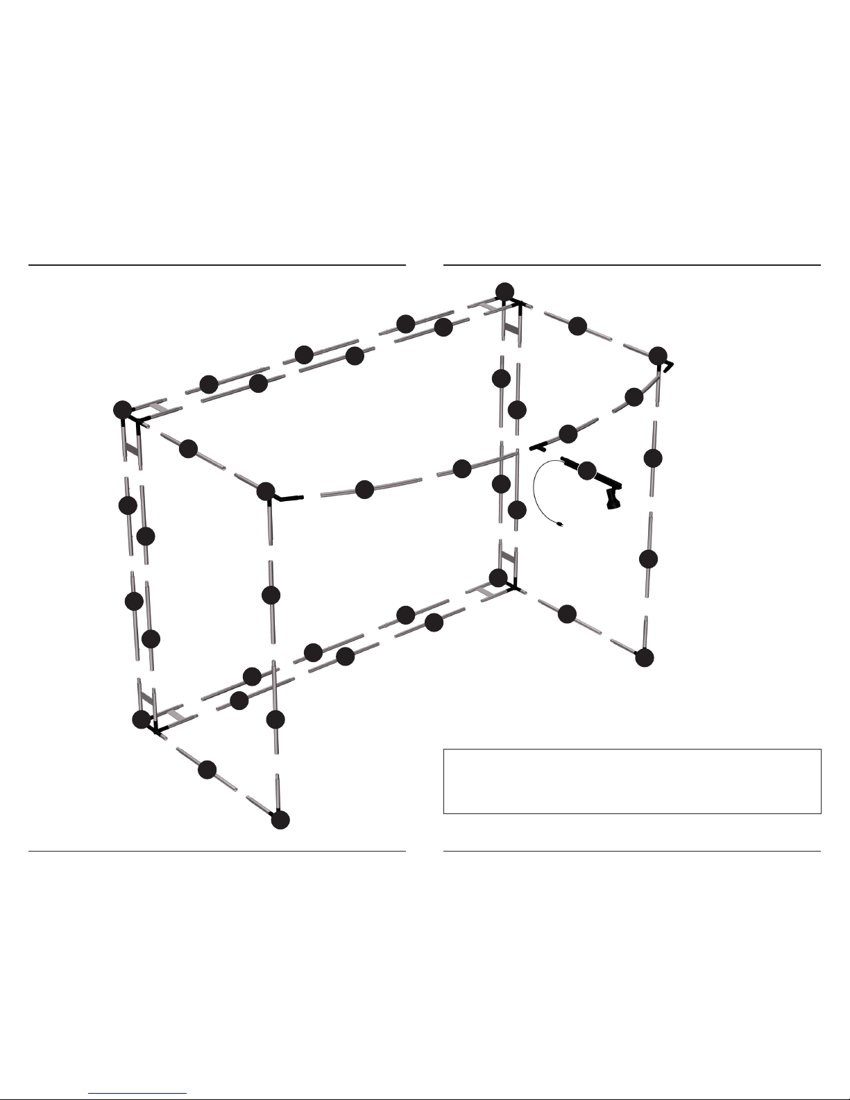
FRAME DIAGRAM
Note: The Vista 12 and Vista 10 frame’s assemble the same
with the exception of several smaller frame pieces on the
Vista 10. These include: 2,5,7,9,12,15,17,19,G,K, & M.
TRUGOLF
4 5
VISTA 10/12
ASSEMBLE FRAME
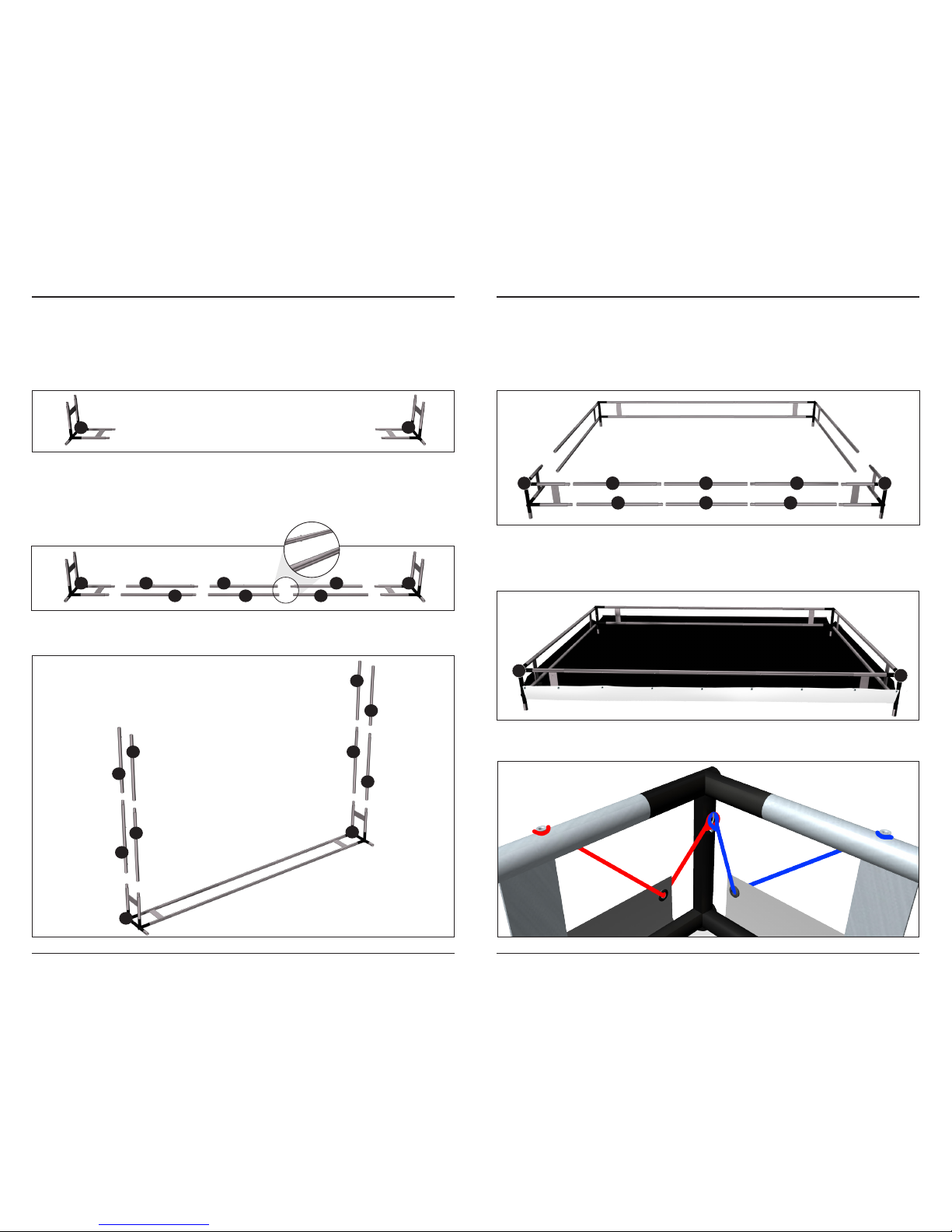
STEP 1 | CORNER PIECES
Start assembling the frame with the back corner pieces labeled [A] & [B].
Place these several feet from the back wall and 10 feet apart.
STEP 2 | CONNECT CORNERS
Connect the frame tubular pieces by sliding the male & female ends together
until the SPRING BUTTON pushes through the hole and locks the pieces
together. Connect corners [A] & [B] together using the pieces shown below.
STEP 3 | ASSEMBLE SIDES
Connect the side frame pieces to the base as shown below.
STEP 4 | TOP CORNER PIECES
Assemble the top portion of the frame. Connect [C] & [D] to the sides, then
insert the top frame pieces between [C] & [D] as shown below.
Tip: To make assembling the frame top easier, tip the frame forward and lay it
on the ground.
STEP 5 | ATTACH THE SCREEN
From within the frame, unfold the SCREEN, black side up. Make sure the
edge labeled TOP is between Corners [C] & [D].
On each corner loop the bungee cord ends over the hooks that are mounted
on frame as shown below.
A 1
11
2
12
3
13
B
B
A
A
B
20
10
14
419
9
15
5
C 8
18
7
17
6
16
D
C
D
TRUGOLF
6 7
VISTA 10/12
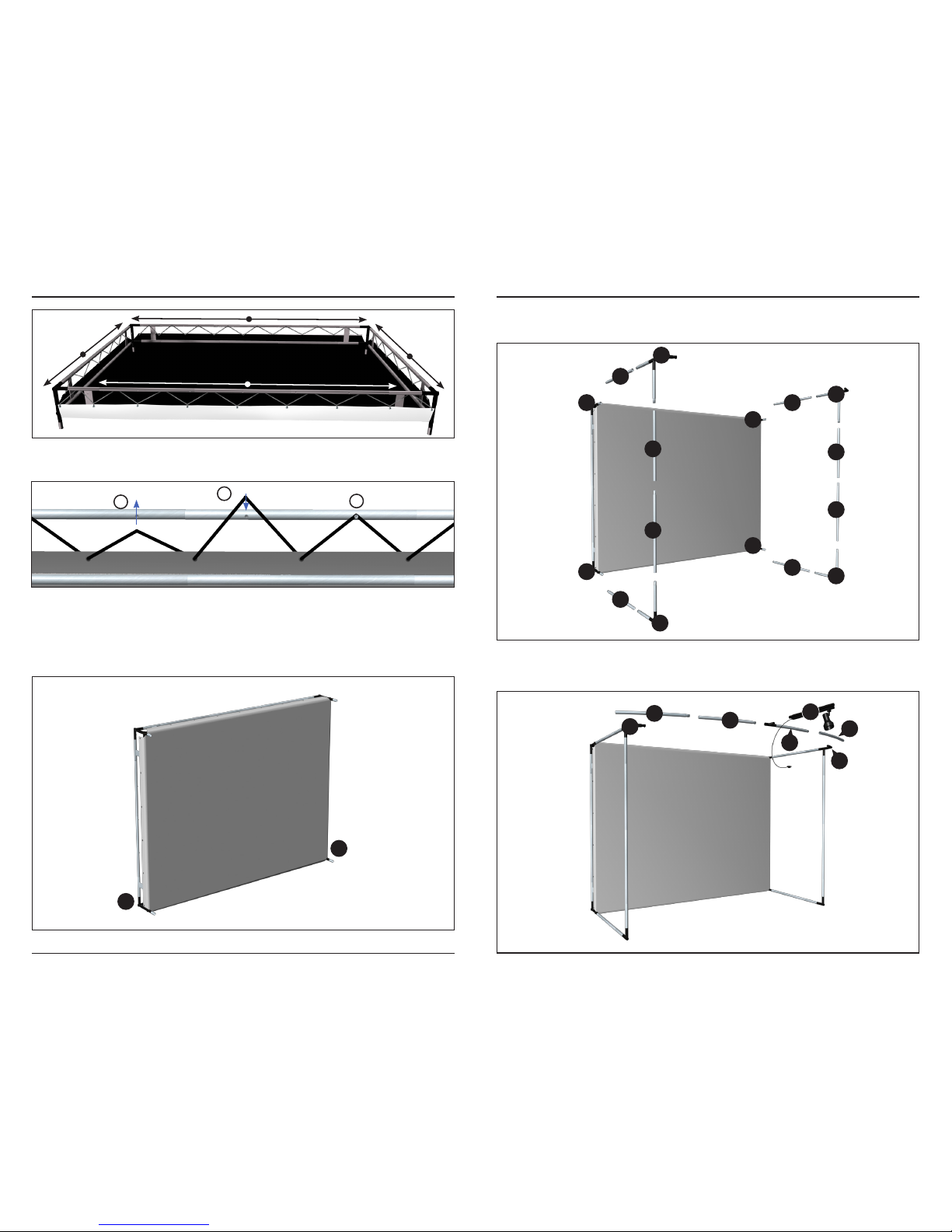
Stretch bungee cord up and onto the INSIDE KNOBS to create a zigzag pattern.
STEP 6 | STAND IT UP
Tip the frame back up so that Corner pieces [A] & [B] are on the bottom.
STEP 7 | SIDES AND TOP
Assemble the walls as shown below.
Next, assemble the FRONT of the frame, start from one side and work your
way to the other. Connect the LIGHT BAR [Q] last. See Overhead Light
Instructions (pg 20) for connecting light.
Attach the remaining bungee cord to the frame. Start from the center
moving out to the corners.
1
3
2
E
I
H
L
A
B
AA
BB
CC
DD
C
D
G
K
F
J
P
O
Q
N
M
DD
CC
A
B
 Loading...