

Visslo F8 premier Operation Manual
OPERATION MANUAL
3D PATTERNLESS LENS EDGER/ F8 premier
Rev. 1014-0912

WWW.VISSLO.COM
#301, Apollo Town, 18-36, Sanbon-Dong, Gunpo-City, Korea Tel+82 31 349 8693 Fax+82 31 349

1. Introduction
1.1 Product outline & Intended use
1.2 Lens materials and edging modes
1.3 Accessary and locking / unlocking procedure
2. System components
2.1 System Layout
2.1.1 Overview
2.1.2 Front View
2.1.3 Rear View
2.2 Main Panel
2.3 Edger key switch
2.3.1 Sub Panel 2 (Right)
2.4 edging unit
3. Edgering data input
3.1 material selection
3.2 Edging data input
3.2.1 Standard lens
3.2.2 Bi-focal lens
4. Edgings
4.1 Standard(Beveling)
4.1.1 Automated edging
4.1.2 Controlled edging ( Decenteriged Edring )
4.2 Optional edging
4.2.1 Classifications by frames
4.2.1.1 Flat (Rimeless) edging
4.2.1.2 Grooving
A) Automated
B) Controlled ( Decenteriged )
4.2.2 Classifications by lens
4.2.2.1 EX lens edging
4.2.3 Edging by the function
4.2.3.1 Frame exchange edging
4.2.3.2 Safe mode lens Edging
4.3 Check and adjust lens size
3D PATTERNLESS LENS EDGER/F8 premier
INDEX

5. Save and retrieve data
5.1 Save and retrieve data
5.1.1 Save data
5.1.2 Retrieve data
5.1.3 Adjust the parameters
6. Installation and maintenance
6,1 Installation
6,2
check
6,3 maintenance
6,4 cleaning
7. Safety
7.1 Caution while use
7.2 Transfer
7.3 Wiring
8. Error codes
9. Usable environmental conditions
10. Symbol Description
1.1 Outline of the Product & Intended use
The lens Edger ( Model:F8 premier ) is edging the optical lens according to the tracing
data which is imported from the tracer unit ( Moder st-88 )
Thelens edger ( Moder:F8 premier ) consists of Edger unit, display and electronic unit.
The lens edger ( Model: F8 premier ) can be equipped with OMA compliances for
laboratory operation
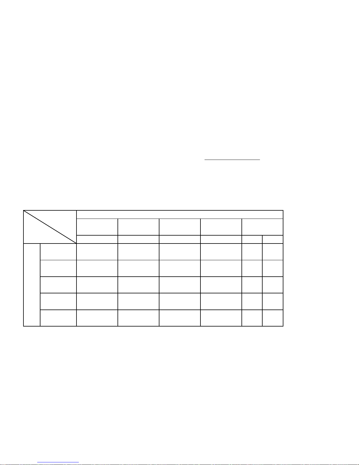
1.2 Lens materials and edging modes
x : Edging is not available
Flat
Bevel
Lens
material
(Acrylic resin)
Edging mode
(Hi-index plastic)
PLA
(Plastic)
HPA
oo
Beveling
o
o
o
PolishingGrooving Flat Chamfering
o
o
o o
PC
(Polycarbonate)
GLS
(glass)
o
o o
o
o
o
o
ACR
o
o
o
o
o
o o
x
o
Chapter 1. Introduction
o
x x
o o
1.3 Accessaries &locking & unlocking procedure
1.3.1 Composition
1) Main body 1 Unit
2) Manual blocker 1 Unit ( Optional )
3) Power cable
4) Leap tape -- 100 pcs for 28mm, 100 pcs for 18mm
5) Operation manual
6) Dressing stick -- #100, #400, #3000 each 1 pc
#100 -- Glass wheel
#400 -- Finishing wheel , Chamfering wheel
#3000 -- Polishing wheel
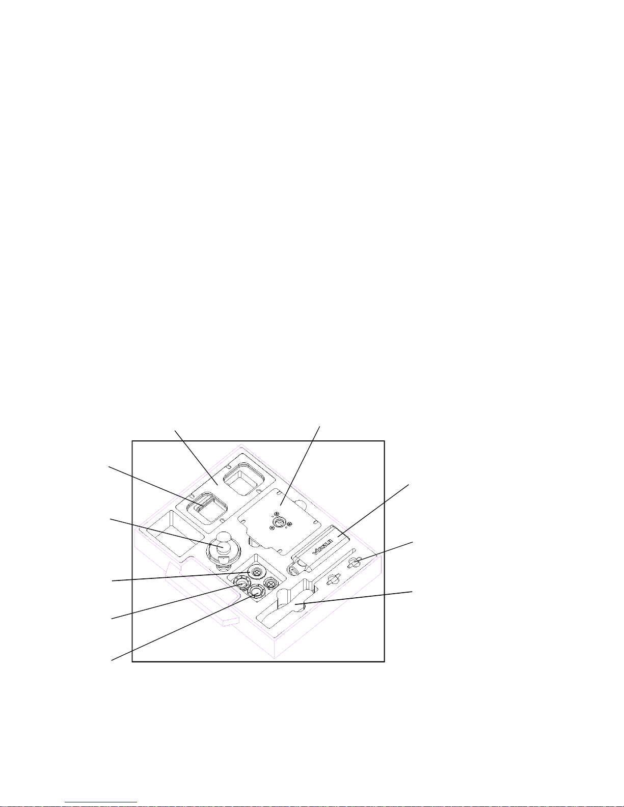
7) Tool Box
8) Pump Unit (Optional)
Tool Box Composition
Frame jig
Wrench set
Calibration jig
Leap cup
Lens adaptor
Lens clamp
Fuse
Leap cup remover
( Block remover )
Pattern & Demo Lens Holder
Wrench driver
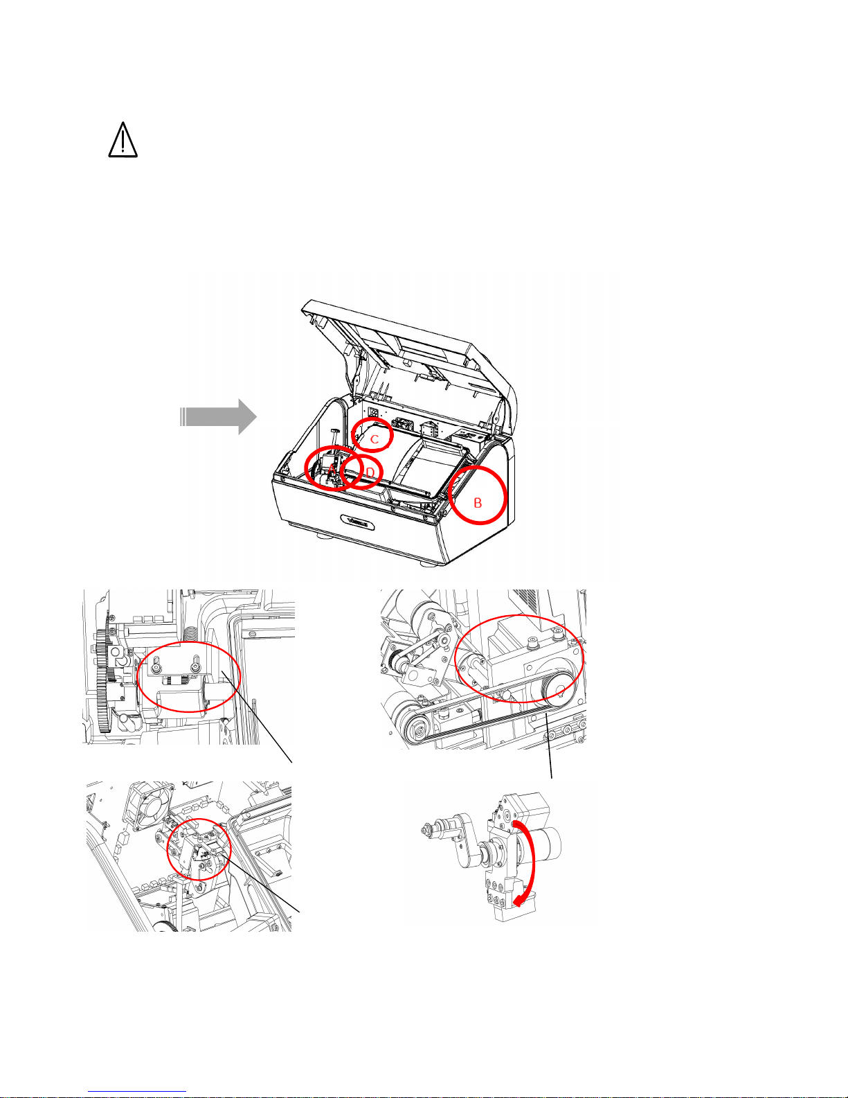
1.3.2 Accessaries and Locking & unlocking procedure
Warning
Be sure to take fixing unit out before turning on certainly since fixing unit are
installed to prevent the damage during transportation
1) Open cover upside after taking the bolts out both sides of the cover upside
fixing unit A
fixing unit Afixing unit A
fixing unit A~~~~DDDD
red-colored
red-coloredred-colored
red-colored
red-colored
Head Up
Head UpHead Up
Head Up////Down Locking A
Down Locking ADown Locking A
Down Locking A
red-colored
Head L
Head LHead L
Head L----R Locking B
R Locking BR Locking B
R Locking B
Edger fixing unit location
Edger fixing unit locationEdger fixing unit location
Edger fixing unit location
Feeler Locking C
Feeler Locking CFeeler Locking C
Feeler Locking C
Groove Locking
Groove LockingGroove Locking
Groove Locking DDDD
fixing with
fixing with fixing with
fixing with
adhesive tape
adhesive tapeadhesive tape
adhesive tape
*chock any interference with movement
*chock any interference with movement*chock any interference with movement
*chock any interference with movement
Locking units should always removed with turn off condition.
Locking units should always removed with turn off condition.Locking units should always removed with turn off condition.
Locking units should always removed with turn off condition.
locking units should always be placed when the transportation is necessary.
locking units should always be placed when the transportation is necessary.locking units should always be placed when the transportation is necessary.
locking units should always be placed when the transportation is necessary.
improper handling could cause the damage which is not covered underwarrenty.
improper handling could cause the damage which is not covered underwarrenty.improper handling could cause the damage which is not covered underwarrenty.
improper handling could cause the damage which is not covered underwarrenty.
3)Edger fixing lockerA ,B, C, D is limited.
3)Edger fixing lockerA ,B, C, D is limited.3)Edger fixing lockerA ,B, C, D is limited.
3)Edger fixing lockerA ,B, C, D is limited.
2.1 System Layout
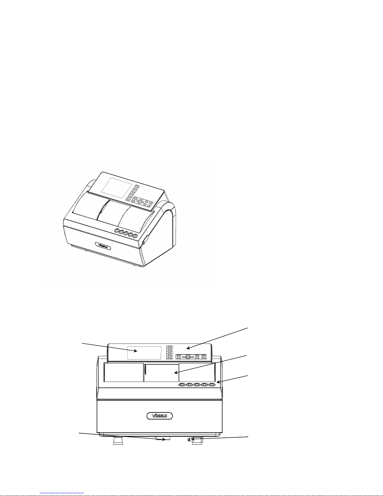
2.1.1 System Overview
Fig. 1
2.1.2 Front view
Chapter 2. System components
WxLxH (Approx.) : 800 x 430 x 410 (mm)
Control
ControlControl
Control Panel
PanelPanel
Panel
Sliding Cover
Sliding CoverSliding Cover
Sliding Cover
Edger Key Switch
Edger Key SwitchEdger Key Switch
Edger Key Switch
Water Drain Port
Water Drain PortWater Drain Port
Water Drain Port
Water Inlet Port
Water Inlet PortWater Inlet Port
Water Inlet Port
LCD Display
LCD DisplayLCD Display
LCD Display
* Control Panel : Shows and control all menu
* Edger Key switch : Controls conditions before edging
* Sliding Cover : Shields the noise and filthy water while edging
* Water Inlet Port : Outside nozzle to deliver water while edging
* Water Drain Port : Outlet to release water after edging
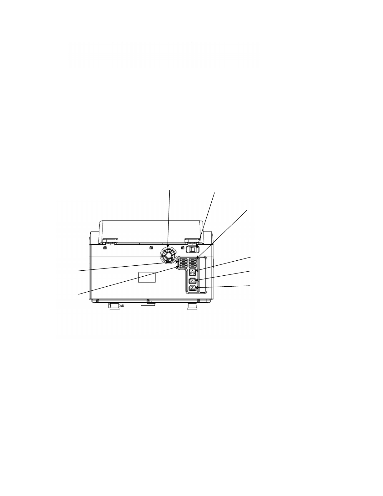
2.1.3 Rear view
Fig. 3
* RS-232C Connector : Connector to interface with equipment outside.
* Barcode Scanner Connector : Connector to interface with bar code scanner
Cooling Fan
Cooling FanCooling Fan
Cooling Fan
RS
RSRS
RS----232
232232
232C
C C
C
Interface Connector
Interface ConnectorInterface Connector
Interface Connector
Barcode
BarcodeBarcode
Barcode
Scanner Connector
Scanner ConnectorScanner Connector
Scanner Connector
Pump
PumpPump
Pump1
1 1
1 Connector
ConnectorConnector
Connector
Power Switch
Power SwitchPower Switch
Power Switch
Power Connector
Power ConnectorPower Connector
Power Connector
Blocker
BlockerBlocker
Blocker
Connector
ConnectorConnector
Connector
Tracer
TracerTracer
Tracer
Connector
ConnectorConnector
Connector
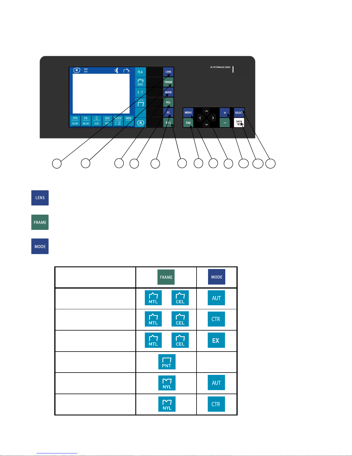
2.2 Control Panel
Fig. 4
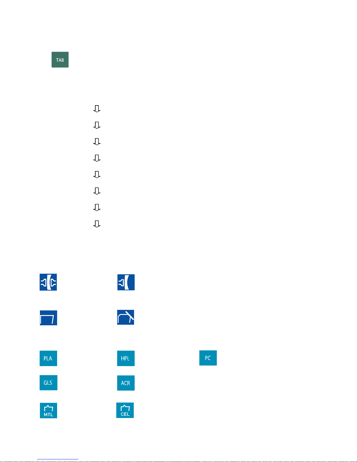
1. : Lens material --- Choose PLA(Plastic), HPL(High index plastic),
PC(Polycarbonate),GLS(Glass),or ACR(Acrylic resin)
2. : Frame material --- Choose MTL(Metal), CEL(Celluloid)/ZYL, PNT(two-point),
or NYL(Nylor)
3. : Edging mode - 3:7(Auto), 4:6(Auto), 5:5(Auto), CTR(Manual),
EX(EX lens ) are available.
EX lens edging
Controlled grooving
Automated grooving
Rimless(Flat)edging
Edging mode
Controlled beveling
Automated beveling
12114
6 7 8
9
10
2
51
3
4. : Use when choose rimless polishing mode.
{(This key is not working in Type GLS(Glass)}
5. : Use when choose frame switching mode.
6. : Use when choose the sides of lens or right(R) or left(L)
7. : Use when choose in setting up the steps of the figures if change edging data.
8. : Use when choose specific menu.
9. : Use when move cursors
10. : Use when regulate the increments and decrements of edging data
11. : Use when transmit the traced data to screen panel.
12. : Use when change input shape of designed data
13 15 16 17
18
19
20
22
26 27
28
MIN : 70.00
V(Vertical)
H(Horizontal)
14
23
24
25
21
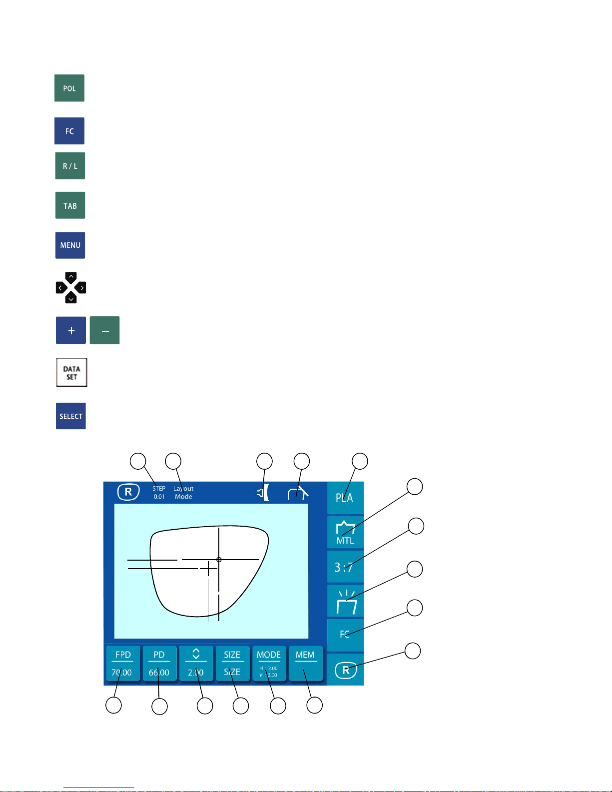
13. Indicate changed volume of the figures to enter
Use key and shows by 0.01, 0.1, 0.5(mm)
14. Indicate process steps
Layout Mode : steps to enter edging conditions
Measure process : steps to measure the thickness of lens
Controlled edging ,EX lens edging: Controlled edging,EX lens edging
Rough process : steps to edger roughing wheel
Bevel process : steps to bevel
Finish process : steps to edge delicate
Polish process : steps to polish
Groove process : steps to groove
Chamfer process : steps to chamfer
15. Shows the clamp is locked or not.
: chuck : unchuck
16. Shows chamfered or not
: no chamferring :Chamferring
17. Lens materials
: Plastic : High index plastic : Polycarbonate
*Front or Rear
*Both
: Glass : Acrylic resin
18. Frame materials
: Metal : Celluloid

: Nylon : two-point (drilled)
19. Edging mode
: Auto mode : Controlled mode : EX lens mode
* (Blank) indicates the flat edging without grooving.
20. Shows polishing mode.
: Polishing : No polishing
21. Frame changing mode
: Frame changing mode
22. the selected side of a lens to be edged(R/L)
: Right : Left
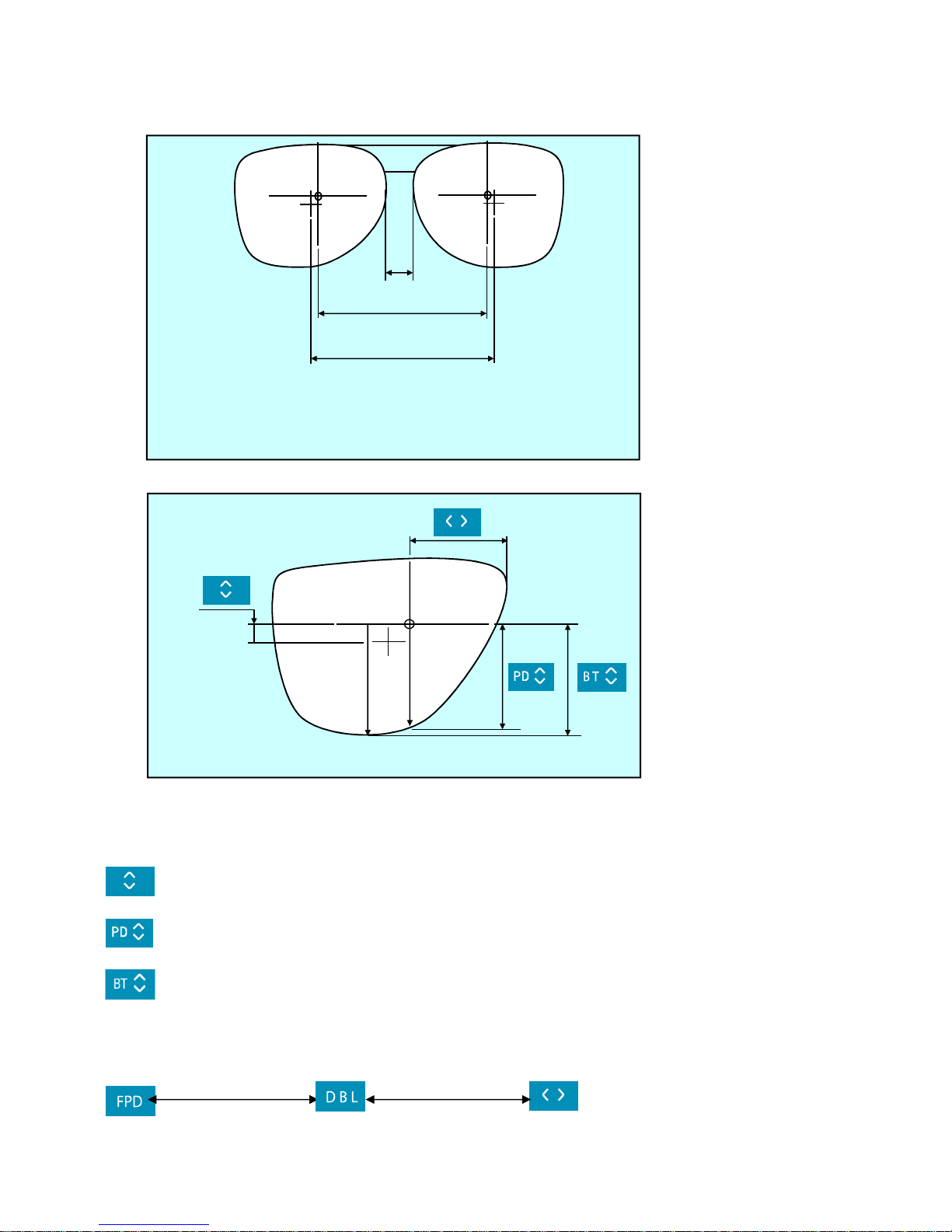
23. Optical center
Fig. 6
fig.6
Fig. 7
: Distance between rim center and optical center by the steps of 0.1mm
: Crossing distance from optical center to lens vertically
: Crossing distance from optical center to the bottom of lens vertically
24. FPD (Frame pupil distance) - Pupil distance of glasses frame
DBL (Distance between nasal points) - Distance between nasal points and frame.
(Fig.6,7)
DBLLLL
PD
FPD
25. PD (Pupillary distance)
(30.00mm~99.50mm by the steps of 0.5mm)
26. SIZE (Size compensation value)
Indicates the compensation value for the complete lens size required from
diameter,which is originated from traced size of the frames or patterns(0.00)
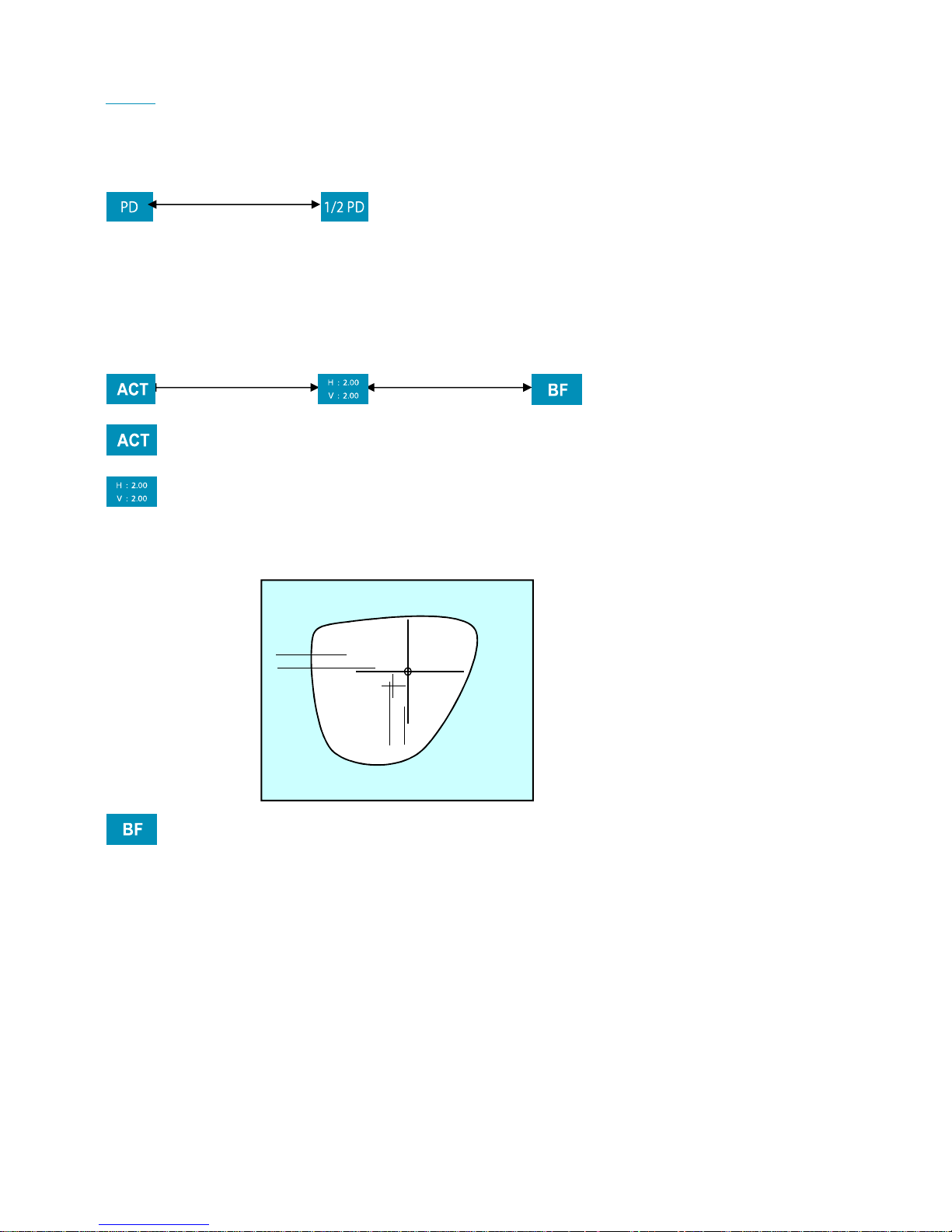
27. Layout mode
: (Optical center)
: (Frame center)
Indicate horizontal and vertical distance between optical center and
frame center
: Bi-focal lens mode
27. Memory address(MEM)
Store or read the traced pattern data while use memory function and may be able
to store up to 120 addresses.
MIN : 70.00
V(Vertical)
H(Horizontal)
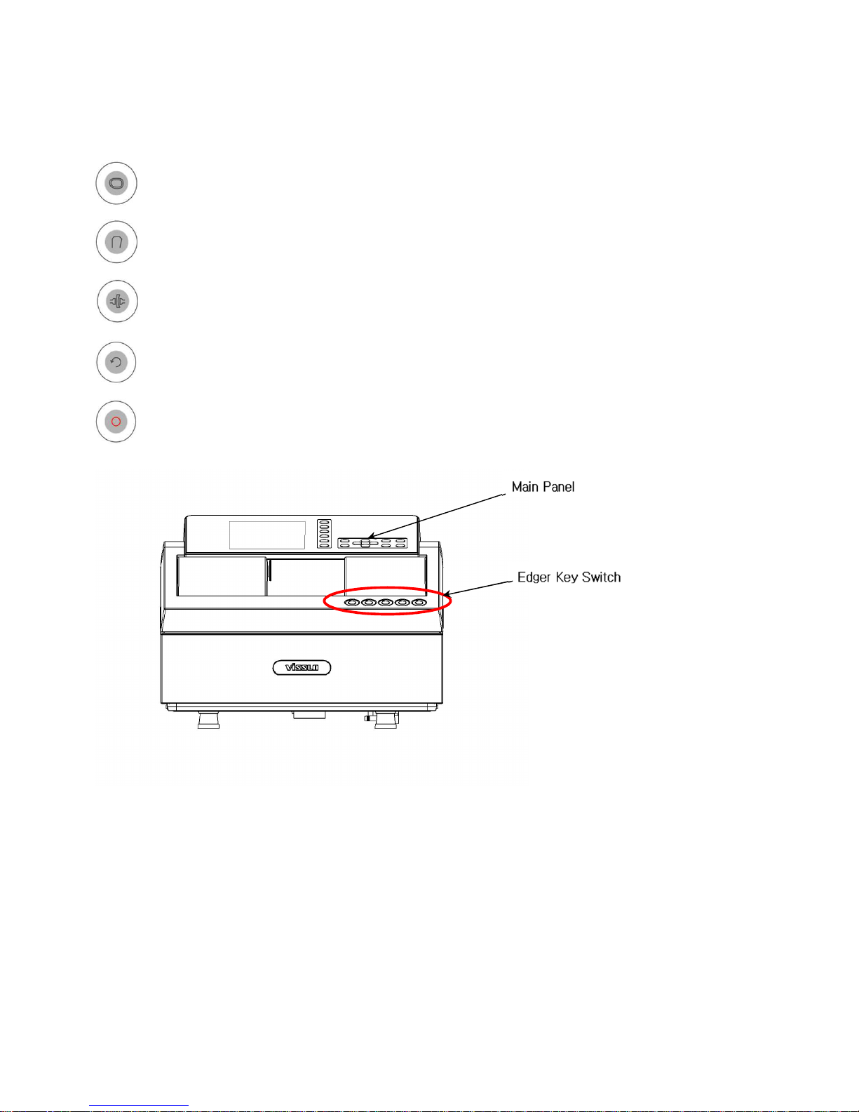
2.3 Edger key Switch
2.3.1 Menu
: Retouch -- minor adjusting
: Safety Bevel -- chamferring mode on/off
: CHUCK
: START -- Start Edging
: STOP -- Stop Edging
 Loading...