

VISSEM Electronics Opticube VSOF-OTB-E User Manual
OPTICAL TERMINATION BOX
removing point on the cable
0cm point from
VSOF-OTB-E Manual
Component List
Items Unit
Protection Tube EA 2 X Splice Tray
Heat shrinkable sleeve EA Number of cores
Key Lock EA 2
Cable tie EA 4 X Splice Tray
Cord Protection Tube EA 4 X Splice Tray
Q’ty
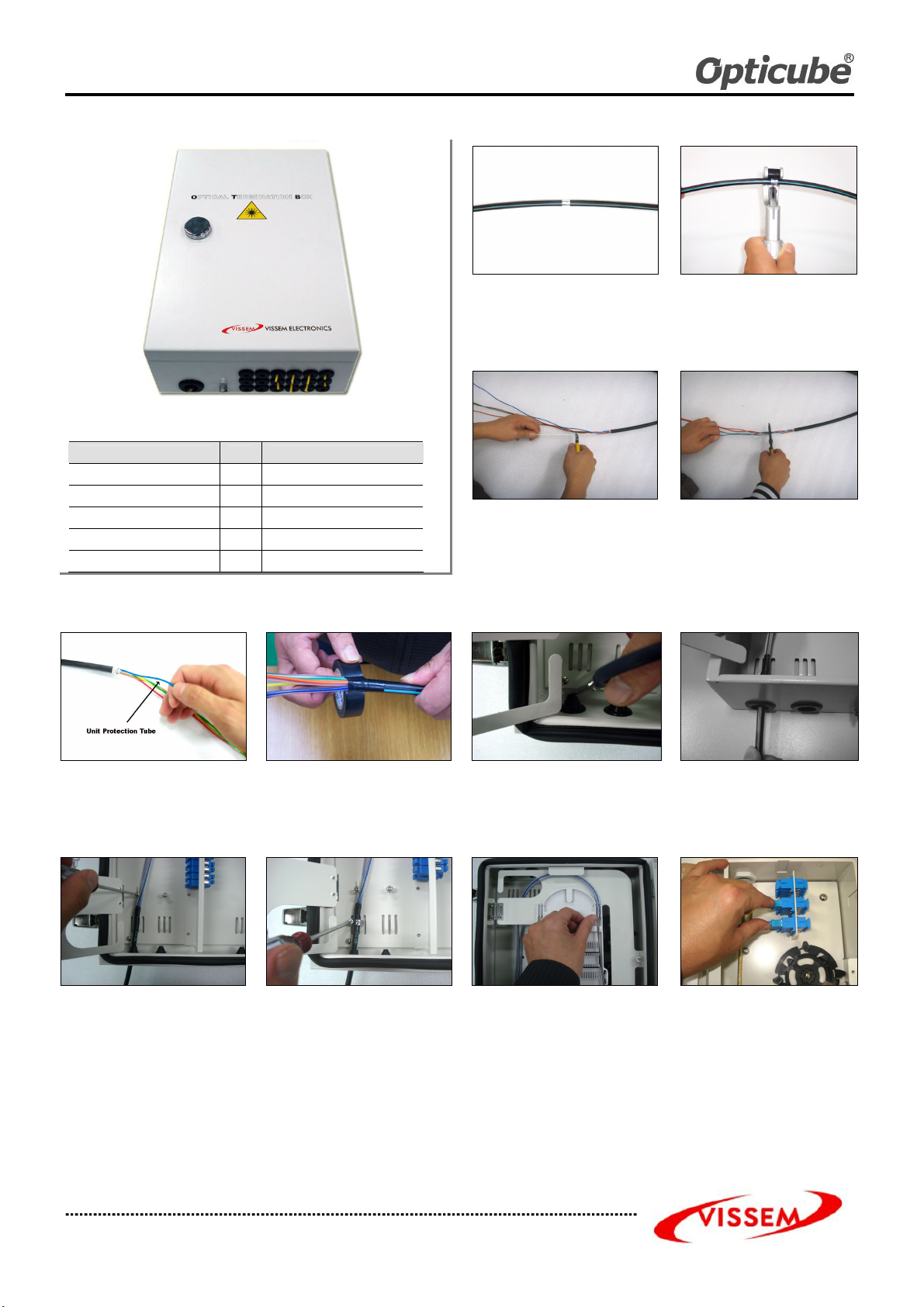
1. Marking a Cutting Point
Mark a sheath
with a piece of tape at a 10
the cable cut end.
3. Cutting Tension Member
Leave 6cm from the cable and cut off the
tension member.
2. Sheath Removing
Remove the cable sheath from the
marked point by using a sheath stripper
Remove all plastic tape.
4. Removing Loose Tubes
Leave about 4cm from the cable sheath
end and remove the rest of the loose
tube.
Clean the cut area by using jelly cleaner.
Note. Be sure not to damage the fiber
optics.
5. Inserting Unit Protection Tube
Insert fibers into the unit protection tubes
carefully all the way up to the point where
loose tubes end.
8. Fixing Fiber Optic Cable
Insert the tension member into the T/M
fixing bracket and tighten them together
by using a screwdriver
VISSEM OTB-E Manual Rev.0 TEL: 82-31-283-7852 FAX: 82-31-283-7844
All rights reserved by VISSEM Electronics Co. Ltd.
Wrap the tape around the end point of
protection tube at cable side.
Secure the cable to the center of the
Susband Bracket by using a susband
6. Cutting Sheath Gasket
Check the outer diameter of the cable and
cut off the sheath gasket according to the
cable diameter marked on it.
9. Routing Protection Tube
Route protection tubes to the splice tray
inlet and secure the protection tubes on
the splice tray inlet by using cable tie.
7. Inserting Fiber Optic Cable
Check the outer diameter of the cable
and cut off the sheath gasket according
to the cable diameter marked on it.
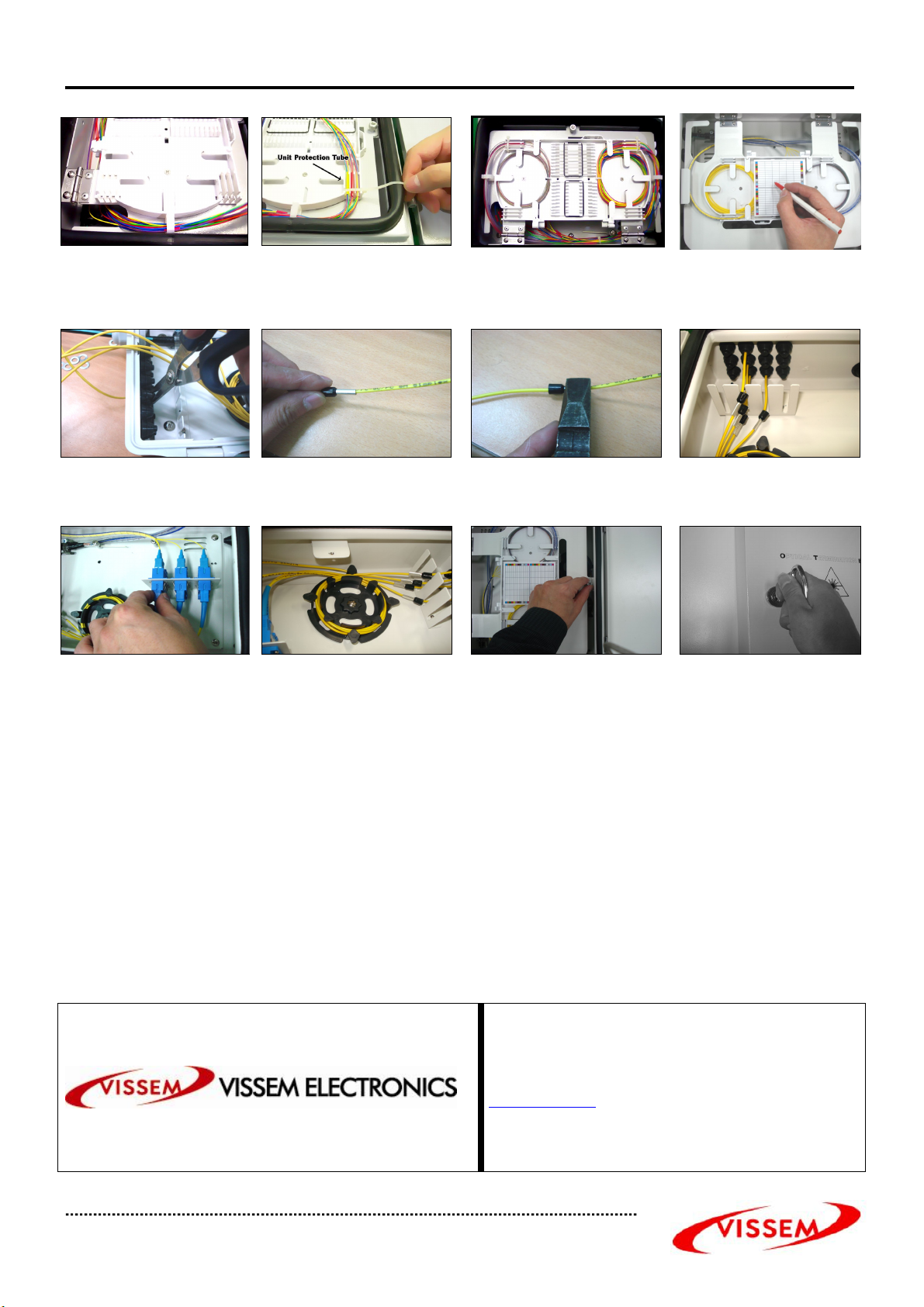
10. Pigtail Connection
Connect the pigtails to the adapters by
turns on the adapter panel.
Optical Termination Box (VSOF-OTB-E) User Manual (Rev.0)
to the adapters on
the splice tray supporter and fasten it
11. Routing Pigtail
Route cord and guide them into stacked
Splice tray
14. Cutting Drop Cable Gasket
Cutting Drop Cable Gasket and Inserting
Drop Cable
16. Drop Cable Connection
Connect the drop Cable
the opposite side e
Insert cord into splice tray inlet and tie
Together by suing cable ties
15. Inserting aramid yarn gripper
Fold th4e aramid yarn and put it in the
aramid yarn gripper
17. Routing Drop Cable
Arrange the cords on the spool
12. Splicing
Splice fibers in accordance with
splicing method to be approved
Press the steel part of aramid yarn gripper
with plier
16. Finishing the Termination Box
Close
by using a captive screw bolt.
13. Recording
Splice fibers in accordance with
splicing method to be approved
Combine drop cable gasket and aramid
yarn gripper
Push the door back to the shelf and lock
them by using a key to be provided
The OPTICUBE has been made under strict quality control and tests. Our products passed several inspection criteria, specifications and other
certification standards.
The technical facts of the products are based upon reliable information, but the user should c onsider the usage and applicability of the product
before operation. Sellers do not assume any liability resulting from improper use. The contents of this manual are made in lieu of all warranties,
but sellers do not take the responsibility for any damage caused by users or any statements unrelated to this manual.
VISSEM Electronics
235-2, Deokpyeong-ri, Majang-myeon, Icheon-city,
Gyeonggi-do, Korea 467-812
www.opticube.co.kr
Email: opticube@vissem.com
Tel: 82-31-283-7852 Fax: 82-31-283-7844
ãVISSEM OPT-M0711 Printed in Korea
VISSEM OTB-E Manual Rev.0 TEL: 82-31-283-7852 FAX: 82-31-283-7844
All rights reserved by VISSEM Electronics Co. Ltd.
 Loading...