

Visonik VMX-150D, VMX-300D, VMX-450D Installation Instructions Manual
DE9980 1
VMX-150D / 300D / 450D
2-Beam Infrared Detectors
Installation Instructions
1111. FEATURES
. FEATURES. FEATURES
. FEATURES
• State-of-the-art circuit
• Durable housing
• Dual photoelectric beam sensor
• Minimum false alarms
• Indoor and outdoor use
• Excellent immunity to freezing, snow, rain, fog, and other
bad weather conditions
• Anti-frost design
• N.C. tamper switch included
Note: The VMX-150D / 300D / 450D are designed to detect
movement of an intruder. However, note that environmental
disturbances in the protected area may also cause the sensor to
create an alarm. Test the detector periodically for continuous
satisfactory operation before arming the alarm system.
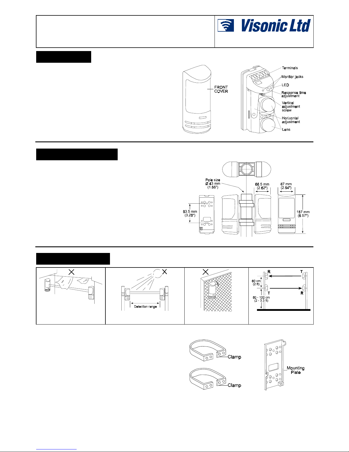
Figure 1. General View
Figure 2. Inside View
2222. SPECIFICATIONS
. SPECIFICATIONS. SPECIFICATIONS
. SPECIFICATIONS
Outdoor Usable Distance:
25 / 50 / 75 m (82 / 164 / 246 ft)
Indoor Usable Distance:
50 / 100 / 150 m (164 / 328 / 492 ft)
Beam:
Infrared photoelectric, 1 kHz, 940 nm infrared pulse
Interrupt Time
: Adjustable from 50 ms to 500 ms.
Power Input
: 10 to 24 VDC
Current (mA):
55 (VMX-150D) / 60 (VMX-300D) / 65 (VMX-450D)
Alarm Output:
N.C., 30 VDC, 1 A max., 1 s
Transmitter LED:
Green (indicates transmit)
Receiver LEDs:
Red (indicates alarm) and green (indicates standby)
Align Angle:
± 5° vertical. ± 90° horizontal
Temperature:
-25 to 60°C (-13 to 140°F)
Mounting:
Wall or pole (pole clamps and screws included)
Size:
67 X 167 X 66.5 mm (2.64 X 6.57 X 2.62 in.)
Wire Connection:
Screw-type terminals
Case:
PC, ABS plastic, waterproof
Tamper:
N.C., becomes N.O. when cover is removed
Figure 3. Dimensions
3333. INSTALLATION
. INSTALLATION. INSTALLATION
. INSTALLATION
Avoid blocking objects
Avoid direct sunlight and keep the
max. detecting range as prescribed
Do not mount unit on unsecure or non-solid surface
When installing several units,
mount as shown above
3.1 Mounting
A. Wall Installation
( 1 )
Loosen the cover locking screw and remove the cover. Loosen
the unit setting screw at the lower part of the unit. Slide the
mounting plate downwards and remove it.
( 2 )
Feed the wires through the wiring holes of the mounting plate
before fixing the plate to the wall.
( 3 )
Fix the mounting plate firmly on the wall with the mounting
screws supplied.
B. Pole Installation
( 1 )
Use a 43 mm (1.66”) mounting pole
( 2 )
Fix the clamps onto mounting plate with supplied screws. Place
the clamps around the pole and tighten firmly with the pole
locking screws.
( 3 )
Feed the wires through the wiring hole of the mounting plate
.
Figure 4. Pole Clamps
Figure 5. Mounting Plate
2 DE9980
3.2 Wiring
(transmitter and receiver)
• (+):
Connect to the (+) output of a 10 to 24 VDC power source.
• (–):
Connect to (–) output of a 10 to 24 VDC power source.
• TAMPER:
Connect to the N.C. tamper circuit of the control panel.
• ALARM (receiver only):
Connect to N.C. burglar zone input.
NOTE: Grounding may be necessary, depending on the location
.
3.3 Alignment
A . Eyeball - make horizontal / vertical alignments visually:
•
Look into one of the transmitter's viewfinders (one of the four
holes located between the two lenses) at a 45° angle.
•
Adjust the lens horizontally by turning it left and right by hand until
the receiver is clearly seen in the viewfinder.
•
Use a screwdriver to turn the vertical adjustment screw (above the
lens on the lens bracket) clockwise or counterclockwise until the
receiver is clearly seen in the viewfinder.
•
Repeat the same steps for the receiver
.
Note: If you cannot see the opposite unit in the viewfinder, put a
sheet of white paper near the unit to be seen. Move your eyes
about 5 cm away from the viewfinder and try again.
B . Meter - fine tune the receiver's adjustment:
•
Set the range of a volt-ohm meter (VOM) to 0-9 VDC.
•
Insert the red (+) probe into the (+) terminal and the black (–)
probe into the (–) terminal. Measure the voltage.
•
Adjust the horizontal angle by hand until the VOM indicates the
highest voltage.
•
Adjust the vertical angle by turning the vertical adjustment screw
until the VOM indicates the highest voltage.
•
Do not interrupt the beam while adjusting. 2.7 VDC is the
maximum possible reading. Anything over 2.0 VDC is good, and
over 1.5 VDC is acceptable. The higher the reading, the better. In
misty areas, the
reading must be over 2.0 VDC.
3.4 Testing the system
•
Power up the transmitter and receiver. If the LED remains steadily
ON even when the beam is not interrupted, realign the units.
•
Walk between the transmitter and receiver at various speeds to
interrupt the beams. Adjust the delay time control as needed.
•
Detection will occur only if both the upper and lower beams are
simultaneously interrupted.
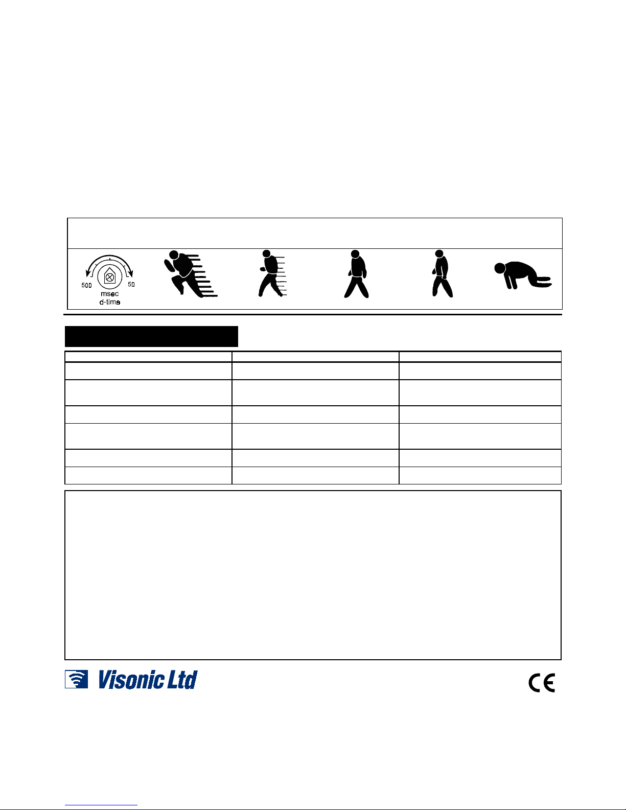
• The beam interrupt control determines how long the beam can be interrupted before triggering the alarm.
• Adjust the beam interrupt control as required at the specific site. You may need to make adjustments later after completing the walk test.
•
The following figures show the typical values for sensing an adult.
Fast running (50 ms)
Jogging (100 ms)
Fast walk (200 ms)
Normal walk (350 ms) Slow motion (500 ms)
4444. TROUBLESHOOTING
. TROUBLESHOOTING. TROUBLESHOOTING
. TROUBLESHOOTING
TROUBLE CHECK REMEDY
Transmitter LED does not light Incorrectly wired and/or insufficient voltage Ensure the power supply to the transmitter is
10 to 24 VDC
Receiver LED never lights up when the beam
is interrupted
Insufficient voltage
Beam reflected away from receiver
Beams not simultaneously interrupted
Raise voltage
Clean the cover
Check overall installation
Beams interrupted and LED lights, but no
alarm is triggered
Alarm trigger cable may be cut, or relay
contacts stuck due to overloading
Check wiring and the effect of the load on the
output level or overhaul the unit
Alarm LED continuously illuminated Lenses out of alignment
Beams are blocked
Cover is foggy or dirty
Realign the lenses
Remove any obstacles
Clean the cover
Alarm trigger becomes erratic in bad weather Lenses out of alignment Check overall system installation. If still
erratic, realign the lenses
Frequent false alarms triggered by leaves,
birds, etc
Too sensitive
Bad location
Reduce beam interrupt speed
Change location
WARRANTY
WARRANTYWARRANTY
WARRANTY
Visonic Ltd. and/or its subsidiaries and its affiliates ("the Manufacturer") warrants its
products hereinafter referred to as "the Product" or "Products" to be in conformance with
its own plans and specifications and to be free of defects in materials and workmanship
under normal use and service for a period of twelve months from the date of shipment by
the Manufacturer. The Manufacturer's obligations shall be limited within the warranty
period, at its option, to repair or replace the product or any part thereof. The Manufacturer
shall not be responsible for dismantling and/or reinstallation charges. To exercise the
warranty the product must be returned to the Manufacturer freight prepaid and insured.
This warranty does not apply in the following cases: improper installation, misuse,
failure to follow installation and operating instructions, alteration, abuse, accident or
tampering, and repair by anyone other than the Manufacturer.
This warranty is exclusive and expressly in lieu of all other warranties, obligations or
liabilities, whether written, oral, express or implied, including any warranty of
merchantability or fitness for a particular purpose, or otherwise. In no case shall the
Manufacturer be liable to anyone for any consequential or incidental damages for breach
of this warranty or any other warranties whatsoever, as aforesaid.
This warranty shall not be modified, varied or extended, and the Manufacturer does not
authorize any person to act on its behalf in the modification, variation or extension of this
warranty. This warranty shall apply to the Product only. All products, accessories or
attachments of others used in conjunction with the Product, including batteries, shall be
covered solely by their own warranty, if any. The Manufacturer shall not be liable for any
damage or loss whatsoever, whether directly, indirectly, incidentally, consequentially or
otherwise, caused by the malfunction of the Product due to products, accessories, or
attachments of others, including batteries, used in conjunction with the Products.
The Manufacturer does not represent that its Product may not be compromised and/or
circumvented, or that the Product will prevent any death, personal and/or bodily injury
and/or damage to property resulting from burglary, robbery, fire or otherwise, or that the
Product will in all cases provide adequate warning or protection. User understands that a
properly installed and maintained alarm may only reduce the risk of events such as
burglary, robbery, and fire without warning, but it is not insurance or a guarantee that such
will not occur or that there will be no death, personal damage and/or damage to property
as a result.
The Manufacturer shall have no liability for any death, personal and/or bodily injury
and/or damage to property or other loss whether direct, indirect, incidental,
consequential or otherwise, based on a claim that the Product failed to function.
However, if the Manufacturer is held liable, whether directly or indirectly, for any loss or
damage arising under this limited warranty or otherwise, regardless of cause or origin, the
Manufacturer's maximum liability shall not in any case exceed the purchase price of the
Product, which shall be fixed as liquidated damages and not as a penalty, and shall be the
complete and exclusive remedy against the Manufacturer.
Warning: The user should follow the installation and operation instructions and among
other things test the Product and the whole system at least once a week. For various
reasons, including, but not limited to, changes in environmental conditions, electric or
electronic disruptions and tampering, the Product may not perform as expected. The user
is advised to take all necessary precautions for his /her safety and the protection of
his/her property.
6/91
VISONIC LTD (ISRAEL): P.O.B 22020 TEL-AVIV 61220 ISRAEL. PHONE: (972-3) 645-6789, FAX: (972-3) 645-6788
VISONIC INC. (U.S.A.): 10 NORTHWOOD DRIVE, BLOOMFIELD CT. 06002-1911. PHONE: (860) 243-0833, (800) 223-0020 FAX: (860) 242-8094
VISONIC LTD. (UK): UNIT 1, STRATTON PARK, DUNTON LANE, BIGGLESWADE, BEDS. SG18 8QS. PHONE: (01767) 600857 FAX: (01767) 601098
INTERNET: WWW.VISONIC.COM
VISONIC LTD. 2000 VMX-150D / 300D / 450D DE9980- (REV. 0, 4/00)
Made in Korea
for Visonic Ltd.
 Loading...