

Visonik V3209, V3409, V3309, V3509, V3909 Instruction Manual
...
RMS
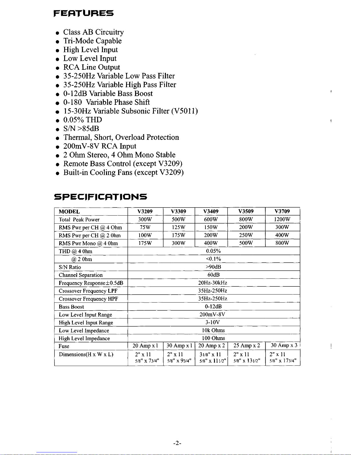
Pwr per CH @ 4 Ohm
RMS
Pwr per CH
@
2
Ohm
RMS
Pwr Mono @ 4 Ohm
THD
@
4 Ohm
SM
Ratio
Channel Separation
Frequency Response+OSdB
Crossover Frequency LPF
Crossover Frequency HPF
@ 2 Ohm
0
Class AB Circuitry
Tri-Mode Capable
0
High Level Input
0
Low Level Input
0
RCA Line Output
0
35-250Hz Variable Low Pass Filter
0
35-250Hz Variable High Pass Filter
0
0-12dB Variable Bass Boost
0-180
Variable Phase Shift
15-30Hz Variable Subsonic Filter (V5011)
0
0.05%THD
0
S/N>85dB
0
Thermal, Short, Overload Protection
0
2OOmV-8V RCA Input
0
2 Ohm Stereo, 4 Ohm Mono Stable
0
Remote Bass Control (except V3209)
0
Built-in Cooling Fans (except V3209)
75W 125W
150W
200w 300W
IOOW 175w
200w 250W
400W
175w 300W
400W 500W 800W
0.05%
<O.l%
>90dB
60dB
20Hz-30kHz
35Hz-250Hz
35Hz-250Hz
MODEL
I
V3209
1
V3309
I
V3409
I
V3509
1
V3709
Total Peak Power
I
300W
I
500W
I
600W
1
8OOW
I
1200w
Bass Boost
Low Level Input Range
High Level Input Range
0-12dB
200mV-8V
3-1OV
Low Level Impedance
High Level Impedance
Fuse
Dimensions(H x W
x
L)
10k Ohms
100
Ohms
20Ampxl 30Ampxl 20Ampx2 25Ampx2 30Anipx3
1
518"
x
7314"
518"
x
9314"
518"
x
11
112" 518"
x
131/2"
518"
x 17314"
2"x11 2"x11 3118"Xll 2"x11
2"
x
11
-2-

MODEL
'
V3909
'
V4309
Total Peak Power
,16oow/1ooo\v
1
RMSPwrperCH@4Ohm
300W
I
500W
1
RMSPwrperCH@2Ohm
1
400W
~
700W
1
RMSPwrMono@4OhniI
I
800W
'
1300W
V5011 V6611
___j
I
lOOOW 2 x 200w
+
1
x
soow
'
300W
1
4x75W+2x 175W
~
N-A
1
4x lOOW+2x25OW
SOOW 2~150W+1x4OOW
1
Fuse
Dimensions(H
x
W x L)
1
40Anipx3 ~ 25 Ampx2
12"x
11
518
X21112"
518"X
15112"
i
2'':
40Ampx
1
20 Amp x
3
I
I
2"x
11
2"
I
1~18"
2
I
112"
1
I
518"X
13112''
~
CONNECTIONS
Each input and output jack is individually labeled to reduce installation
errors. Male to male RCA cables are required to connect the AMPLIFIER
inputs to the source units or crossover outputs. High Quality shielded cables
should be used to minimize the pickup of electrical noises. The RCA cables
should be run on the opposite side
of
the vehicle from the power and ground
wires
of
the Amplifiers. This will help to minimize noise problems.
Before making any electrical connections, Disconnect
your
car battery's
Ground cable to prevent the possibility of short circuits
or
damage to your
electronic equipment.
-3-

0 0 0
I)EMarE
E
6'
4-
CONTROLS
1.
2.
3.
4.
5.
6.
7.
8.
9.
10.
11.
12.
13.
14.
15.
16.
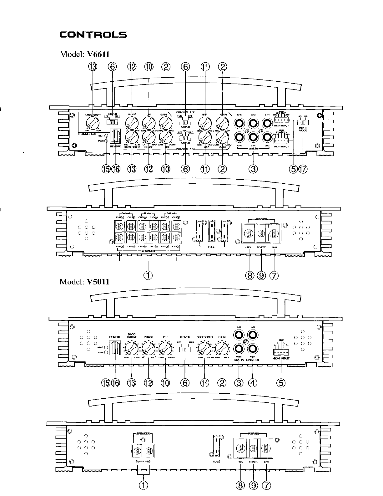
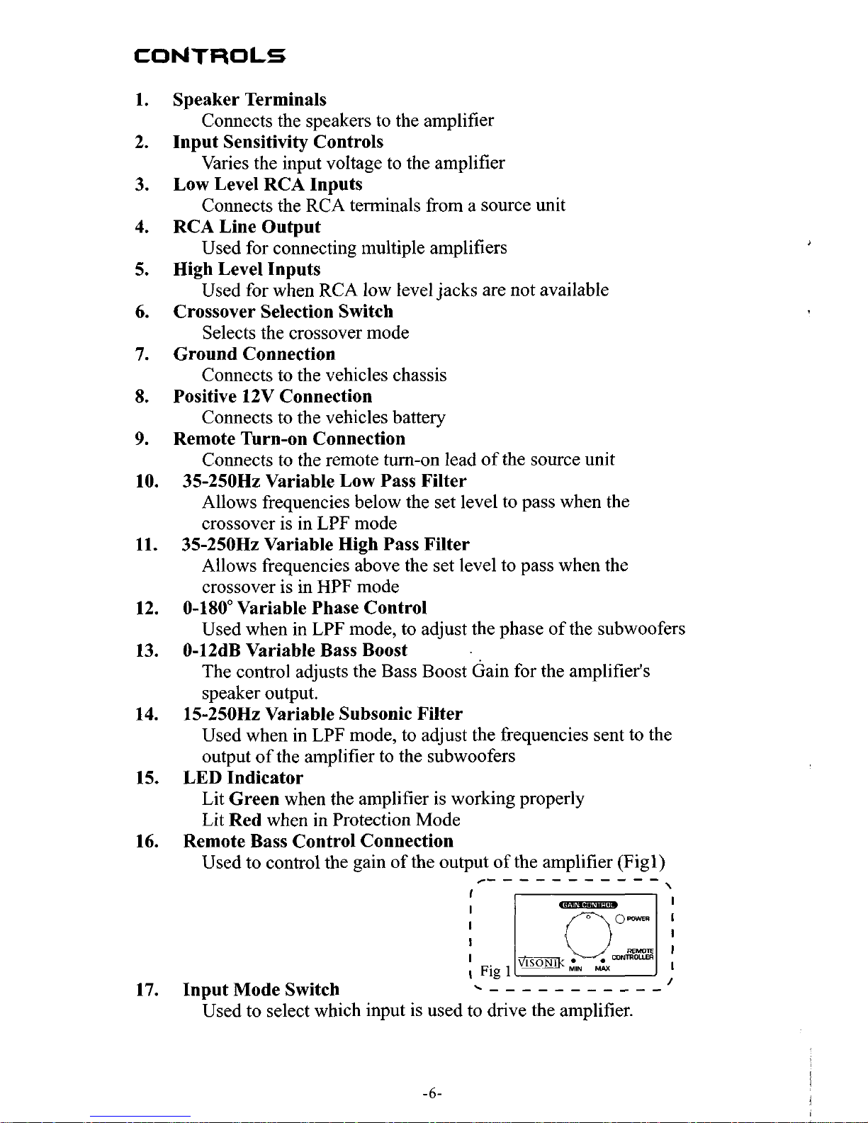
Speaker Terminals
Input Sensitivity Controls
Low Level RCA Inputs
RCA Line Output
High Level Inputs
Crossover Selection Switch
Ground Connection
Positive 12V Connection
Remote Turn-on Connection
Connects the speakers to the amplifier
Varies the input voltage to the amplifier
Connects the RCA terminals from a source unit
Used for connecting multiple amplifiers
Used for when RCA low level jacks are not available
Selects the crossover mode
Connects to the vehicles chassis
Connects to the vehicles battery
Connects to the remote turn-on lead of the source unit
Allows frequencies below the set level to pass when the
crossover is in LPF mode
Allows frequencies above the set level to pass when the
crossover is in
HPF
mode
0-180" Variable Phase Control
Used when in LPF mode, to adjust the phase of the subwoofers
0-12dB Variable Bass Boost
The control adjusts the Bass Boost Gain for the amplifier's
speaker output.
Used when in LPF mode, to adjust the frequencies sent to the
output of the amplifier to the subwoofers
Lit
Green
when the amplifier is working properly
Lit
Red
when in Protection Mode
Used to control the gain of the output of the amplifier (Figl)
35-250Hz Variable Low Pass Filter
35-250Hz Variable High Pass Filter
15-250Hz Variable Subsonic Filter
LED Indicator
Remote Bass Control Connection
_- - -
- - - -
- - -
-
I
\
AMPLIFIER
INPUT SENSITIVITY (LEVEL) CON
In order to achieve maximum signal-to-nc
adjust the signal level from your source
sensitivity. It is NOT a volume control. T
control by the external remote controller.
>
a. Set INPUT LEVEL controls at mid-po
b. Listen for audible distortion as you inc
c. If distortion is immediately heard, turn
POWER INPICSTOR
This GREEN LED will illuminate whene
it fails to illuminate, check the power co
PROTECTION CIRCUIT
Should the Amplifier become shorted,
protection circuit will "SHUT-DOWN"
turn "RED"
caused the problem is corrected. To reset
"OFF"
THIS AMPLIFIER IS DESIGNED TO
IMPEDANCE OF
THE AMPLIFIER TO IMPEDANCES L(
IS NOT COVERED UNDER WARRANT
Ohms
MAY CONSTITUTE
17.
.-
Input Mode Switch
k
- - - - - - -
- - -
-I
Used to select which input is used to drive the amplifier.
-6-
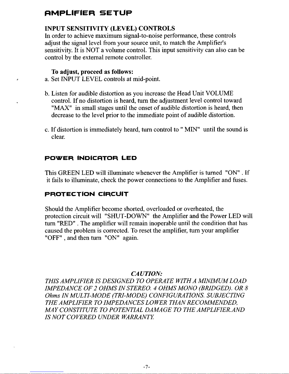
INPUT SENSITIVITY (LEVEL) CONTROLS
In order to achieve maximum signal-to-noise performance, these controls
adjust the signal level from your source unit, to match the Amplifier's
sensitivity. It is NOT a volume control. This input sensitivity can also can be
control by the external remote controller.
To
adjust, proceed as follows:
a. Set INPUT LEVEL controls at mid-point.
b. Listen for audible distortion as you increase the Head Unit VOLUME
control.
If
no distortion is heard,
turn
the adjustment level control toward
"MAX" in small stages until the onset of audible distortion is heard, then
decrease to the level prior to the immediate point of audible distortion.
c. If distortion is immediately heard, turn control to MIN" until the sound is
clear.
POWER
INDICATOR
LED
This GREEN LED will illuminate whenever the Amplifier is turned "ON" . If
it fails to illuminate, check the power connections to the Amplifier and fuses.
PROTECTION CIRCUIT
Should the Amplifier become shorted, overloaded or overheated, the
protection circuit will "SHUT-DOWN" the Amplifier and the Power LED will
turn
"RED"
. The amplifier will remain inoperable until the condition that has
caused the problem is corrected. To reset the amplifier,
turn
your amplifier
"OFF"
,
and then
turn
"ON"
again.
CAUTION:
THIS AMPLIFIER IS DESIGNED TO OPERATE WITH A MINIMUM LOAD
IMPEDANCE OF
2
OHMS IN STEREO. 4 OHMS MONO (BRIDGED). OR
8
Ohms
IN MULTI-MODE (TRI-MODE) CONFIGURATIONS. SUBJECTING
THE AMPLIFIER TO IMPEDANCES LOWER THAN RECOMMENDED,
MAY CONSTITUTE TO POTENTIAL DAMAGE TO THE AMPLIFIER.AND
IS NOT COVERED UNDER WARRANTY
-1-
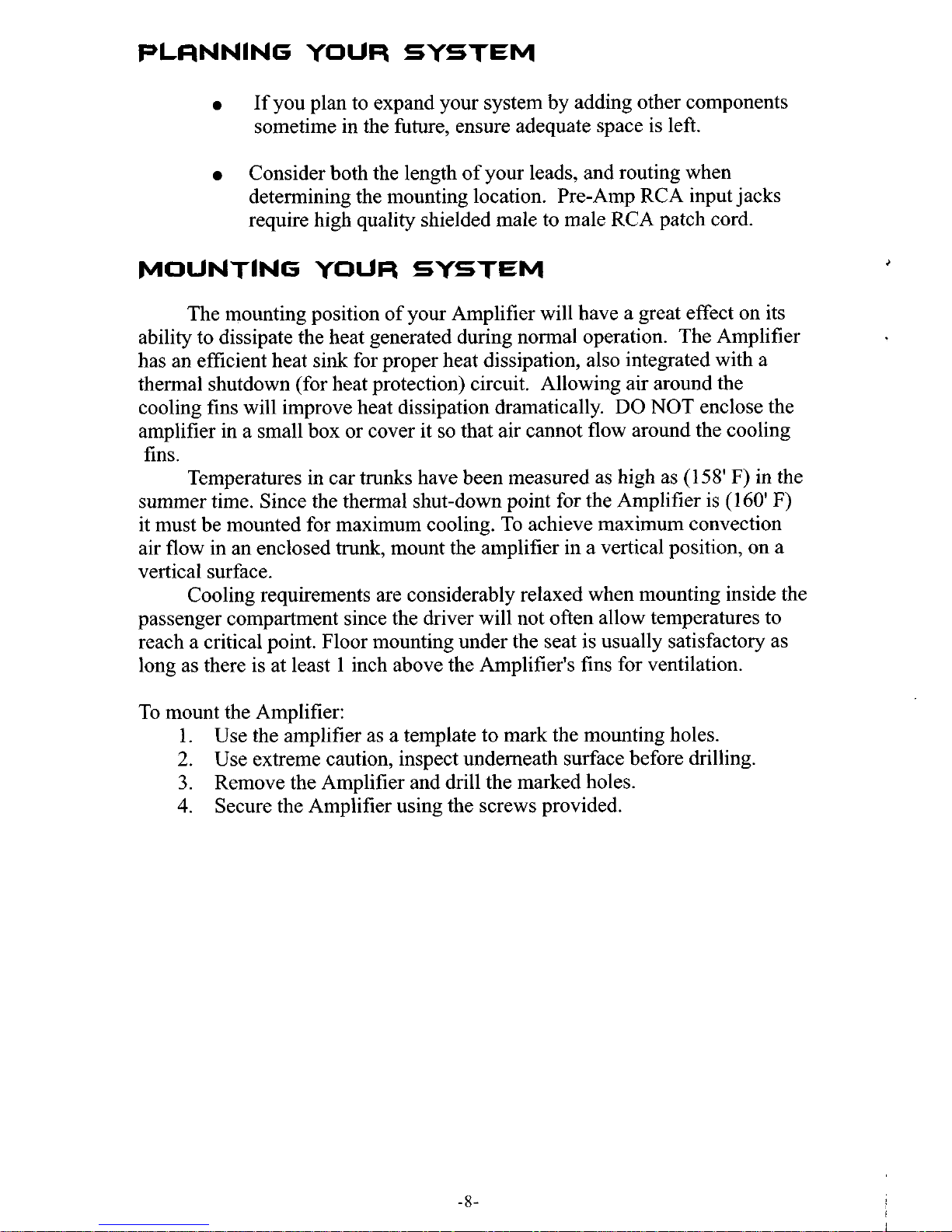
If you plan to expand your system by adding other components
sometime in the future, ensure adequate space is left.
Consider both the length of your leads, and routing when
determining the mounting location. Pre-Amp RCA input jacks
require high quality shielded male to male RCA patch cord.
MOUNTING
YOUR
SYSTEM
The mounting position of your Amplifier will have a great effect on its
ability to dissipate the heat generated during normal operation. The Amplifier
has an efficient heat sink for proper heat dissipation, also integrated with a
thermal shutdown (for heat protection) circuit. Allowing air around the
cooling fins will improve heat dissipation dramatically.
DO
NOT enclose the
amplifier in a small box or cover it
so that air cannot flow around the cooling
fins.
summer time. Since the thermal shut-down point for the Amplifier is (160'
F)
it must be mounted for maximum cooling.
To
achieve maximum convection
air flow in an enclosed
trunk,
mount the amplifier in a vertical position, on a
vertical surface.
passenger compartment since the driver will not often allow temperatures to
reach a critical point. Floor mounting under the seat is usually satisfactory as
long as there is at least
1
inch above the Amplifier's fins for ventilation.
To mount the Amplifier:
Temperatures in car trunks have been measured as high as (1
58'
F) in the
Cooling requirements are considerably relaxed when mounting inside the
1. Use the amplifier as a template to mark the mounting holes.
2.
Use extreme caution, inspect underneath surface before drilling.
3.
Remove the Amplifier and drill the marked holes.
4.
Secure the Amplifier using the screws provided.
NOTE.
DO
1.
2.
3.
J
4.
-8-
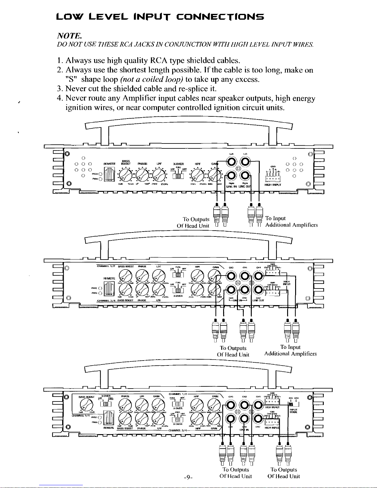
NOTE.
DO
NOT USE
THESE
RCA .JACKS
IN
CONJUNCTION WITH HIGH
LEVEL
INPUT
WIRES.
1.
Always use high quality RCA type shielded cables.
2.
Always use the shortest length possible. If the cable
is
too long, make on
3.
Never cut the shielded cable and re-splice it.
4.
Never route any Amplifier input cables near speaker outputs, high energy
"S"
shape loop
(not
a
coiled
loop)
to take up any excess.
1'
ignition wires, or near computer controlled ignition circuit units.
r
I
0
0
0
E-E
To
Outputs
ii
~~ToInp"t
Of
Head
Unit
Additional Amplifiers
To Outputs
To
Input
OfHead
Unit
Additional Amplificrs
To
Outputs
To
Outputs
-9-
Of Head
Unit
Of
Head
Unit
 Loading...