

Page 1
MCT
SMARTHOME.COM™ 1-800-SMART-HOME 949-221-9200 http://www.smarthome.com
Order#73951
SMARTHOME™ #73951
MCT-501
MCTMCT
-501
-501-501
Advanced Acoustic Sensor / PowerCode Transmitter
1111. INTRODUCTION
. INTRODUCTION
. INTRODUCTION. INTRODUCTION
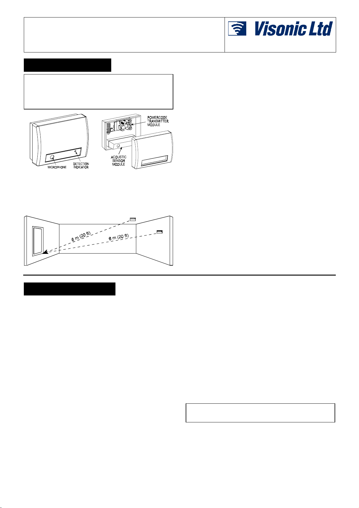
The MCT-501 combines two modules:
•••• The Sentrol Inc. ShatterPro™ acoustic sensor with Pattern
Recognition Technology™ (Protected under U.S. Patent
5,192,931)
•••• The Visonic Ltd. MCT-302 PowerCode™ transmitter
Figure 1. General View Figure 2. Module Identification
1.1 Acoustic Sensor
The acoustic sensor module of the MCT-501 is omni-directional,
providing 360° coverage. Coverage is measured from the sensor
to the point on the glass farthest from the sensor (see Fig. 3). The
sensor can be mounted as close as 1 m (3.3 ft) from the glass.
Figure 3. Typical Range Measurement
When mounted on opposite wall or adjoining walls, the range is
6 m (20 ft) for plate, tempered, laminated and wired glass.
When mounted on the ceiling, the maximum range is 6 m (20 ft)
for plate, tempered, laminated and wired glass
For armor-coated glass, mount the sensor no more than 3.65 m
(12 ft) from the glass.
1.2 PowerCode Transmitter
The acoustic sensor shares its housing with a miniature
transmitter which has a unique 24-bit PowerCode ID, selected in
the factory from over 16 million possible code combinations.
Upon alarm (glass break detection), a digital message is
transmitted, composed of the PowerCode ID followed by various
status and message-type markers. Alarm and other data are thus
forwarded to the wireless alarm control panel.
Since transmitted messages might collide with transmissions
from other PowerCode transmitters used in the system, a smart
anti-collision transmission sequence is used.
The MCT-501 is protected by a tamper switch that is activated
when the cover is removed. In a tamper situation, a message is
transmitted with the “tamper alert” marker ON.
A periodic supervision message, distinguished by a specific
marker, is transmitted automatically once in 60 minutes. The
wireless control panel is thus informed, at regular intervals, of the
sensor’s active participation in the system.
A red LED mounted on the transmitter PCB (visible only when the
cover is off) lights whenever alarm or tamper events are reported.
The LED does not light while a supervision message is being
transmitted.
Operating power is obtained from an on-board 3.6 V Lithium
Thionyl Chloride battery. A weak battery will cause a “low battery”
marker to be added to any message transmitted.
Installation Instructions
2222. SPECIFICATIONS
. SPECIFICATIONS
. SPECIFICATIONS. SPECIFICATIONS
ACOUSTIC SENSOR SECTION
Microphone: Omni-directional electret
Alarm Duration: 4 seconds
RF immunity: 20 V/m, 1 MHz to 1000 MHz
Temperature range: -10° to 50°C (14° to 120°F)
Recommended Glass Size:
Minimum: 0.3 x 0.6 m (1 x 2') or larger glass thickness
Plate: 2.4 to 6.4 mm (3/32 to 1/4")
Tempered: 3.2 to 6.4 mm (1/8 to 1/4")
Wired: 6.4 mm (1/4")
Laminated: 3.2 to 6.4 mm (1/8" to 1/4")
POWERCODE TRANSMITTER SECTION
Frequency (MHz): 315, 404, 418, 433.92 or other frequencies
according to local requirements.
Transmitter's ID Code: 24-bit digital word, over 16 million
combinations, pulse width modulation.
Overall Message Length: 36 bits
Message Repetition: One-shot transmission (default) or once
every 3 minutes.
Supervision: Signaling at 60-minute intervals (U.S. version) or
15 minute interval (UK version)
Response to Tamper Event: Tamper report every 3 minutes
(until the tamper switch is restored).
POWER SUPPLY
Power Source: 3.6 V Lithium Thionyl Chloride (LiSOCl2) battery,
size 1/2 AA, Tadiran TL-5902 or equivalent.
Nominal Battery Capacity: 1.2 Ah
Current Drain: 24 µA standby, 13 mA on alarm (including LED)
Battery Life (with LED on):
@ 10 transmissions per day:
@ 50 transmissions per day:
Battery Supervision:
as part of any status report.
PHYSICAL
Operating Temperature:
Dimensions:
Weight (less battery) :
Housing Material and Color: Flame retardant ABS, white
Standards:
The 418 & 433.92 MHz models of this device comply with the
European Council Directive EMC 89/336/EEC & 92/31/EEC, and
bear the CE mark and certification.
Meets FCC Part 15, ETS 300-220 and MPT1349
Automatic transmission of battery condition data
80 x 108 x 43 mm (3.13 x 4.24 x 1.70 in.).
130 g (4.6 oz)
Over 10 years
About 6 years
0°C to 49°C (32°F to 120°F).
DE3596 1
Page 2
3333. INSTALLATION
SMARTHOME.COM™ 1-800-SMART-HOME 949-221-9200 http://www.smarthome.com
Order#73951
. INSTALLATION
. INSTALLATION. INSTALLATION
3.1 Optimizing Detection and Avoiding
False Alarms
For best detection, avoid installing in:
!
Rooms with lined, insulating, or sound deadening drapes.
!
Rooms with closed wooden window shutters inside.
For best false alarm immunity:
!
Avoid 24-hour loop applications (perimeter loop OK).
!
Don't use where white noise, such as air compressor noise, is
present (a blast of compressed air may cause a false alarm).
!
Avoid rooms smaller than 3 x 3 m (10 x 10 ft) and rooms with
multiple noise sources such as small kitchens, glass booths
noisy areas, garages, small bathrooms, etc.
Areas to avoid:
!
Glass airlocks and glass vestibule areas
!
Noisy kitchens
!
Residential car garages
!
Small utility rooms
!
Stairwells
!
Small bathrooms
!
Other small acoustically live rooms. For glass break protection
in such applications, use shock sensors on the windows or
window frames.
Do Not Install In Humid Rooms The Wireless MCT-501 is not
hermetically sealed. Excess moisture on the circuit board can
eventually cause a short and a false alarm.
Avoid 24-Hour Loop Applications The MCT-501 is
recommended for perimeter loops and is designed to function in
occupied area. In 24-hour loop applications, where the sensor is
armed all day and all night, the false alarm prevention technology
will be pushed to its limit. Some sounds can duplicate the glass
break pattern the acoustic sensor detects.
Install the MCT-501 on a perimeter loop which is armed
whenever the door and window contacts are armed.
Protecting Occupied Areas
The false alarm immunity is best in rooms with only moderate
noise. For 24-hour occupied area protection, use shock sensors.
Proper Testing
The MCT-501 is designed to detect the breaking of framed glass
mounted in an outside wall. Testing the sensor with unframed
glass, broken bottles, etc., may not trip the sensor. The sensor
typically does not trip to glass breaking in the middle of the room.
No burglar breaks glass in the middle of a room, so such “breaks”
are false alarms.
NOTE: MCT-501 may not consistently detect cracks in glass, or
bullets which break through the glass. Glass-break sensors
should always be backed up by interior protection.
For best false alarm immunity the sensor should be located at
least 1.2 m (4 ft) away from noise sources (televisions, speakers,
sinks, doors, etc.). The sensor must always be in direct line of
sight of all protected windows. It cannot consistently detect glass
breaking around corners, in other rooms, etc. Front or back, up or
down orientation is not necessary.
3.3 Preparing the Unit
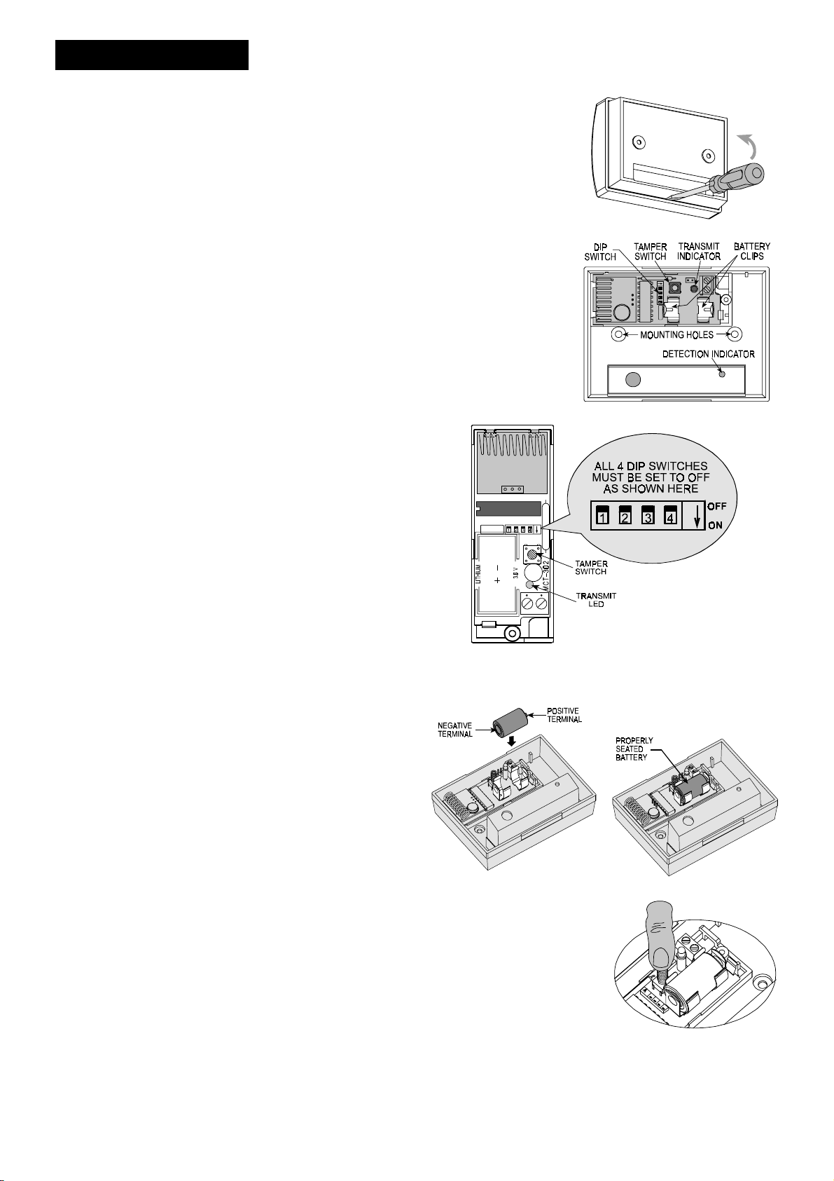
A. Use a screwdriver to
separate the cover
from the base, as
shown in Figure 4.
You will find inside a
nylon bag with the
battery, two masonry
anchors (wall plugs)
and two mounting
screws.
B. Get to know the
items indicated in
Fig. 5 - they are all
relevant to the steps
you will have to take
in the course of
installation.
C. Verify that all 4 DIP
switch levers are set
to OFF as shown in
Figure 6 below. If not
- set them all OFF.
Figure 6. DIP Switches - Correct Position
D. Insert the battery into the battery clips, as shown in Figures 7
and 8. Observe Polarity!
Figure 4. Opening the Unit
Figure 5. Inside View
Use only Lithium Thionyl Chloride
battery (Tadiran TL-5902 or
equivalent)
.
3.2 Sound Travel Considerations
Since the sound of breaking glass travels directionally out from
the broken window, the best location for mounting the sensor is
on the opposite wall - assuming the glass to be protected is within
the sensor's range and line of sight. The ceiling and adjoining
(side) walls are also good sensor locations. A ceiling mounted
sensor will have better detection if positioned 2 - 3 m (6 - 10 ft)
away from the protected glass into the room.
As with all glass-break sensors, detection is reduced with
same-wall mounting, since such detection is partially dependent
on glass break sound reflecting off the opposite wall. Test the
range with Sentrol 5709C unit held flat against the glass. There
may be a reduction in range, depending on room acoustics.
Figure 7. Battery Insertion
E. Click the tamper switch
once and release it to reset
the transmitter at power up.
Note: Since the cover is
removed and power is
applied, a tamper situation
exists. Verify that the
MCT-501 transmits (the
transmit LED lights briefly)
once every 3 minutes.
Figure 8. Battery in Place
Figure 9. Resetting the Unit
2 DE3596
Page 3
3.4 ID Enrollment and Mounting
SMARTHOME.COM™ 1-800-SMART-HOME 949-221-9200 http://www.smarthome.com
Order#73951
Note: It is much easier to enroll the transmitter ID while holding
the MCT-501 in your hand, close to the control panel.
A . Refer to the control panel’s or PowerCode receiver’s
installation instructions for enrolling transmitter IDs.
B . When required to initiate a transmission for enrolling the
transmitter’s ID, press the unit’s tamper switch and release it.
4444. TESTING PROCEDURES
. TESTING PROCEDURES
. TESTING PROCEDURES. TESTING PROCEDURES
The tamper message transmitted as a result (the transmit
LED blinks) will do the job.
C. Use the base as a template - press it against the wall at the
selected mounting position and mark the drilling points
through the mounting holes. Drill two holes and attach the
base to the wall using the wall plugs and screws.
D. Align the cover with the base and push it until it snaps shut.
4.1 How Does the Test Mode Works
The Pattern Recognition Technology™ of the MCT-501 ignores
most false alarm sounds, including glass-break testers. In order
to test the MCT-501, a test mode is used. With the sensor in the
test mode, processing of the glass-break pattern in the upper and
lower frequencies is disabled. The MCT-501 is then sensitive only
to the mid-range frequencies which the Sentrol 5709C hand-held
tester reproduces. It's the mid-range frequencies that determine
sensor coverage.
IN THE NORMAL MODE THE DETECTION LED FLASHES BRIEFLY
UPON RECEIVING A LOUD SOUND. WHEN IN THE NORMAL
MODE, THE MCT-501 WILL NOT TRIP TO THE TESTER’S SIGNAL,
UNLESS THE TESTER IS HELD NEXT TO THE SENSOR.
Each time the sensor alarms it also goes into the TEST mode
NOTE:
for one minute.
4.2 Switching the Sensor to the Test
Mode
Use the Sentrol 5709C or the Intellisense FG701 hand-held tester
to switch the sensor into the test mode. Set the tester to
tempered glass, hold the tester speaker directly on top of the
sensor and activate the tester. The sensor will alarm, then it will
go into test mode for one minute. When in test mode the LED on
the sensor will flash continuously. prolong the test session by
firing the tester at the sensor at least once a minute.
4.3 Testing the Sensor
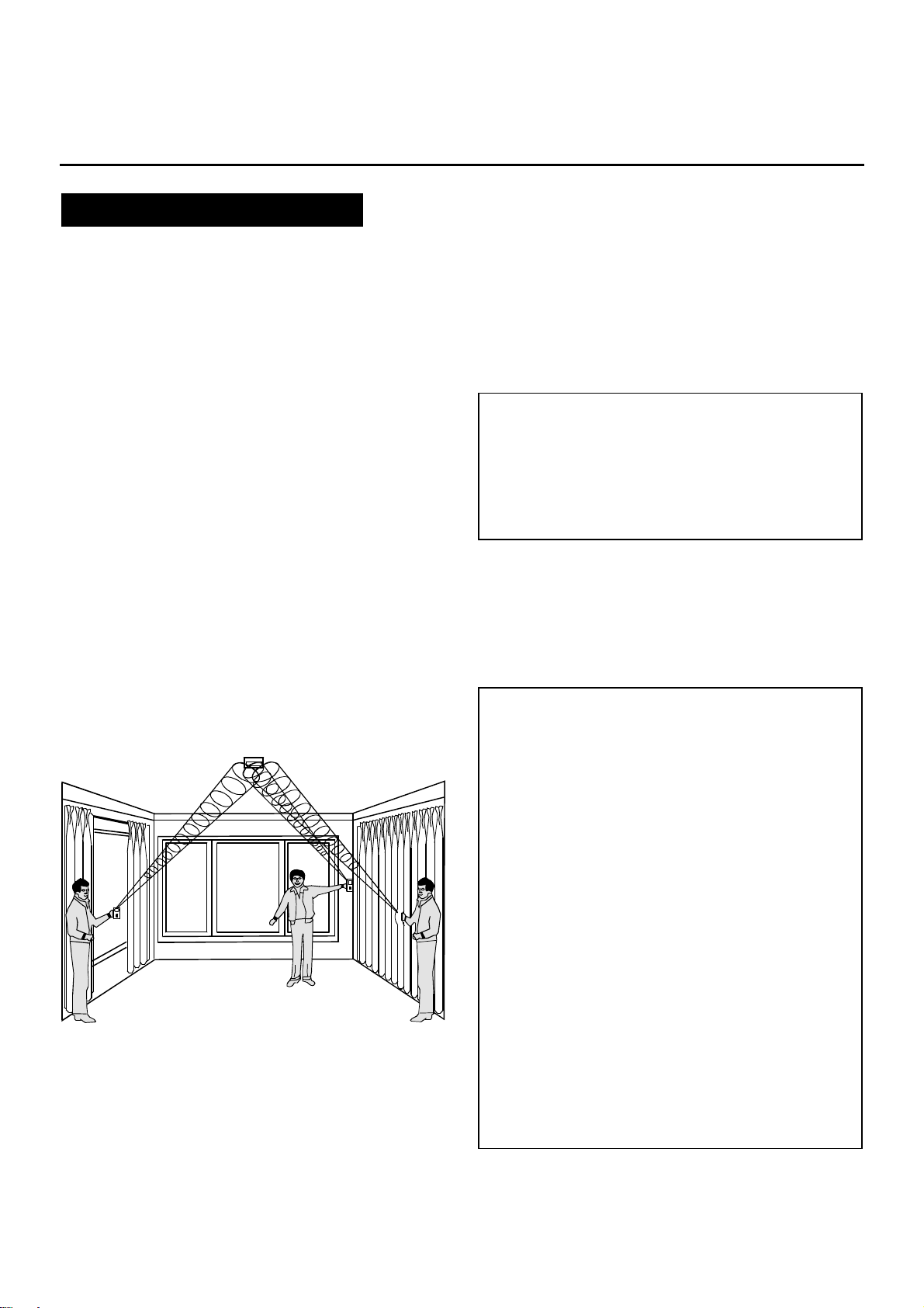
A. Holding the tester near the surface of the glass, aim the tester
at the MCT-501 and press the test button. If drapes or blinds
are present, test with the hand-held tester behind the closed
drapes or blinds (do not install the sensor where heavy or
lined drapes are used). If the sensor is mounted on same wall,
point the tester at the opposite wall.
Figure 10. Testing the MCT-501
B. The tester has a different setting for each type of glass. It
should always be set for tempered or laminated glass (either
is correct and both have the same range) unless you are
certain that all the protected glass is plate glass.
C. When the LED on the sensor goes solid momentarily while the
tester is triggered, the glass is within detection range.
(see Figure 10).
D. If the LED does not go solid, but continues flashing as before,
re-position the sensor closer to the protected windows and
retest. This may require adding sensors in order to achieve
adequate coverage. It is very rare that the sensor will not
activate within its stated range of coverage. Double check
adequate battery strength in the hand-held tester. A new
tester battery will likely restore the range.
Note: The sensor will automatically change from test mode to
normal mode approximately one minute after the last signal
received from the hand-held tester.
IMPORTANT! Room acoustics can artificially extend the
range of a glass-break sensor. The specified range of the
MCT-501 has been established for worst-case conditions.
While the sensor is likely to function at additional range, it
may miss a “minimum output” break, or room acoustics
may be changed at some future time, restoring sensor
coverage back to the normal range of 6 m (20 ft).
Do not exceed the rated range of the sensor, regardless of
what the tester shows.
4.4 Hand Clap Test
The MCT-501 can be checked by the installer or end user while
in normal mode, simply by clapping hands loudly under the
sensor. The LED will flash twice, but the sensor will not trip. This
verifies visually that there is power to the sensor, and that the
microphone and circuit board are functioning.
The hand clap activation is only momentary, so there is no
appreciable effect on battery life.
INSTALLATION TIPS
A. The MCT-501 is designed to detect the shattering of framed
glass mounted in an outside wall. “Testing" the sensor with
unframed glass, broken bottles, etc. may not trip the sensor.
The MCT-501 typically does not trip to glass break tests in
the middle of a room as such breaks are false alarms.
B. False alarms are most likely to occur when installed on a
24-hour loop in glass airlocks and glass vestibule areas, when
mounted above sinks, when used in residential car garages
and in other small, acoustically live rooms and rooms where
multiple sounds can reflect and eventually duplicate the glass
break frequency pattern. For occupied area glass break
protection in such applications, use shock sensors.
C. Installing the MCT-501 on 24-hour loops will increase false
alarms. The MCT-501 is recommended for perimeter loops
and is designed to function without false alarms in occupied
areas. On a 24-hour loop, which is armed all day/all night
every day, the false alarm technology will be pushed to its
limit since some sounds in some conditions can duplicate the
points on the glass break pattern that the MCT-501 detects.
Install the MCT-501 on a perimeter loop, which is armed
whenever the door and window contacts are armed. For
occupied area installations, MCT-501 's false alarm immunity
is best in rooms with only moderate noise.
D . MCT-501 detects the shattering of glass. Like all glass-break
sensors, it may not consistently detect cracks in glass, or
bullets that break through the glass or break out the glass.
Glass-break sensors should always be backed up by interior
protection.
DE3596 3
Page 4
5555. MISCELLANEOUS COMMENTS
SMARTHOME™ #73951
SMARTHOME.COM™ 1-800-SMART-HOME 949-221-9200 http://www.smarthome.com
Order#73951
. MISCELLANEOUS COMMENTS
. MISCELLANEOUS COMMENTS. MISCELLANEOUS COMMENTS
Visonic Ltd. wireless systems are very reliable and are tested to
high standards. However, due to their low transmitting power and
limited range (required by FCC and other regulatory authorities),
there are some limitations to be considered:
A. Receivers may be blocked by radio signals occurring on or near
their operating frequencies, regardless of the code selected.
B. A repeater can only respond to one transmitter signal at a time.
C. Wireless equipment should be tested regularly to determine
whether there are sources of interference and to protect
against faults.
This device complies with FCC Rules, Part 15. Operation is
subject to two conditions: (1) This device may not cause harmful
interference, and (2) this device must accept any interference
that may be received or that may cause undesired operation.
WARNING! Changes or modifications to this unit not expressly
approved by the party responsible for compliance could void the
user's authority to operate the equipment.
WARRANTY
WARRANTY
WARRANTYWARRANTY
Visonic Ltd. and/or its subsidiaries and its affiliates ("the Manufacturer") warrants its
products hereinafter referred to as "the Product" or "Products" to be in conformance with
its own plans and specifications and to be free of defects in materials and workmanship
under normal use and service for a period of twelve months from the date of shipment by
the Manufacturer. The Manufacturer's obligations shall be limited within the warranty
period, at its option, to repair or replace the product or any part thereof. The Manufacturer
shall not be responsible for dismantling and/or reinstallation charges. To exercise the
warranty the product must be returned to the Manufacturer freight prepaid and insured.
This warranty does not apply in the following cases: improper installation, misuse,
failure to follow installation and operating instructions, alteration, abuse, accident or
tampering, and repair by anyone other than the Manufacturer.
This warranty is exclusive and expressly in lieu of all other warranties, obligations or
liabilities, whether written, oral, express or implied, including any warranty of
merchantability or fitness for a particular purpose, or otherwise. In no case shall the
Manufacturer be liable to anyone for any consequential or incidental damages for breach
of this warranty or any other warranties whatsoever, as aforesaid.
This warranty shall not be modified, varied or extended, and the Manufacturer does not
authorize any person to act on its behalf in the modification, variation or extension of this
warranty. This warranty shall apply to the Product only. All products, accessories or
attachments of others used in conjunction with the Product, including batteries, shall be
covered solely by their own warranty, if any. The Manufacturer shall not be liable for any
damage or loss whatsoever, whether directly, indirectly, incidentally, consequentially or
otherwise, caused by the malfunction of the Product due to products, accessories, or
attachments of others, including batteries, used in conjunction with the Products.
The digital circuitry of this device has been tested and found to
comply with the limits for a Class B digital device, pursuant to Part 15
of the FCC Rules. These limits are designed to provide reasonable
protection against harmful interference in residential installations.
This equipment generates, uses and can radiate radio frequency
energy and, if not installed and used in accordance with the
instructions, may cause harmful interference to radio and television
reception. However, there is no guarantee that interference will not
occur in a particular installation. If this device does cause such
interference, which can be verified by turning the device off and on,
the user is encouraged to eliminate the interference by one or more
of the following measures:
– Re-orient or re-locate the receiving antenna.
– Increase the distance between the device and the receiver.
– Connect the device to an outlet on a circuit different from the one
which supplies power to the receiver.
– Consult the dealer or an experienced radio/TV technician.
The Manufacturer does not represent that its Product may not be compromised and/or
circumvented, or that the Product will prevent any death, personal and/or bodily injury
and/or damage to property resulting from burglary, robbery, fire or otherwise, or that the
Product will in all cases provide adequate warning or protection. User understands that a
properly installed and maintained alarm may only reduce the risk of events such as
burglary, robbery, and fire without warning, but it is not insurance or a guarantee that such
will not occur or that there will be no death, personal damage and/or damage to property
as a result.
The Manufacturer shall have no liability for any death, personal and/or bodily injury
and/or damage to property or other loss whether direct, indirect, incidental,
consequential or otherwise, based on a claim that the Product failed to function.
However, if the Manufacturer is held liable, whether directly or indirectly, for any loss or
damage arising under this limited warranty or otherwise, regardless of cause or origin, the
Manufacturer's maximum liability shall not in any case exceed the purchase price of the
Product, which shall be fixed as liquidated damages and not as a penalty, and shall be the
complete and exclusive remedy against the Manufacturer.
Warning: The user should follow the installation and operation instructions and among
other things test the Product and the whole system at least once a week. For various
reasons, including, but not limited to, changes in environmental conditions, electric or
electronic disruptions and tampering, the Product may not perform as expected. The user
is advised to take all necessary precautions for his/her safety and the protection of his/her
property.
6/91
VISONIC LTD. (ISRAEL): P.O.B 22020 TEL-AVIV 61220 ISRAEL. PHONE: (972-3) 645-6789, FAX: (972-3) 645-6788
VISONIC INC. (U.S.A.): 10 NORTHWOOD DRIVE, BLOOMFIELD CT. 06002-1911. PHONE: (860) 243-0833, (800) 223-0020 FAX: (860) 242-8094
VISONIC LTD. (UK): UNIT 1, STRATTON PARK, DUNTON LANE, BIGGLESWADE, BEDS. SG18 8QS. PHONE: (01767) 600857 FAX: (01767) 601098
INTERNET WEB SITE:
VISONIC LTD. 2000 MCT-501 DE3596- (REV. 0, 2/00)
www.visonic.com
4 DE3596
 Loading...