

Page 1
DE2231 1
WT
WTWT
WT-211
-211-211
-211
Waterproof Wrist Transmitter
Installation Instructions
1111. INTRODUCTION
. INTRODUCTION. INTRODUCTION
. INTRODUCTION
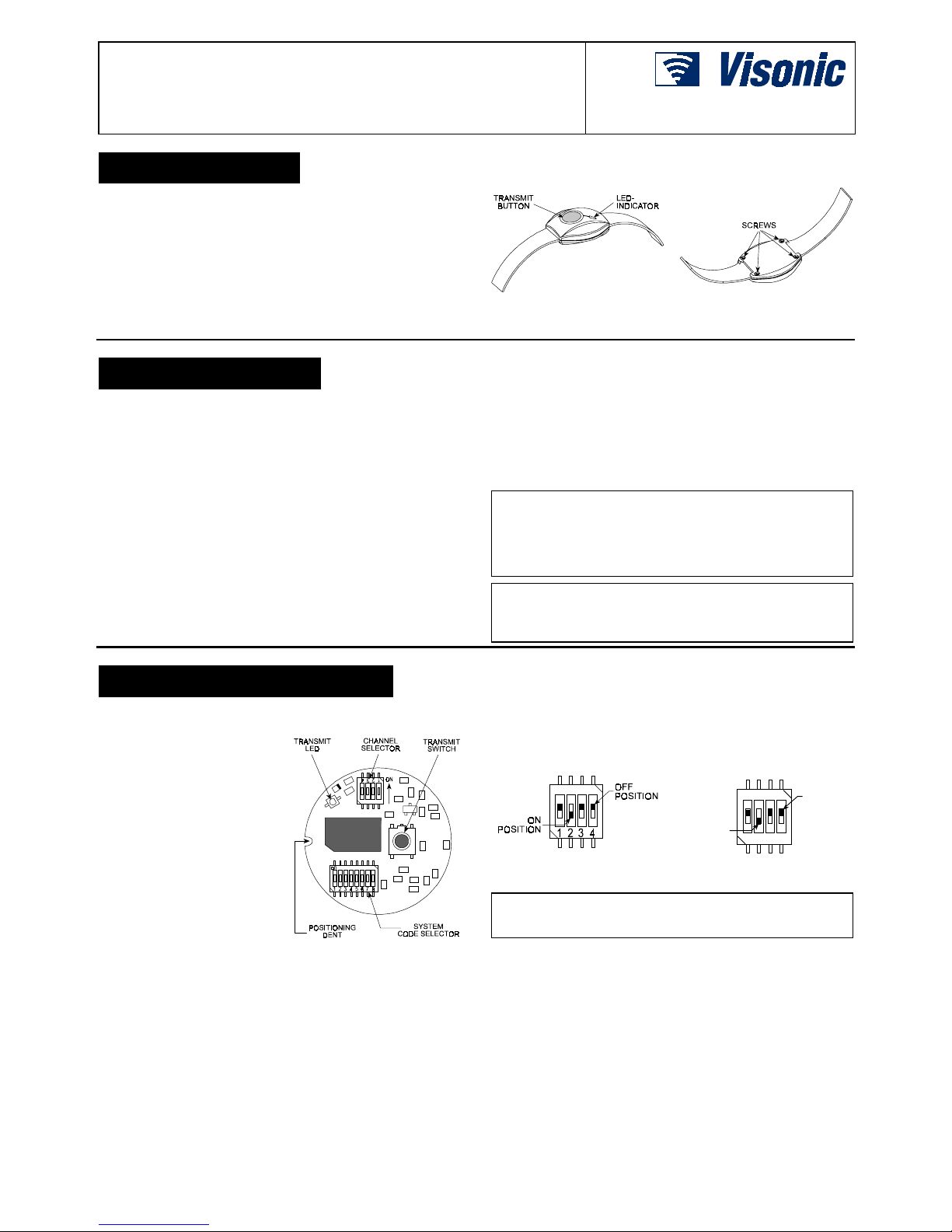
The WT-211 is a miniature water-proof wrist-worn transmitter,
designed to send coded transmissions to wireless receivers of
the WR-200 and W R-300 series. Transmission is activated by
depressing the pushbutton at the center of the unit.
All WT-211 units are supplied with a wrist band, to be worn like a
regular watch. Operating power is obtained from a coin-type,
3-volt lithium battery that can last up to 10 years.
A LED lights during transmission, indicating that the battery
voltage exceeds 2.7 V. If the LED lights dimly or does not light at
all during transmission, the battery must be replaced immediately.
Figure 1. WT-211, General
View
Figure 2. Opening the Case
2222. SPECIFICATIONS
. SPECIFICATIONS. SPECIFICATIONS
. SPECIFICATIONS
Frequency (MHz): 315, 404, 418, 433.92 or other frequencies
according to local requirements.
Modulation: ASK (ON-OFF keying)
System Code: 8-bit digital word, 256 possible code
combinations, pulse width modulation.
Channel Code: 4-bit digital word
Transmit Duration: Continuous, for as long as the pushbutton is
being pressed.
Power Supply: 3-volt Lithium cell (Sanyo type CR-2025 or
equivalent).
Nominal Battery Capacity: 150 mAh
Current Consumption: 2 mA (during transmission only).
Battery Life: 3 to 5 years with about 3 transmissions per day; up
to 10 years with one transmission per day or none at all.
Battery Check:
Good battery - LED lights steadily upon transmission.
Low battery - LED lights dimly or not at all upon transmission.
Low Battery Threshold: 2.7 VDC
Operating Temperature: 0° to 50°C (32° to 122°F).
Dimensions: Ø 35 mm (1.4 in.).
Weight: 25 g (0.9 oz).
Color: Watch - black, button - turquoise.
Standards: Meets FCC part 15, MPT1340 and RTTE requirements
This device complies with Part 15 of the FCC Rules and
RSS-210 of Industry and Science Canada. Operation is subject
to the following two conditions: (1) This device may not cause
harmful interference, and (2) this device must accept any
interference received, including interference that may cause
undesired operation.
This device complies with the essential requirements and
provisions of Directive 1999/5/EC of the European Parliament and
of the Council of 9 March 1999 on radio and telecommunications
terminal equipment.
3333. PREPARATION FOR USE
. PREPARATION FOR USE. PREPARATION FOR USE
. PREPARATION FOR USE
3.1 Opening the Case
A. Put the transmitter face down.
B. Loosen and remove the 4
screws where shown in
Figure 2. Take care not to
lose the screws.
C. Turn the transmitter over.
Hold the base between the
fingers of one hand, and pull
the cover off.
D. Make sure that the rubber
ring that serves as a seal is
in place around the rim of
the base. If it comes loose,
save it for later use together
with the screws.
Note: The strap pivots are
seated in open grooves at
the two edges of the base.
Figure 3. Transmitter Module
- Top Side
If you put the base on the table "on its back", the pivots and
the two sections of the strap will remain in place.
Upon removal of the cover, the top side of the transmitter module
can be viewed (Fig. 3).
3.2 System Code Selection
A miniature 8-position DIP switch with levers marked "1" to "8" is
used to select the SYSTEM code - a "password" between the
WT-211 and the target receiver.
Each lever on this switch may be set to ON or OFF, to obtain one
of the 256 possible code combinations. The digital code selected
must match the code setting of the target receiver.
Use a ball point pen or a similar pointed object to shift the switch
levers to the positions producing the desired system code (Fig. 4).
Figure 4. System Code
Selector
1234
ON
POSITION
OFF
POSITION
Figure 5. Channel Code
Selector
Important: The factory test code shown in Figure 4 (2, 4, 5, 6, 7
ON / 1, 3, 8 OFF) must not be used. Also avoid codes such as:
all keys ON, all keys OFF or alternating ON/OFF settings.
3.3 Channel Code Selection
A 4-position DIP switch with levers marked "1" to "4" is used to
select the CHANNEL code transmitted by the WT-211. Each
transmitter can be set to activate any one of the outputs or
"channels" of a 4-output receiver. This way, different zones of an
alarm control panel may be activated via a multi-channel receiver.
The channel code is selected by shifting the lever marked with
the desired channel number to ON (Fig. 5).
Use a ball point pen to set the channel selector as required by the
host system.
Page 2
2 DE2231
CAUTION! disregard the "ON" mark on the
channel switch body. The true ON position for
each channel is with the lever set close to the
channel number.
3.4 Closing the Case
A. Check that the rubber ring is in place around the rim of the
base. If not, place it carefully around the rim.
B. Align the cover with the base: make sure that the transparent
lens is over the transmit LED and the transmit pushbutton is
over the transmit switch (Fig. 3). Then press the cover and the
base together between your fingers.
C. Turn the reassembled unit upside down, and while keeping
both halves of the case pressed together, insert the four
screws and tighten them well.
4444. TESTING AND MAINTENANCE
. TESTING AND MAINTENANCE. TESTING AND MAINTENANCE
. TESTING AND MAINTENANCE
4.1 Testing a New Unit
A. Stand 3 m (10 ft) away from the receiver and operate the
transmitter by depressing its transmit pushbutton.
B. Verify that the transmitter LED lights, indicating good battery
condition.
C. Observe that the target receiver LED lights, indicating
detection of the transmitted RF signal.
D. In the target receiver, verify activation of the particular output
relay associated with the transmitted channel code.
E. Operate the transmitter from various locations within the area
covered by the target receiver to determine "dead" locations,
where transmission is blocked by walls and large objects, or
affected by structural materials.
Note: If dead/marginal zones are a problem, relocating the
receiver may improve the performance.
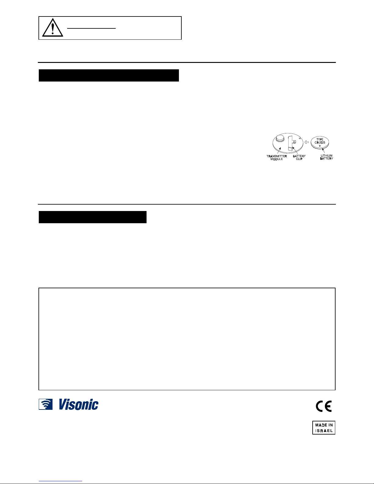
4.2 Replacing the Battery
The original battery supplied with the transmitter can last up to 10
years if used sparingly (only a single transmission per day).
Battery replacement will therefore be needed very rarely.
A . Open the case as directed in Para. 3.1. The battery clip and
the battery will be out of sight - they are both located on the
bottom (hidden) side of the module.
B. Grasp the transmit switch with two fingers. Lift the
transmitter module out of the base and turn it over. The
bottom side of the module can now be viewed.
C . Slide the old battery from under the clip in the opposite
direction to the arrow shown in Figure 6.
D. Hold the 3-volt lithium
replacement battery (type
CR-2025 or equivalent) with
the positive (+) side up.
Slide the battery all the way
in under the battery clip
until it stops.
E. Turn the transmitter module
Figure 6. Battery Insertion
over and briefly press the transmit switch (Fig. 3).The
on-board LED should light brightly while the switch is pressed.
F. Align the positioning dent (Fig. 3) with the guide pin in the
base and place the module within the base. Then close the
case as instructed in Para. 3.4 above).
5555. GENERAL COMMENTS
. GENERAL COMMENTS. GENERAL COMMENTS
. GENERAL COMMENTS
Our wireless systems are very reliable and are tested to high
standards. However, due to their low transmitting power (required
by FCC, DTI and other regulatory authorities) there are some
limitations to be considered:
A. Receivers may be blocked by radio signals on or near their
operating frequencies, regardless of the code selected.
B. A receiver can only respond to one transmitted signal at a time.
C. Wireless equipment should be tested regularly (at least once
a week) to determine if there are sources of interference and
to protect against faults.
WARNING: Changes or modifications to this unit not
expressly approved by the party responsible for compliance
could void the user's authority to operate the equipment.
4.3 Frequency Allocations for Wireless
Devices in European (EU) Countries
• 433.92 MHz has no restriction in any EU member state.
• 418 MHz is allowed in the UK only.
• 315 MHz is not allowed in any EU member state
WARRANTY
WARRANTYWARRANTY
WARRANTY
Visonic Ltd. and/or its subsidiaries and its affiliates ("the Manufacturer") warrants its
products hereinafter referred to as "the Product" or "Products" to be in conformance with
its own plans and specifications and to be free of defects in materials and workmanship
under normal use and service for a period of twelve months from the date of shipment by
the Manufacturer. The Manufacturer's obligations shall be limited within the warranty
period, at its option, to repair or replace the product or any part thereof. The Manufacturer
shall not be responsible for dismantling and/or reinstallation charges. To exercise the
warranty the product must be returned to the Manufacturer freight prepaid and insured.
This warranty does not apply in the following cases: improper installation, misuse,
failure to follow installation and operating instructions, alteration, abuse, accident or
tampering, and repair by anyone other than the Manufacturer.
This warranty is exclusive and expressly in lieu of all other warranties, obligations or
liabilities, whether written, oral, express or implied, including any warranty of
merchantability or fitness for a particular purpose, or otherwise. In no case shall the
Manufacturer be liable to anyone for any consequential or incidental damages for breach
of this warranty or any other warranties whatsoever, as aforesaid.
This warranty shall not be modified, varied or extended, and the Manufacturer does not
authorize any person to act on its behalf in the modification, variation or extension of this
warranty. This warranty shall apply to the Product only. All products, accessories or
attachments of others used in conjunction with the Product, including batteries, shall be
covered solely by their own warranty, if any. The Manufacturer shall not be liable for any
damage or loss whatsoever, whether directly, indirectly, incidentally, consequentially or
otherwise, caused by the malfunction of the Product due to products, accessories, or
attachments of others, including batteries, used in conjunction with the Products.
The Manufacturer does not represent that its Product may not be compromised and/or
circumvented, or that the Product will prevent any death, personal and/or bodily injury
and/or damage to property resulting from burglary, robbery, fire or otherwise, or that the
Product will in all cases provide adequate warning or protection. User understands that a
properly installed and maintained alarm may only reduce the risk of events such as
burglary, robbery, and fire without warning, but it is not insurance or a guarantee that such
will not occur or that there will be no death, personal damage and/or damage to property
as a result.
The Manufacturer shall have no liability for any death, personal and/or bodily injury
and/or damage to property or other loss whether direct, indirect, incidental,
consequential or otherwise, based on a claim that the Product failed to function.
However, if the Manufacturer is held liable, whether directly or indirectly, for any loss or
damage arising under this limited warranty or otherwise, regardless of cause or origin, the
Manufacturer's maximum liability shall not in any case exceed the purchase price of the
Product, which shall be fixed as liquidated damages and not as a penalty, and shall be the
complete and exclusive remedy against the Manufacturer.
Warning: The user should follow the installation and operation instructions and among
other things test the Product and the whole system at least once a week. For various
reasons, including, but not limited to, changes in environmental conditions, electric or
electronic disruptions and tampering, the Product may not perform as expected. The user
is advised to take all necessary precautions for his/her safety and the protection of his/her
property.
6/91
VISONIC LTD. (ISRAEL): P.O.B 22020 TEL-AVIV 61220 ISRAEL. PHONE: (972-3) 645-6789, FAX: (972-3) 645-6788
VISONIC INC. (U.S.A.): 10 NORTHWOOD DRIVE, BLOOMFIELD CT. 06002-1911. PHONE: (860) 243-0833, (800) 223-0020 FAX: (860) 242-8094
VISONIC LTD. (UK): FRASER ROAD, PRIORY BUSINESS PARK, BEDFO RD MK44 3WH. PHONE: (0870) 730-0800 FAX: (0870) 730-0801
INTERNET: WWW.VISONIC.COM
VISONIC LTD. 2001 WT-211 D-2231-0 NEW: DE2231- (REV. 1, 6/01)
 Loading...