

Page 1
:7:7:3
PENDANT TRANSMITTERS
,1752'8&7,21
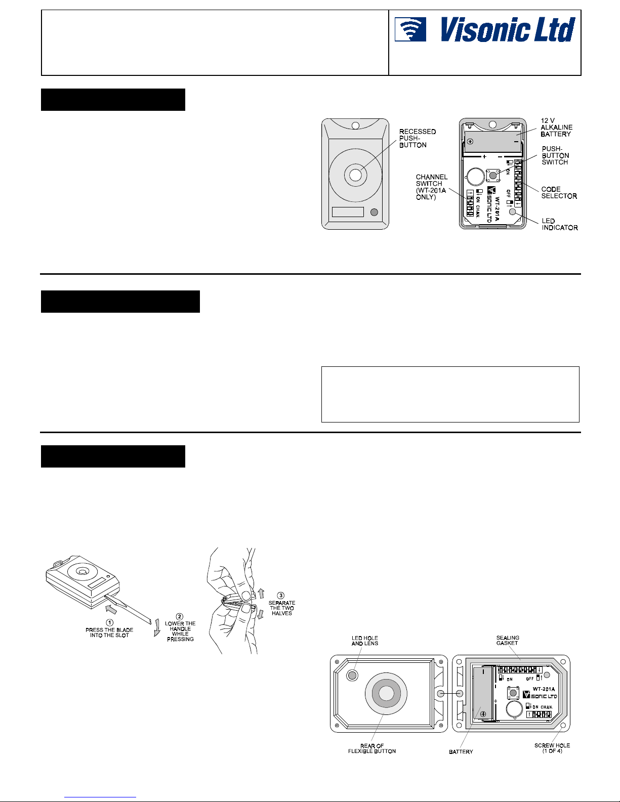
The WT-201 is a series of miniature transmitters, designed to
send coded transmissions to wireless receivers of the WR-200
and WR-300 series . Transmissi on is activat ed by depressing the
recessed pushbutton at the cent er of the unit. Transmitters with
an A-suffix are equipped with a 4-channel selector. The
WT-201WP is a water proof version of the WT-201.
All WT-201 unit s ar e s uppli ed wit h t he chai n i nst all ed, to be wor n
around the neck as a pendant transmitter. A key ring is also
included in the package, for use in pl ace of the chain. Oper ating
power is obtained from a cylindrical 12-volt alkaline battery
(Duracell MN-21, Golden Power GP-23A or equivalent).
A LED lights during transmission, indicating the battery voltage
condition (lights when batt ery vol tage exceeds 8 VDC) . If the LED
does not light during transmis sion, the battery must be r eplaced
immediately.
63(&,),&$7,216
Frequency (MHz): 315, 304, 404, 418, 433.92 or other frequencies accor ding to local requirements.
Encoding:
WT-201: 12-bit digital word, 256 combinations (using first 8
bits), pulse width modulation.
WT-201A: 12-bit digit al word, 256 combinations plus selection
of up to 16 channels (using last 4 bits).
Power Supply: 12-volt alkal ine battery (Durac ell MN-21, Golden
Power GP-23A, or equivalent).
Attention: Transmitt er charact erist ics may be af fected by battery
condition.
Installation Instructions
Figure 1. WT-201 with Cover Removed
Operating Temperatur e: 0° to 49°C (32° to 120°F).
Dimensions: 32 x 53 x 17 mm (1-1/4 x 2-1/8 x 11/16 in.).
Weight: 22 g (0.7 oz).
Color: White.
Compliance with Standards: Meet s the requirements of FCC
Part 15. FCC ID: GSAWT201C
CANADA: 1467 101 534.
Also meets MPT-1340, ETS 300 220, ETS 300 339 and ETS
300 683.
,167$//$7,21
%DWWHU\,QVWDOODWLRQ
A. WT-201 and WT-201A
Insert an 1/8 inch screwdriver blade in the slot at the bottom of
(1)
the case, and follow the steps shown in Figure 2.
Warning! Do not open the case by insert ing a screwdriver in
places other than the slot. This can damage the transmitter.
Figure 2. Opening the Case
Insert the 12-vol t alkaline battery (Dur acell MN-21 or Golden
(2)
Power GP-23A or equivalent) between the battery clips, so
that the (+) and (–) markings on t he battery coinci de with the
markings near eac h batt ery c l ip - s ee Figur e 1. Chec k t hat t he
battery is held securely by the battery clips.
Gently press the pushbutton switch and verify that the LED
(3)
lights, indi cating good battery condition.
Carefully engage the ri dges at the top end of the rear cover
(4)
with the dents at t he top end of the front cover. Gently press
together the bottom ends of both covers, until they snap shut.
B. Waterproof Version WT-201WP
Waterpr oof units are shipped fully as sembled but not closed, to
permit insertion of the battery before final sealing. The case is
made waterproof when its two halves are assembled and secured
together with 4 screws. To prepare the unit for use:
Separate the two halves of the cas e and lay t he unit down on
(1)
its back as s hown in Fi gure 3. I nser t the 12
the battery cli ps. Observe polari ty!
Gently press the pushbutton switch and verify that the LED
(3)
lights, indi cating good battery condition.
Reassemble the two halves of the case and lay the unit fac e
(4)
down. Put a screw in each of the four holes on the back
(screws are supplied in a small bag packed with the unit).
Carefully tighten all 4 screws with phillips screwdriver No. 1.
The unit should now be watert ight and ready for use.
Figure 3. Inside Vi ew of the WT-201WP
V battery between
DE2061 1
Page 2
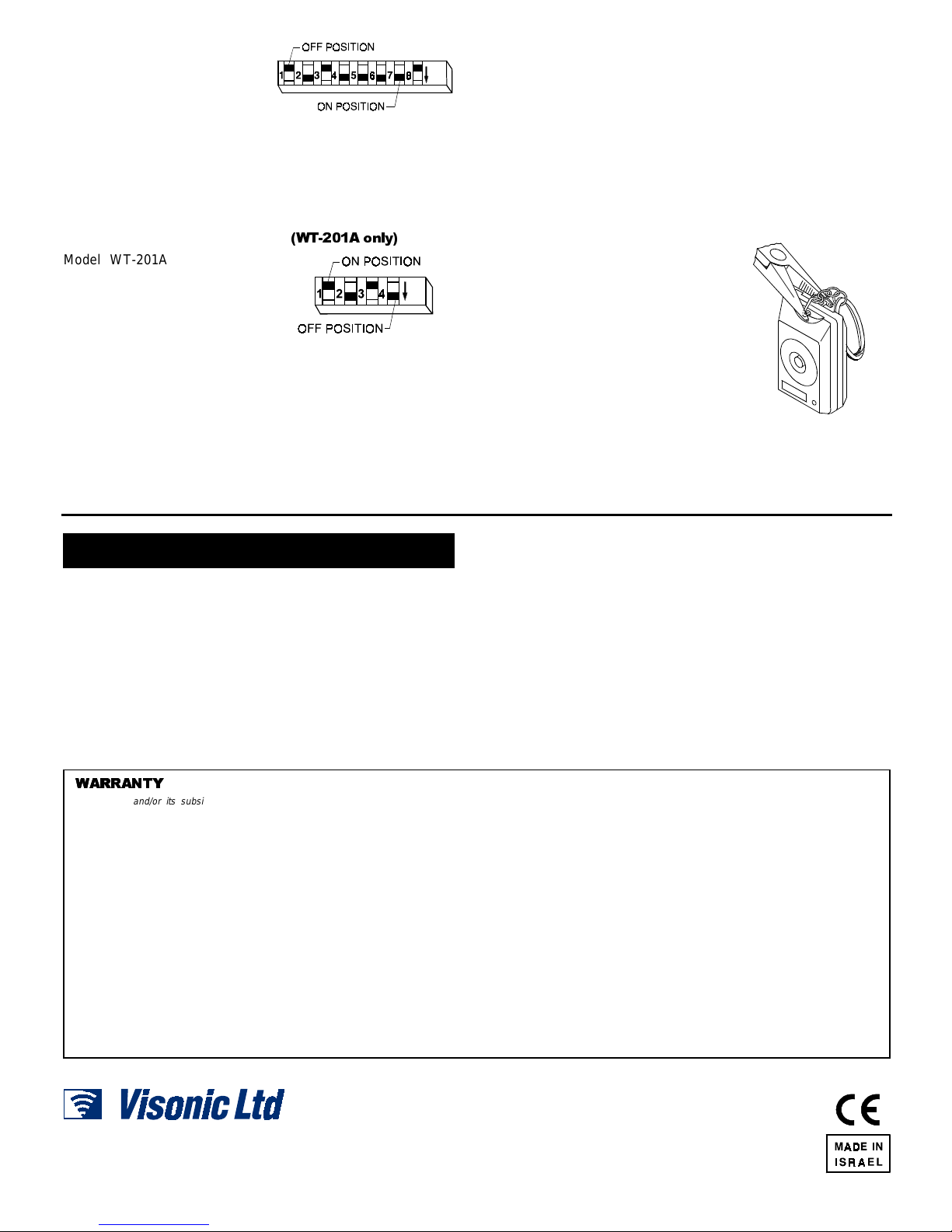
&RGLQJ
All WT-201 units have an
8-key DIP switch (mar ked 1 to
8). Each switch may be set t o
ON or OFF position, to c reate
a unique digital system code see Figure 4.
Figure 4. Code Selector
Use a ball point pen to set each of the switches to match the
code setting of the companion receiver.
CAUTION: The factory tes t code (2, 4, 5, 6, 7 ON / 1, 3, 8 OFF)
must not be used. Also avoid codes which are often OFF or
alternating ON/OFF used: all keys ON, all keys sett ings.
&KDQQHO6HOHFWLRQ
:7$ RQO\
Model WT-201A is equipped
with a 4-channel selector
marked CHAN (see Figure 5).
Using this switch you can set
the transmitter for activating
one of four outputs at the
receiver. This feature is
important for zoning purposes
Figure 5. Channel Select or
- activating different alarm zones of a control panel via a
companion, multi-c hannel receiver. The channel dat a transmi tted
by the WT-201A is selected by positioning the 4 switches in
accordance with the r equired channel number. Use a ball point
pen to set the channel selector as r equired by the host sys tem.
7HVWLQJ
A. Stand 10 feet away from the receiver and operate the
transmitter.
B. Verify t hat the transmitter LED l ights, indicating good battery
condition.
C. Observe that the receiver LED li ghts, indicating detection of
the transmitted RF signal.
D. Verify activation of the rec eiver's output relay assoc iated with
the channel selected in the transmitter (the WT-201
single-channel tr ansmitter operates the relay as sociated with
channel 1).
E. Operate the transmitter from various locations within the area
covered by the receiver to determine "dead" locations , where
transmission is obstructed by walls and large objects, or
affected by structural materials.
.H\5LQJ,QVWDOODWLRQ
A. Remove the chain by opening and
slipping it through the triangle on
top of the WT-201.
B. Insert the tip of a long-nose pliers
into the triangle and open it.
C. Remove the triangle.
D. Open the plastic bag which
contains the key-ring kit.
E. Slip the key-ring triangle through
the last link of the key-ring chain
and install the triangle into the
hole on the top of the WT-201
(Figure 6).
F. Using the pliers, close the key-ring triangle.
Figure 6. Key-Ring
Installation
0,6&(//$1(286&200(176
3URGXFW/LPLWDWLRQV
Our wireless systems are very reliable and are tested to high
standards. However, due to t heir low t rans mi tt ing power ( r equir ed
by FCC regulations) there are some limitations to be considered:
A. Receivers may be blocked by radio signals occurring on or
near their operating frequencies, regardless of the code
selected.
B. A receiver can respond to one transmitted signal at a time.
C. Wireless equipment should be t ested regularly (at l east once
a week) to determine if there are s ources of inter ference and
to protect against faults.
:$55$17<
:$55$17<
Visonic Ltd. and/or its subsidiaries and its affiliates ("the Manufacturer") warrants its
products hereinafter referred to as "the Product" or "Products" to be in conformance with
its own plans and specifications and to be free of defects in materials and workmanship
under normal use and service for a period of twelve months from the date of shipment by
the Manufacturer. The Manufacturer's obligations shall be limited within the warranty
period, at its option, to repair or replace the product or any part thereof. The Manufacturer
shall not be responsible for dismantling and/or reinstallation charges. To exercise the
warranty the product must be returned to the Manufacturer freight prepaid and insured.
This warranty does not apply in the following cases: improper installation, misuse,
failure to follow installation and operating instructions, alteration, abuse, accident or
tampering, and repair by anyone other than the Manufacturer.
This warranty is exclusive and expressly in lieu of all other warranties, obligations or
liabilities, whether written, oral, express or implied, including any warranty of
merchantability or fitness for a particular purpose, or otherwise. In no case shall the
Manufacturer be liable to anyone for any consequential or incidental damages for breach
of this warranty or any other warranties whatsoever, as aforesaid.
This warranty shall not be modified, varied or extended, and the Manufacturer does not
authorize any person to act on its behalf in the modification, variation or extension of this
warranty. This warranty shall apply to the Product only. All products, accessories or
attachments of others used in conjunction with the Product, including batteries, shall be
covered solely by their own warranty, if any. The Manufacturer shall not be liable for any
damage or loss whatsoever, whether directly, indirectly, incidentally, consequentially or
otherwise, caused by the malfunction of the Product due to products, accessories, or
attachments of others, including batteries, used in conjunction with the Products.
&RPSOLDQFHZLWK 6WDQGDUGV
WARNING: Changes or modifications to this unit not
expressly approved by the party responsible for compl iance
could void the user's authority to operate the equipment.
The 315 MHz model of this device c omplies with Part 15 of the
FCC Rules and RSS-210 of Industry and Science Canada.
Operation is subject to the following two conditions: (1) This
device may not cause harmful interference, and (2) this device
must accept any interference that may be received, including
interference that may cause undesired operation.
The Manufacturer does not represent that its Product may not be compromised and/or
circumvented, or that the Product will prevent any death, personal and/or bodily injury
and/or damage to property resulting from burglary, robbery, fire or otherwise, or that the
Product will in all cases provide adequate warning or protection. User understands that a
properly installed and maintained alarm may only reduce the risk of events such as
burglary, robbery, and fire without warning, but it is not insurance or a guarantee that such
will not occur or that there will be no death, personal damage and/or damage to property
as a result.
The Manufacturer shall have no liability for any deat, personal and/or bodily injury
and/or damage to property or other loss whether direct, indirect, incidental,
consequential or otherwise, based on a claim that the Product failed to function.
However, if the Manufacturer is held liable, whether directly or indirectly, for any loss or
damage arising under this limited warranty or otherwise, regardless of cause or origin, the
Manufacturer's maximum liability shall not in any case exceed the purchase price of the
Product, which shall be fixed as liquidated damages and not as a penalty, and shall be the
complete and exclusive remedy against the Manufacturer.
Warning: The user should follow the installation and operation instructions and among
other things test the Product and the whole system at least once a week. For various
reasons, including, but not limited to, changes in environmental conditions, electric or
electronic disruptions and tampering, the Product may not perform as expected. The user
is advised to take all necessary precautions for his /her safety and the protection of
his/her property.
6/91
VISONIC LTD. (ISRAEL): P.O.B 22020 TEL-AVIV 61220 ISRAEL. PHONE: (972-3) 645-6789, FAX: (972-3) 645-6788
VISONIC INC. (U.S.A.): 10 NORTHWOOD DRIVE, BLOOMFIELD CT. 06002-1911. PHONE: (860) 243-0833, (800) 223-0020 FAX: (860) 242-8094
VISONIC LTD. (UK): UNIT 1, STRATTON PARK, DUNTON LANE, BIGGLESWADE, BEDS. SG18 8QS. PHONE: (01767) 600857 FAX: (01767) 601098
VISONIC LTD. 1998 WT-201 D-2061-0 NEW: DE2061- (REV. 4, 4/98)
2 DE2061
 Loading...