

Page 1
DE2031 1
WT
WTWT
WT-101
-101-101
-101,
, ,
, 101
101101
101A,
A, A,
A, 102
102102
102
Hand-Held Wireless Transmitters
Installation Instructions
1111. INTRODUCTION
. INTRODUCTION. INTRODUCTION
. INTRODUCTION
The WT-101 and WT-102 are hand-held wireless transmitters,
powered by a standard 9 VDC battery (Alkaline or Lithium types
preferred).
The transmitters are compatible with Visonic Ltd. wireless
receivers of the WR-200 and WR-300 series. A system code
must be selected by setting an 8-position DIP switch and
transmission is initiated by depressing the button(s) on the unit.
An LED lights during transmission,
indicating the battery condition (it
lights if the battery voltage is above
7.5 VDC). If the LED does not light
during transmission, the battery must
be replaced immediately.
Each unit is fitted with a belt clip.
2222. SPECIFICATIONS
. SPECIFICATIONS. SPECIFICATIONS
. SPECIFICATIONS
Operating Frequencies: 315, 404, 418, 433.9 MHz, depending
upon country of operation.
System Code: 8-bit digital word, 256 combinations, pulse width
modulation.
Channel Code: 4-bit digital word, pulse width modulation.
Compliance with Standards: Meets FCC Part 15, MPT 1340,
and Directive 1999/5/EC
Power Supply: Standard 9-Volt Battery
Current Consumption: 12 mA typical (during transmission only).
Battery Check: Good battery - LED lights steadily upon
transmission.
Low battery - LED flickers or doesn't light upon transmission.
Operating Temperatures: 0°C to 49°C (32°F to 120°F).
Dimensions (H x W x D): 108 x 35 x 26 mm (4-1/4 x 1-3/8 x 1in.)
Weight (excluding battery): Approximately 35 gr (1.2 oz)
Attention: Transmitter characteristics may be affected by
battery condition.
MODEL VARIATIONS
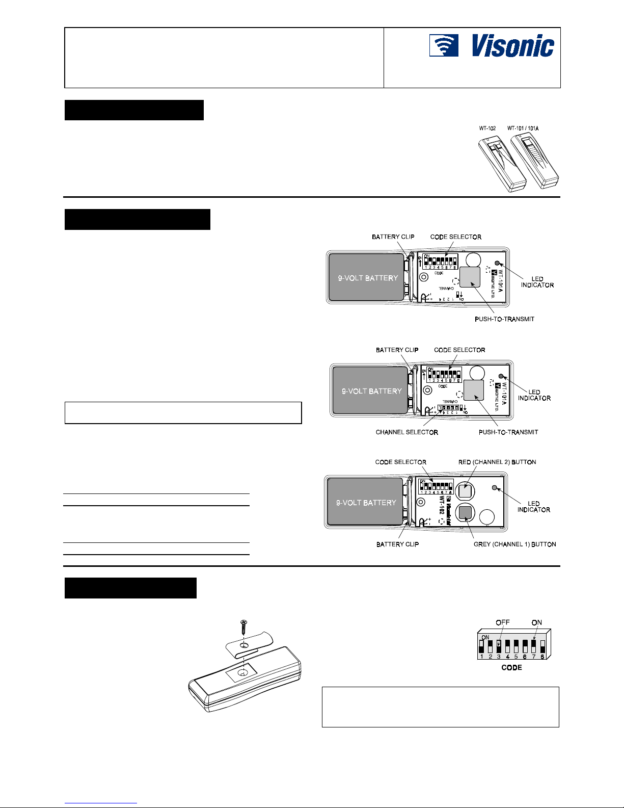
Model WT-101 (see Fig. 1): This model activates the receiver's
"channel 1" output relay.
Model WT-101A (see Fig. 2): This model can be programmed to
activate any one of the 4 output relays in the receiver - from
"channel 1" to "channel 4".
FCC ID: GSAWT101A; CANADA: 1467 202 271A
Model WT-102 (see Fig. 3): The gray button activates the
receiver's "channel 1" output relay, and the red button activates
"channel 2" output relay.
FCC ID: GSAWT102A; CANADA: 6515 1467 K694
Figure 1. WT-101, Cover Removed
Figure 2. WT-101A, Cover Removed
Figure 3. WT-102, Cover Removed
3333. INSTALLATION
. INSTALLATION. INSTALLATION
. INSTALLATION
3.1 Connecting the Battery
A. Remove the screw and the
belt clip at the back of the
unit (see Figure 4).
B. Position the transmitter with
the front side up and detach
the front cover from the
base.
C. Install the battery clip onto
the 9-Volt battery. Position
the battery as shown in
Figures 1, 2 and 3.
Figure 4. Screw and Belt Clip
3.2 Selecting the System Code
All models have an 8-position DIP
switch (marked 1 - 8, see Fig. 5). Each
switch may be set to ON or OFF,
creating a unique digital system code.
Use a ball-point pen to set each of the
switches to match the code setting of
the target receiver.
Figure 5. Code Selector
CAUTION: The code combination 2, 4, 5, 6, 7 ON and 1, 3, 8
OFF (as shown in Figure 5) is a factory test code that should be
avoided. Also do not select "easy" codes such as all keys ON,
all keys OFF or alternating ON/OFF settings.
Page 2
2 DE2031
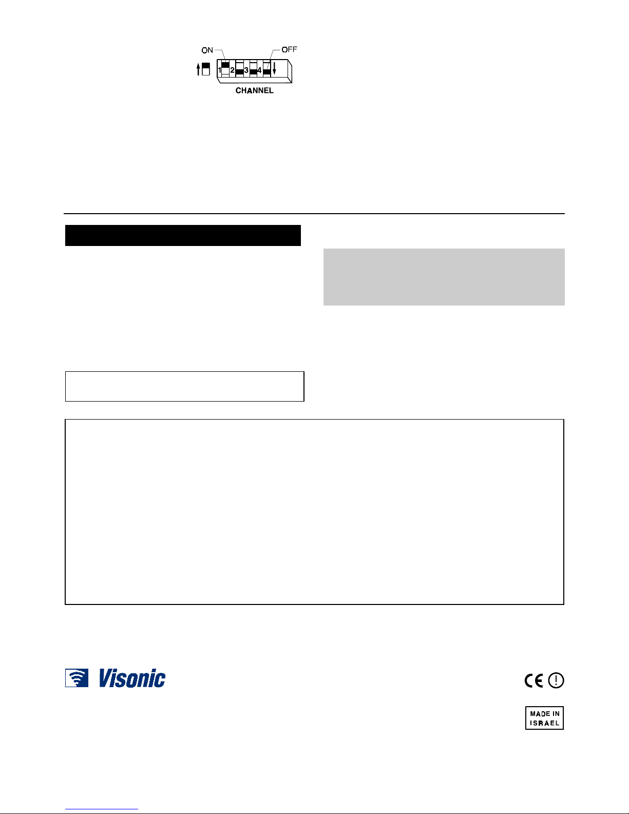
3.3 Setting the Channel Code (WT-101A only)
The WT-101A transmitter is
equipped with a 4-position
DIP-switch marked CHANNEL
(Fig. 6) that serves as a channel
selector. By means of this
switch, the transmitter can be
programmed to activate one of 4
outputs at the receiver.
Figure 6. Channel Selector
This feature is important for zoning purposes – activating different
alarm zones of a control panel via a multi-output receiver. The
channel data transmitted by the WT-101A is selected by setting
the switch with the desired channel number to ON. Use a ball
point pen to set the channel selector as required.
3.4 Assembly and Testing
A. Carefully position the front cover in place, press it against the
base and turn the unit with its back up. Position the belt clip
as shown in Figure 4 and re-insert the screw.
B. Stand 3 meters (10 feet) away from the receiver and operate
the transmitter.
C. Verify that the transmitter LED lights, indicating good battery
condition.
D. Observe that the receiver LED lights, indicating detection of
the transmitted RF signal.
E. Make sure that the expected end result is obtained:
WT-101: Verify activation of the "channel 1" output relay at the
receiver.
WT-101A: Verify activation of the desired output relay at the
receiver, according to the channel selected.
WT-102: Verify that the transmitter gray pushbutton activates
the receiver's "channel 1" output relay and that the red
pushbutton activates the receiver's "channel 2" output relay.
F. Operate the transmitter at various locations within the
reception range to determine "dead" spots, where
transmission may be blocked.
4444.
. .
. MISCELLANEOUS COMMENTS
MISCELLANEOUS COMMENTSMISCELLANEOUS COMMENTS
MISCELLANEOUS COMMENTS
4.1 Product Limitations
Visonic Ltd. wireless systems are very reliable and are tested to
high standards. However, due to their low transmitting power and
limited range (required by FCC and other regulatory authorities),
there are some limitations to be considered:
A. Receivers may be blocked by radio signals occurring on or near
their operating frequencies, regardless of the code selected.
B. A receiver can only respond to one transmitter signal at a time.
C. Wireless equipment must be tested regularly to reveal sources
of interference and to protect against faults.
4.2 Compliance with Standards
This device complies with the essential requirements and provisions
of Directive 1999/5/EC of the European Parliament and of the Council
of 9 March 1999 on radio and telecommunications terminal equipment.
The 315 MHz model of this device complies with Part 15 of the
FCC Rules and RSS-210 of Industry and Science Canada.
Operation is subject to the following two conditions: (1) This
device may not cause harmful interference, and (2) this device
must accept any interference that may be received, including
interference that may cause undesired operation.
The user is cautioned that changes or modifications to the
unit, not expressly approved by Visonic Ltd., could void the
user's FCC authority to operate the equipment.
4.3 Frequency Allocations for Wireless
Devices in European (EU) Countries
• 433.92 MHz has no restriction in any EU member state.
• 418 MHz is allowed in the UK only.
• 315 MHz is not allowed in any EU member state
WARRANTY
WARRANTYWARRANTY
WARRANTY
Visonic Ltd. and/or its subsidiaries and its affiliates ("the Manufacturer") warrants its
products hereinafter referred to as "the Product" or "Products" to be in conformance with
its own plans and specifications and to be free of defects in materials and workmanship
under normal use and service for a period of twelve months from the date of shipment by
the Manufacturer. The Manufacturer's obligations shall be limited within the warranty
period, at its option, to repair or replace the product or any part thereof. The Manufacturer
shall not be responsible for dismantling and/or reinstallation charges. To exercise the
warranty the product must be returned to the Manufacturer freight prepaid and insured.
This warranty does not apply in the following cases: improper installation, misuse,
failure to follow installation and operating instructions, alteration, abuse, accident or
tampering, and repair by anyone other than the Manufacturer.
This warranty is exclusive and expressly in lieu of all other warranties, obligations or
liabilities, whether written, oral, express or implied, including any warranty of
merchantability or fitness for a particular purpose, or otherwise. In no case shall the
Manufacturer be liable to anyone for any consequential or incidental damages for breach
of this warranty or any other warranties whatsoever, as aforesaid.
This warranty shall not be modified, varied or extended, and the Manufacturer does not
authorize any person to act on its behalf in the modification, variation or extension of this
warranty. This warranty shall apply to the Product only. All products, accessories or
attachments of others used in conjunction with the Product, including batteries, shall be
covered solely by their own warranty, if any. The Manufacturer shall not be liable for any
damage or loss whatsoever, whether directly, indirectly, incidentally, consequentially or
otherwise, caused by the malfunction of the Product due to products, accessories, or
attachments of others, including batteries, used in conjunction with the Products.
The Manufacturer does not represent that its Product may not be compromised and/or
circumvented, or that the Product will prevent any death, personal and/or bodily injury
and/or damage to property resulting from burglary, robbery, fire or otherwise, or that the
Product will in all cases provide adequate warning or protection. User understands that a
properly installed and maintained alarm may only reduce the risk of events such as
burglary, robbery, and fire without warning, but it is not insurance or a guarantee that such
will not occur or that there will be no death, personal damage and/or damage to property
as a result.
The Manufacturer shall have no liability for any death, personal and/or bodily injury
and/or damage to property or other loss whether direct, indirect, incidental,
consequential or otherwise, based on a claim that the Product failed to function.
However, if the Manufacturer is held liable, whether directly or indirectly, for any loss or
damage arising under this limited warranty or otherwise, regardless of cause or origin, the
Manufacturer's maximum liability shall not in any case exceed the purchase price of the
Product, which shall be fixed as liquidated damages and not as a penalty, and shall be the
complete and exclusive remedy against the Manufacturer.
Warning: The user should follow the installation and operation instructions and among
other things test the Product and the whole system at least once a week. For various
reasons, including, but not limited to, changes in environmental conditions, electric or
electronic disruptions and tampering, the Product may not perform as expected. The user
is advised to take all necessary precautions for his /her safety and the protection of
his/her property.
6/91
VISONIC LTD (ISRAEL): P.O.B 22020 TEL-AVIV 61220 ISRAEL. PHONE: (972-3) 645-6789, FAX: (972-3) 645-6788
VISONIC INC. (U.S.A.): 10 NORTHWOOD DRIVE, BLOOMFIELD CT. 06002-1911. PHONE: (860) 243-0833, (800) 223-0020 FAX: (860) 242-8094
VISONIC LTD. (UK): FRASER ROAD, PRIORY BUSINESS PARK, BEDFO RD MK44 3WH. PHONE: (0870) 730-0800 FAX: (0870) 730-0801
INTERNET:
www.visonic.com
VISONIC LTD. 2001 WT-101/102 DE2031- (REV. 5, 7/01)
 Loading...