

Page 1
DE2001 1
WT
WTWT
WT-100
-100-100
-100, WT
, WT, WT
, WT-100
-100-100
-100AAAA
Universal Wireless Transmitters
Installation Instructions
1111. INTRODUCTION
. INTRODUCTION. INTRODUCTION
. INTRODUCTION
The WT-100 and WT-100A are general purpose, battery powered single-input
transmitters for use with Normally Open (N.O.) and Normally Closed (N.C.) sensors
and inertial vibration detectors.
A reed switch built into both units can be used with a magnet (not supplied) to protect a
door or a window. An on-board tamper switch triggers a tamper alert (Channel 2) if the
front cover is removed from the base.
A special timing circuit saves the 9-volt battery power by limiting the transmitting time.
When the WT-100 is triggered, it transmits for about 2 seconds, then inhibits itself for
approximately one minute. If an input remains disturbed, the WT-100 will keep
transmitting signals for a 2-second duration each minute, until the input reverts to the
undisturbed state. The WT-100A is a single-shot (non-repeating) model that transmits
only once upon each input trigger.
The LED lights during the transmission period. A special circuit continuously monitors
the battery voltage. If this drops below about 7.5 Volts, the transmitter automatically
transmits a low battery alert signal for 1-2 seconds, to activate a buzzer in the target
receiver. Low battery signals are repeated at one-minute intervals for a few days,
depending on the remaining amount of battery energy. The LED lights during each
transmission, identifying the unit transmitting the low battery signal.
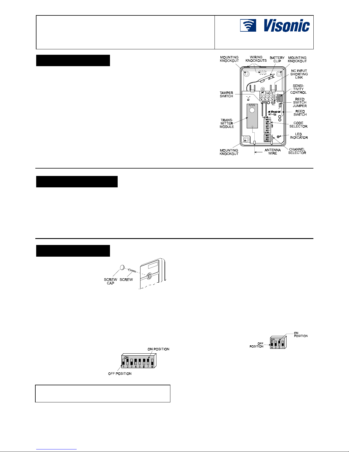
Figure 1. WT-100 and WT-100A
2222. SPECIFICATIONS
. SPECIFICATIONS. SPECIFICATIONS
. SPECIFICATIONS
Frequency (MHz): 315, 404, 418, 433.92 or other frequencies
according to local requirements
System Code: 8-bit, 256 combinations, pulse width modulation
Channel Codes: 4 codes, DIP-switch selectable
Transmission Cycle: 2 seconds ON, 1 minute OFF, indicated by
LED.
Input Circuit: N.C. / N.O. (N.C. input must be shorted by the N.C.
jumper if not used).
Input Response: Adjustable, 5 to 30 ms
Power Supply: 9 VDC Alkaline or Lithium battery
Current Consumption: 10 µA standby, 10 mA in operation
Battery Supervision: Automatic transmission of low battery
alert code, which activates a buzzer in the receiver.
Compliance with Standards: Meets FCC Part 15, MPT 1349
and Directive 1999/5/EC.
Operating Temperature: 0°C to 49°C (32°F to 120°F).
Dimensions: 110 x 63 x 25 mm (4-5/16 x 2-1/2 x 1 in.).
Weight: 68 g (2.4 oz)
3333. INSTALLATION
. INSTALLATION. INSTALLATION
. INSTALLATION
3.1 Mounting
Open the case by removing
the screw from the front cover.
Mount the base with the
printed circuit board in the
selected location, using the
mounting knockouts.
Figure 2. Front Cover Removal
Be sure to mount the unit with the antenna wire hanging down.
Route the wiring through any wiring knockout in the base.
3.2 System Code Selection
!
The on-board CODE selector consists of an 8-position DIP switch
with keys marked from 1 to 8 (see Fig. 3). Each key is set to
either ON or OFF to create a unique digital code (256 possible
combinations). This code serves as a system code or a
password between the transmitter and the target receiver.
Select the desired system code
by shifting the keys with a ballpoint pen or a small screwdriver. All wireless units used in
the system and the target
receiver must be programmed
with the same digital code.
Figure 3. Code Selector
Caution: The factory test code combination 2, 4, 5, 6, 7 ON /
1, 3, 8 OFF must not be used. Also avoid codes which are often
used: all keys ON, all keys OFF or alternating ON/OFF settings.
3.3 Channel Selection
!
Each transmitter can be set to transmit one of four different
"channel codes". The channel code is added to the system code
to activate a specific output in a multi-output receiver. Channel
codes are very useful for zoning purposes (activating various
types of zones of an alarm control panel).
The channel code selector consists of a 4-position DIP switch,
with keys marked from 1 to 4. The code is selected by switching
the corresponding key(s) to ON. You may select more than one
channel code for simultaneous activation of several channel
outputs at the receiver.
Note: Channel 2 code is transmitted automatically as a tamper
alert whenever the front cover is removed.
Setting all four-channel keys to
OFF will activate the buzzer at
the receiver (same as low
battery alert) and none of the
receiver's channel outputs.
Figure 4. Selecting Channel 2
3.4 Input Sensitivity Adjustment
Input sensitivity for vibration detectors is adjusted with the SENS.
potentiometer. The sensitivity is at maximum (response time
about 5 ms) with the control knob rotated fully towards [+] and at
minimum (response time about 30 ms) with the control knob
rotated fully towards [–]. If you are not using a vibration detector,
set the control fully towards [–].
Page 2
2 DE2001
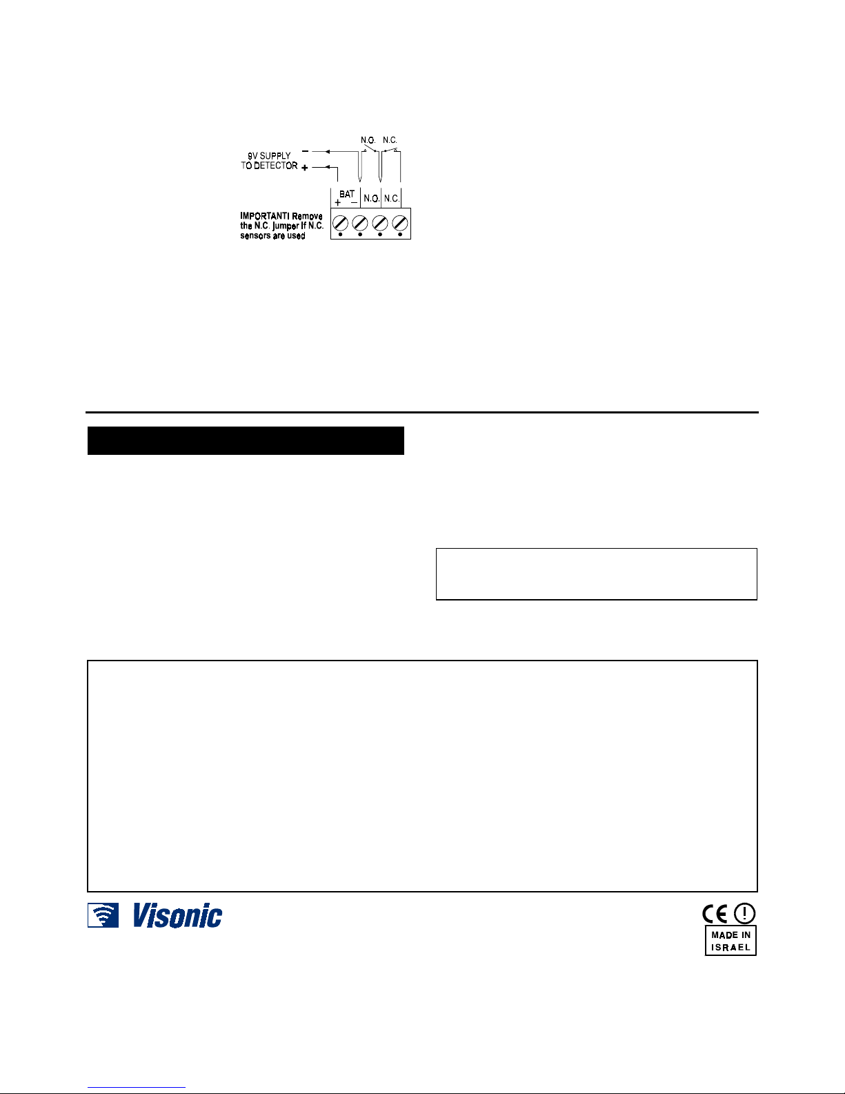
3.5 Wiring
!
Normally closed sensors and inertial vibration detectors are wired
in series between the terminals marked N.C.
Note: If the N.C. input is not used, it must be shorted by installing
a jumper on the N.C. header below the terminal block (Fig. 1).
Normally open alarm contacts should be wired in parallel with the
terminals marked N.O..
Visonic Ltd. low current
SRN-2000C/PC series PIR
detectors may be powered
from the 1st (+) and 2nd (–)
terminals from the left.
When using the same
battery for the transmitter
and the PIR detector,
low-battery supervision is
obtained for both units.
Figure 5. Terminal Block Wiring
To use the reed switch, remove the reed switch jumper "J1"
(located near the reed switch).
3.6 Battery Installation
Note: Before installing the battery, use some masking tape to
temporarily keep the tamper switch lever down. This will prevent
the unit from continuously transmitting a tamper alert while the
front cover is removed for testing.
The units are powered by a 9-volt alkaline or lithium battery.
For proper operation, use only an alkaline or lithium battery.
Snap the battery clip onto the battery terminals and put the
battery in place (above the PC board).
3.7 Testing
!
A. Select the desired system code as instructed in Section 3.2.
B. Select a channel code as instructed in Section 3.3.
C. Activate the sensor connected to the transmitter input.
Note: If a vibration detector is used, adjust the sensitivity with
the SENSE control (see Section 3.4).
D. Verify that the transmitter LED lights during transmission.
E. WT-100: Leave the sensor input disturbed for several
minutes. Verify that the unit repeats the transmission for
approximately 2 seconds each minute.
WT-100A: As with WT-100, but verify transmission only once.
F. Check whether the receiver’s LED lights steadily, indicating
good detection of the RF signal.
G. Verify that the receiver's corresponding relay energizes while
receiving a signal.
H. Restore the transmitter's input to its undisturbed state, set all
4 channel switches to OFF and initiate a transmission. This
should cause the low-battery alert buzzer at the receiver to
sound (provided that a buzzer is connected to the receiver).
I. Re-select the desired channel code with the four channel
switches.
J. Remove the masking tape used to hold down the tamper
switch lever. The transmission triggered by the tamper switch
should cause channel 2 relay of the receiver to energize.
K. Carefully position the front cover hole over the LED. Secure
the front cover to the base with the screw and insert the
plastic cap into the hole (Fig. 2).
4444. MISCELLANEOUS COMMENTS
. MISCELLANEOUS COMMENTS. MISCELLANEOUS COMMENTS
. MISCELLANEOUS COMMENTS
4.1 Product Limitations
Visonic Ltd. wireless systems are very reliable and are tested to
high standards. However, due to low transmitting power and
limited range (required by FCC and other regulatory authorities),
there are some limitations to be considered:
A. A receiver may be blocked by radio signals sent on or near its
operating frequency, regardless of the digital code used.
B. A receiver responds to one transmitted signal at a time.
C. Wireless equipment should be tested regularly to determine
whether there are sources of interference and to protect
against faults.
4.2 Compliance with Standards
The 315 MHz model of this device contains RF module RFT-1A,
which complies with Part 15 of the FCC Rules and RSS-210 of
Industry and Science Canada. Operation is subject to these two
conditions: (1) This device may not cause harmful interference,
and (2) this device must accept any interference received,
including interference that may cause undesirable operation.
The user is cautioned that changes or modifications to the
unit, not expressly approved by Visonic Ltd., could void the
user's FCC or other authority to operate the equipment.
This device complies with the essential requirements and provisions
of Directive 1999/5/EC of the European Parliament and of the Council
of 9 March 1999 on radio and telecommunications terminal
equipment.
Frequency Allocations for Wireless Devices in European Countries:
• 433.92 MHz has no restriction in any EU member state.
• 418 MHz is allowed in the UK only.
• 315 MHz is not allowed in any EU member state.
WARRANTY
WARRANTYWARRANTY
WARRANTY
Visonic Ltd. and/or its subsidiaries and its affiliates ("the Manufacturer") warrants its
products hereinafter referred to as "the Product" or "Products" to be in conformance with
its own plans and specifications and to be free of defects in materials and workmanship
under normal use and service for a period of twelve months from the date of shipment by
the Manufacturer. The Manufacturer's obligations shall be limited within the warranty
period, at its option, to repair or replace the product or any part thereof. The Manufacturer
shall not be responsible for dismantling and/or reinstallation charges. To exercise the
warranty the product must be returned to the Manufacturer freight prepaid and insured.
This warranty does not apply in the following cases: improper installation, misuse,
failure to follow installation and operating instructions, alteration, abuse, accident or
tampering, and repair by anyone other than the Manufacturer.
This warranty is exclusive and expressly in lieu of all other warranties, obligations or
liabilities, whether written, oral, express or implied, including any warranty of
merchantability or fitness for a particular purpose, or otherwise. In no case shall the
Manufacturer be liable to anyone for any consequential or incidental damages for breach
of this warranty or any other warranties whatsoever, as aforesaid.
This warranty shall not be modified, varied or extended, and the Manufacturer does not
authorize any person to act on its behalf in the modification, variation or extension of this
warranty. This warranty shall apply to the Product only. All products, accessories or
attachments of others used in conjunction with the Product, including batteries, shall be
covered solely by their own warranty, if any. The Manufacturer shall not be liable for any
damage or loss whatsoever, whether directly, indirectly, incidentally, consequentially or
otherwise, caused by the malfunction of the Product due to products, accessories, or
attachments of others, including batteries, used in conjunction with the Products.
The Manufacturer does not represent that its Product may not be compromised and/or
circumvented, or that the Product will prevent any death, personal and/or bodily injury
and/or damage to property resulting from burglary, robbery, fire or otherwise, or that the
Product will in all cases provide adequate warning or protection. User understands that a
properly installed and maintained alarm may only reduce the risk of events such as
burglary, robbery, and fire without warning, but it is not insurance or a guarantee that such
will not occur or that there will be no death, personal damage and/or damage to property
as a result.
The Manufacturer shall have no liability for any death, personal and/or bodily injury
and/or damage to property or other loss whether direct, indirect, incidental,
consequential or otherwise, based on a claim that the Product failed to function.
However, if the Manufacturer is held liable, whether directly or indirectly, for any loss or
damage arising under this limited warranty or otherwise, regardless of cause or origin, the
Manufacturer's maximum liability shall not in any case exceed the purchase price of the
Product, which shall be fixed as liquidated damages and not as a penalty, and shall be the
complete and exclusive remedy against the Manufacturer.
Warning: The user should follow the installation and operation instructions and among
other things test the Product and the whole system at least once a week. For various
reasons, including, but not limited to, changes in environmental conditions, electric or
electronic disruptions and tampering, the Product may not perform as expected. The user
is advised to take all necessary precautions for his /her safety and the protection of
his/her property.
6/91
VISONIC LTD. (ISRAEL): P.O.B 22020 TEL-AVIV 61220 ISRAEL. PHONE: (972-3) 645-6789, FAX: (972-3) 645-6788
VISONIC INC. (U.S.A.): 10 NORTHWOOD DRIVE, BLOOMFIELD CT. 06002-1911. PHONE: (860) 243-0833, (800) 223-0020 FAX: (860) 242-8094
VISONIC LTD. (UK): FRASER ROAD, PRIORY BUSINESS PARK, BEDFO RD MK44 3WH. PHONE: (0870) 730-0800 FAX: (0870) 730-0801
INTERNET:
www.visonic.com
© VISONIC LTD. 2001 WT-100 D-2001-0 NEW: DE2001- (REV. 5, 3/01)
 Loading...