

Page 1
DE4040 1
WRP
WRPWRP
WRP-600
-600-600
-600
Microprocessor-Controlled Wireless Repeater
Installation Instructions
1111. INTRODUCTION
. INTRODUCTION. INTRODUCTION
. INTRODUCTION
The WRP-600 is a microprocessor controlled wireless repeater,
designed to relay digital data between wireless transmitters and a
target receiver. Repeater links are required when the target
receiver is beyond the range of at least some of the wireless
transmitters and is therefore incapable of receiving transmissions
directly (refer to Figure 1).
As a communication range extender for all Visonic Ltd. low-power
wireless transmitters, this repeater is compatible with the standard
line (WT/WR series) that uses 12-bit DIP-switch programmable
codes and with the new "PowerCode" family (MCT/MCR series)
that uses 16,000,000 self-learning codes. A WRP-600 repeater
can simultaneously serve both 12-bit and PowerCode
networks that coexist in the same area (but is not compatible
with CodeSecure™ equipment).
If the distance between the transmitters and the target receiver is
too large to be covered with one repeater, several auxiliary
repeaters may be added along the communication path. This
way, a multi-level network is created (see Figure 2).
Up to 16 auxiliary repeaters can be interposed between the
farthest group of transmitters and the target receiver.
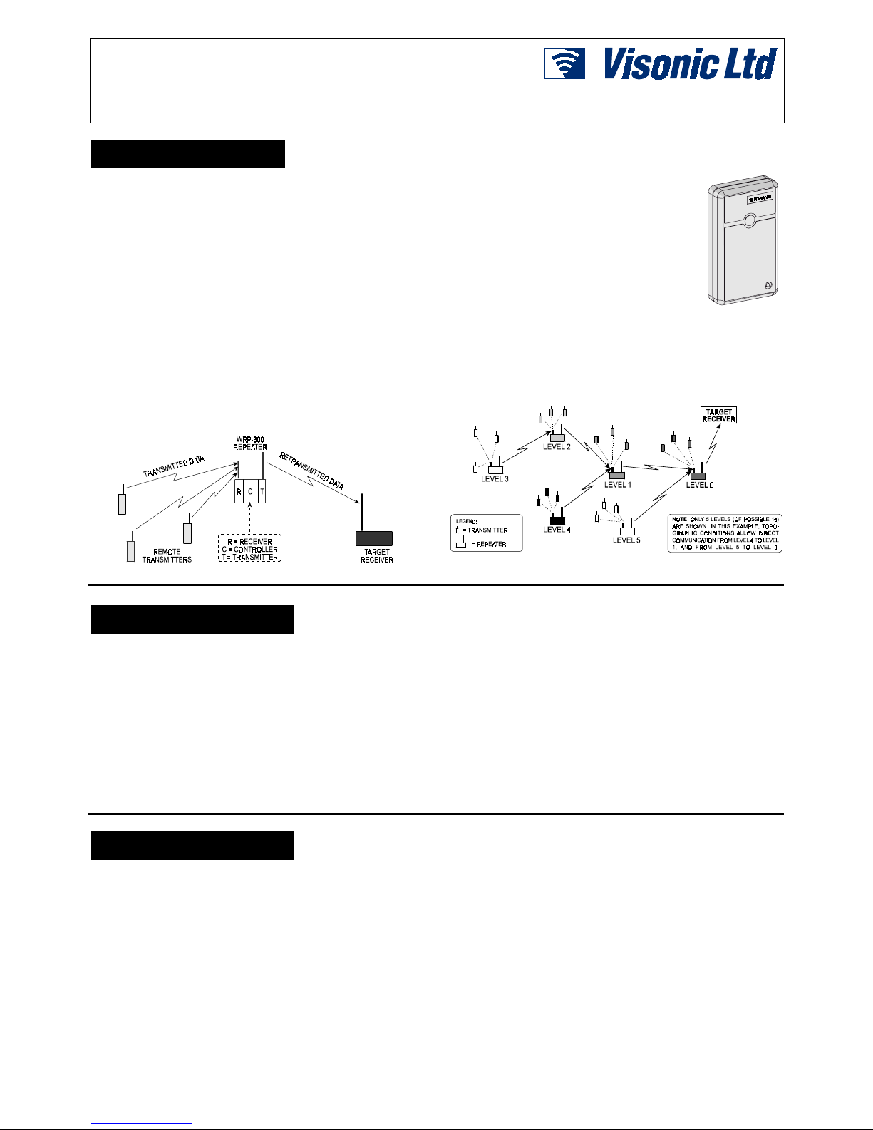
Figure 1. Single-Level Repeater Configuration
Each repeater must be assigned a correct
LEVEL TAG for the system to operate properly.
The repeater closest to the target receiver is at
LEVEL 0, and level numbers go up with each
added repeater, up to LEVEL 15.
A receiver module, a transmitter module and a
controller motherboard are the building blocks
of the WRP-600. All 3 units are packaged in
a small-size, easy-to-install plastic housing.
Both
receiver and transmitter use short, downhanging wire antennas. The WRP-600 repeater is powered by 13
to 20 VDC supply or 11-16 VAC. A 9-Volt nickel-cadmium
rechargeable battery provides backup in case of mains power
failure.
The battery is recharged by a built-in charger. A fully charged 110
mA/h battery will provide about 5 hours of emergency operation
at 1:1 receive/transmit ratio.
Figure 2. Multi-Level Repeater Configuration
2222. SPECIFICATIONS
. SPECIFICATIONS. SPECIFICATIONS
. SPECIFICATIONS
Operating Frequencies: Any one of 315, 404, 418, 433.9 MHz,
or other frequencies in accordance with local requirements.
Receiver Type: Super-regenerative.
Modulation Type: 100% ASK.
System Codes (in 12-bit systems): 8-bit digital word, 256
combinations, pulse width modulation.
PowerCode ID: One of 16,000,000 possible 24-bit codes
Power Input Ranges: 13 - 20 VDC, or 11 - 16 VAC, 100 mA min.
Backup Battery: 9 V (8.4 V), 110 mA/h rechargeable Ni-Cd type.
Current Consumption @ 14 VDC:
• With Rechargeable Battery: 17.5 mA.
• Without Battery: 5.5 mA.
Note: There is no change in current consumption between the
receive and transmit modes.
Battery Backup Duration: Approx. 5 hours with a fully charged
110 mA/h Ni-Cd battery and 1:1 standby/transmit ratio.
LED indicator: Lights during transmission.
Compliance with Standards: Meets FCC Part 15, ETS 300-220
and MPT 1340. The 418 & 433.92 MHz units comply with
European Council Directive EMC 89/336/EEC & 92/31/EEC, and
bear the CE mark and certification.
Operating Temperature: 0°C to 49°C (32°
F to 120° F).
Dimensions (H
x W x
D):
110 x 63 x 25 mm (4-5/16 x 2-1/2 x 1 in.).
Weight: 73 g (2.6 oz).
3333. FUNCTIONALITY
. FUNCTIONALITY. FUNCTIONALITY
. FUNCTIONALITY
3.1 Interfacing with 12-Bit Systems
In 12-bit systems that do not employ W RP-600 repeaters, 8 bits
are used for the system code, and all transmitters as well as the
target receiver are set to the same 8-bit code.
With WRP-600 repeaters in use, it is sometimes required to
determine which transmitter will take advantage of the repeater
and which transmitter will send its data directly to the target
receiver without repeater intervention.
To make this possible, all transmitters intended to send their
signals via the WRP-600 must transmit a system code combination in which the 8th (most significant) bit is OFF.
The repeater programmed for operation at LEVEL 0 (the one
closest to the target receiver) rejects any system code in which
the 8th bit is ON. On the other hand, it accepts any system code
in which the 8th bit is OFF, but inverts the 8th bit upon retransmission (the 8th bit in the retransmitted code becomes ON).
In order to receive the retransmitted code, the target receiver
should be set to the same code as that retransmitted by LEVEL 0
repeater (with the 8th bit ON).
Transmitters deployed in close proximity to the target receiver
must be set to the same code as that of the receiver. Since the
8th bit of their code is ON, their signals will be rejected by any
repeater but not by the target receiver.
Page 2
2 DE4040
Repeaters programmed to operate at any level above LEVEL 0
do not invert the 8th bit - they retransmit the received code "as is".
In multi-repeater networks, each repeater adds its own 4-bit
LEVEL TAG to any incoming code, and the expanded data string
is retransmitted. The level tag is important for inter-repeater communications, since it permits each repeater to distinguish
between original and retransmitted codes, and to determine
whether the signal is coming from a higher or a lower level (see
Section 4). However, the last repeater in the chain (the one at
LEVEL 0) retransmits the code without adding any level tag.
3.2 Interfacing with PowerCode
Systems
PowerCode transmitters use 24-bit ID codes, randomly selected
in the factory from over 16 million available combinations. When
a PowerCode transmitter is keyed on, its code is received by the
repeater and retransmitted to the target receiver.
Each WRP-600 repeater has its own unique, factory determined
24-bit PowerCode ID. However, this ID code is only utilized for
reporting the repeater's own service alerts (see Para. 3.5).
When a WRP-600 repeater is placed into service in a PowerCode
system, its PowerCode identity must be "revived" (see Para. 6.3
for detailed procedure). If this isn't done, the repeater will
retransmit PowerCode messages but will not send out its own
service alerts.
3.3 Single Repeater Links
A. What is "LEVEL 0" ?
In many cases, a single repeater is enough to bridge the communication gap between the deployed transmitters and the target
receiver. In a single repeater setup, all 4 levers of the on-board
DIP switch level selector must be set to OFF - i.e. LEVEL 0.
Multi-repeater networks are dealt with in Para. 3.4.
B. LEVEL 0 in 12-bit Systems
In 12-bit systems, LEVEL 0 means that the repeater will retransmit any received message, without adding a LEVEL TAG
(the level tag is only significant in multi-repeater networks).
At LEVEL 0, the repeater will retransmit a received message with
inversion of the 8th bit of the system code - ON instead of OFF.
This feature is important for systems in which repeater-dependent
and repeater-independent transmitters operate together.
C. LEVEL 0 in PowerCode Systems
In PowerCode systems, a repeater at LEVEL 0 will simply retransmit any received message, without adding its own level tag
(which is only significant in multi-repeater networks - see Para.
3.4). Refer to Para. 4.1 for detailed communication routine at
LEVEL 0.
3.4 Multi Repeater Network
A. The Multi-Level Concept
An auxiliary repeater positioned along the communication path
retransmits data received from any higher level repeater to any
lower level repeater, but may also be used to retransmit data
received from transmitters deployed near it, in its local coverage
area (see Figure 2).
Data flows from the highest level repeater through intermediate
repeater links to the lowest level repeater (LEVEL 0) and finally
reaches the target receiver.
By virtue of differences in message format and the level tag (see
Figure 3), each repeater in a multi-level network can distinguish
between signals coming from nearby transmitters and signals
coming from higher or lower level repeaters. The repeater's
response is based on this distinction.
At all levels except for level 0, messages are retained in the
repeater's memory until they are taken care of by the next
repeater. Detection of the same message being forwarded further
down the communication path serves as an acknowledgement for
the higher level repeaters. Upon detection of a "downgoing"
message, the higher level repeater stops its attempts to forward
the specific message and deletes the message from its memory.
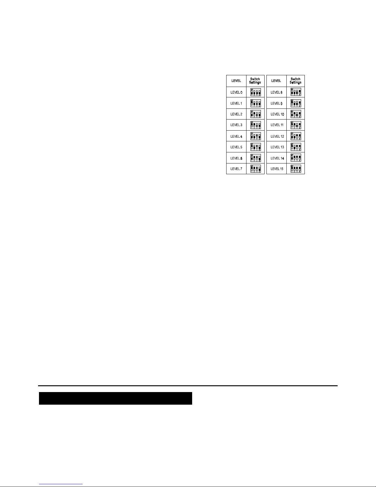
B. Selecting Level Tags
The 4-position DIP switch on the repeater's PCB allows the
installer to select the desired level by setting its 4 switch levers to
16 different combinations, as shown in Figure 3.
All repeaters leave the factory with the 4 level selection switches
set to OFF (Level 0 is selected).
Figure 3. Selecting the LEVEL Number
3.5 Service Alerts
A. Service Codes in 12-bit Systems
Visonic Ltd. 12-bit transmitters use the 4-bit CHANNEL code (bits
9 -12) to determine which output channel (from possible 16) will
be activated by the receiver. Channels 0 and 2 are reserved for
reporting low battery and tamper alerts, so only 14 output
channels are in fact available.
When operating in a 12-bit system, the repeater must be "taught"
the system code in order to be able to send out service alerts
(see Para. 6.2 for details). Having learned the system code, the
repeater can send out two types of service alert:
AC FAILURE - The CHANNEL 0 code informs of a power supply
problem in the repeater.
TAMPER - The CHANNEL 2 code informs that the repeater is
being tampered with.
Note: Since in a 12-bit system the receiver does not indicate
which repeater (or transmitter) sent the service message, each
repeater or transmitter has to be inspected until the faulty unit is
found.
B. Service Codes in PowerCode Systems
Each WRP-600 unit has its own 24-bit ID just like any other
transmitter in the system. When operating in a PowerCode
system, the repeater's ID must be "revived" in order to be able to
send out service alerts (see Para. 6.3). With the repeater's ID
active, the repeater can generate 3 kinds of service message:
• Tamper alert
• AC failure warning
• Once-per-hour test report
If the TAMPER or AC FAILURE states last long, the respective
codes will be sent out again with each test report.
When the repeater transmits a service message in a PowerCode
system, the repeater ID is automatically included in the outgoing
message to identify the specific repeater to the receiver. Service
personnel therefore know exactly where the problem lies.
4444. THE COMMUNICATION PROCESS
. THE COMMUNICATION PROCESS. THE COMMUNICATION PROCESS
. THE COMMUNICATION PROCESS
Once the repeater is powered up, its receiver section stands by for
incoming messages and its transmitter section is inactive.
4.1 Single Repeater Routine
A. The repeater checks received messages sent by transmitters
deployed in its coverage area. Messages are rejected in the
following cases:
• In 12-bit systems - if they are incorrectly formatted and/or if
the 8th bit is set to ON.
• In PowerCode systems - if they do not include the proper
24-bit ID format and/or do not pass the checksum test.
B. Valid messages are saved in the message buffer, for
retransmission as soon as transmission is allowed.
Page 3

DE4040 3
Note: Before transmission, the repeater checks whether the RF
channel is free - it is programmed to transmit on a free channel
only. However, in case of continuous interference or uninterrupted stream of incoming messages, a 30 second timeout will
cause the repeater to stop receiving, retransmit the contents of
its message buffer and revert to the receive mode.
C. Once transmission is allowed, the repeater retransmits all the
messages stored in its buffer, "last in, first out". Each
message is retransmitted repeatedly for two seconds.
D. A message which has already been retransmitted to the
receiver is deleted from the repeater's transmission queue.
4.2 Multi-Repeater Routine
In multi-level networks, an intermediate level repeater must be
located within communication range with at least one higher level
repeater (for relaying messages) and at least one lower level
repeater (for
receiving acknowledgements). A message recognized
as coming from a higher level repeater or a local transmitter will be
accepted and retransmitted. A message received from a higher
level repeater or from a local transmitter, retransmitted and then
received again from a lower level repeater is understood to be
forwarded further down the chain of repeaters. Transmission of the
same message serves as an acknowledge signal for the higher
level repeater, which will delete the message from its
retransmission list.
A. Repeaters at all levels collect and save messages from
transmitters deployed in their respective coverage areas and
also from repeaters in the next higher level. Messages are
rejected in the following cases:
• In 12-bit systems - if they are incorrectly formatted and/or if
the 8th bit is ON.
• In PowerCode systems - if they do not include the proper
24-bit ID format and/or do not pass the checksum test.
B. Valid messages are saved in the message buffer, for
retransmission as soon as transmission is allowed.
Note: Before retransmission, the repeater checks whether the
RF channel is free - it is programmed to transmit on a free
channel only. However, In case of continuous interference or
uninterrupted stream of incoming messages, a 30 second timeout will cause the repeater to stop receiving, retransmit the
contents of its message buffer and revert to the receive mode.
C. Once transmission is allowed, each repeater retransmits all
messages stored in its buffer, using the "last in, first out"
method.
Note: To prevent collision of messages transmitted by repeaters
at various levels, a different
REPEAT INTERVAL
(inter- message
interval) is programmed for each level. This interval is
determined automatically as a function of the repeater's LEVEL.
D. Upon retransmission, messages are picked up by a lower level
repeater for further transmission towards the target receiver.
Reception of the lower level retransmission by the upper level
repeater serves as an acknowledgement which stops further
repetitions of the same message by the upper level repeater.
E. Once a certain repeater (Level 1 and up) receives a message
from a lower level repeater and identifies it as one it had
previously handled, it will remove the message from its
message buffer.
F. Without acknowledgement from a lower level repeater, the
higher level repeater will transmit the message again after the
"repeat interval" (which depends on the repeater's level). A
maximum of 8 repetitions is allowed, before the repeater "gives
up" and passes on to the next message.
5555. INSTALLATION
. INSTALLATION. INSTALLATION
. INSTALLATION
5.1 Selecting the Repeater's Location
A. In a single repeater setup, install the repeater where good
communication is assured with the target receiver and with
the transmitters deployed in the repeater's coverage area. In
multi-repeater networks, good communication must be assured
with the deployed transmitters and the repeaters at the next
higher and next lower levels.
B. Do not stretch the coverage area to its utmost limit, because
this can disrupt your communication link. It is better to add
repeaters than to rely on marginal reception.
C. Mount the repeater as high
as possible above the floor
and well away from metal
chimneys, large metal
cabinets, metal doors and
reinforced concrete walls, all
of which may reduce the
communication range.
Figure 4. Front cover
Assembly
5.2 Mounting Procedure
A. Remove the screw and the front cover (see Fig. 4). The round
plastic cap is supplied separately in a small nylon bag.
B. Mount the base (equipped with the printed circuit board) in the
selected location, using the mounting knockouts (see Fig. 5).
C. Make sure the antenna wires hang down vertically (do not
allow them to bend close together). Tape them to the wall if
necessary.
D. Snap the battery clip onto the battery and place the battery in
the open space above the P.C. board.
E. Plug the AC adapter into an uninterruptible mains outlet and
connect the low voltage wires to the repeater's 14 V terminals.
Note: Any standard DC power supply or AC step-down
transformer would do, if it delivers 12V AC or DC / 100 mA.
(Refer to Section 2 for input voltage limits)
Figure 5. WRP-600, Cover Removed
6666. PROGRAMMING
. PROGRAMMING. PROGRAMMING
. PROGRAMMING
6.1 Level Tagging
The first programming step is to select the repeater's level with
the 4-position LEVEL SELECTOR (see Figures 3 and 5).
If your WRP-600 is the only repeater in the system, verify that all
4 switch levers are set to OFF, thus selecting LEVEL 0.
If your WRP-600 is part of a multi-repeater network, select the
level at which the repeater will operate, as instructed in
Paragraph 3.4.
6.2 Imparting an 8-bit Code to the
Repeater
The repeater can be shared by 12-bit and PowerCode systems,
but can be programmed to send out its own service alerts to only
one type of receiver. If you decide to send service alerts to a
12-bit receiver, you will have to teach the repeater the system
code used by that receiver, as instructed below:
Page 4

4 DE4040
A. Prepare a compatible transmitter with its 8-position DIP switch
set to the system code that you wish the repeater to use for its
own service alerts.
Note: Remember to set the 8th switch lever of the
transmitter's code selector to OFF, or else the repeater will
ignore the transmitter!
B. Mount the repeater's jumper (identified as the "LEARN"
jumper in Figure 5) across the two ON pins. Any previously
programmed system code will be erased, and the repeater's
PowerCode ID will "go to sleep".
C. Within 10 seconds from mounting the jumper, initiate a short
transmission from the transmitter prepared in Step A above.
D. The repeater will adopt the transmitted system code.
Note: Failing to transmit within 10 seconds will leave the
repeater without an 8-bit code, and with an idle PowerCode ID.
E. Return the jumper to the OFF position.
6.3 Activating the Repeater's
PowerCode ID
The repeater can be shared by 12-bit and PowerCode systems,
but can be programmed to send out its own service alerts to only
one type of receiver. To send service alerts to a PowerCode
receiver, you will have to "revive" the repeater's memory-resident
PowerCode ID, as instructed below:
A. Prepare a PowerCode transmitter. Any unit would do,
regardless of its ID code.
B. Mount the jumper (the "LEARN" jumper in Figure 5) across
the two ON pins.
Any previously programmed system code will be erased, and
the repeater's PowerCode ID will "go to sleep".
C. Within 10 seconds from mounting the jumper, initiate a short
transmission from the transmitter prepared in Step A above.
Note: Failing to transmit within 10 seconds will leave the
repeater's PowerCode ID idle. In addition, any previously
learned 8-bit code will be abandoned.
D. After Step C above, the repeater will be able to generate and
transmit its own service alerts, in which its PowerCode ID will
be used.
E. Return the jumper to the OFF position.
6.4 Testing
A. Position the front cover hole over the LED. Secure the front
cover with the screw and mount the plastic cap (see Figure 4).
B. Refer to the operating instructions for the transmitter(s) and
receiver being used. Test the receiver with each transmitter in
the system for range and proper reception.
C. Verify operation of the appropriate channel output relay(s) of
the target receiver (12-bit systems).
D. Should you have a problem with signal reception, change the
location of the transmitter(s), repeater(s) and/or receiver to
improve reception.
E. Disconnect the power supply and verify that the repeater
functions correctly on battery power only.
F. Reconnect the power supply, remove the battery and verify
that the repeater functions correctly.
G. Reinstall the battery.
7777. MISCELLANEOUS COMMENTS
. MISCELLANEOUS COMMENTS. MISCELLANEOUS COMMENTS
. MISCELLANEOUS COMMENTS
Visonic Ltd. wireless systems are very reliable and are tested to
high standards. However, due to their low transmitting power and
limited range (required by FCC and other regulating authorities),
there are some limitations to be considered:
A. Receivers may be blocked by radio signals occurring on or
near their operating frequencies, regardless of the code
selected.
B. A repeater can only respond to one transmitter signal at a time.
C. Wireless equipment should be tested regularly to determine
whether there are sources of interference and to protect
against faults.
The user is cautioned that changes or modifications to the
unit, not expressly approved by Visonic Ltd., could void the
user's FCC or other authorities to operate the equipment.
WARRANTY
WARRANTYWARRANTY
WARRANTY
Visonic Ltd. and/or its subsidiaries and its affiliates ("the Manufacturer") warrants its
products hereinafter referred to as "the Product" or "Products" to be in conformance with
its own plans and specifications and to be free of defects in materials and workmanship
under normal use and service for a period of twelve months from the date of shipment by
the Manufacturer. The Manufacturer's obligations shall be limited within the warranty
period, at its option, to repair or replace the product or any part thereof. The Manufacturer
shall not be responsible for dismantling and/or reinstallation charges. To exercise the
warranty the product must be returned to the Manufacturer freight prepaid and insured.
This warranty does not apply in the following cases: improper installation, misuse,
failure to follow installation and operating instructions, alteration, abuse, accident or
tampering, and repair by anyone other than the Manufacturer.
This warranty is exclusive and expressly in lieu of all other warranties, obligations or
liabilities, whether written, oral, express or implied, including any warranty of
merchantability or fitness for a particular purpose, or otherwise. In no case shall the
Manufacturer be liable to anyone for any consequential or incidental damages for breach
of this warranty or any other warranties whatsoever, as aforesaid.
This warranty shall not be modified, varied or extended, and the Manufacturer does not
authorize any person to act on its behalf in the modification, variation or extension of this
warranty. This warranty shall apply to the Product only. All products, accessories or
attachments of others used in conjunction with the Product, including batteries, shall be
covered solely by their own warranty, if any. The Manufacturer shall not be liable for any
damage or loss whatsoever, whether directly, indirectly, incidentally, consequentially or
otherwise, caused by the malfunction of the Product due to products, accessories, or
attachments of others, including batteries, used in conjunction with the Products.
The Manufacturer does not represent that its Product may not be compromised and/or
circumvented, or that the Product will prevent any death, personal and/or bodily injury
and/or damage to property resulting from burglary, robbery, fire or otherwise, or that the
Product will in all cases provide adequate warning or protection. User understands that a
properly installed and maintained alarm may only reduce the risk of events such as
burglary, robbery, and fire without warning, but it is not insurance or a guarantee that such
will not occur or that there will be no death, personal damage and/or damage to property
as a result.
The Manufacturer shall have no liability for any death, personal and/or bodily injury
and/or damage to property or other loss whether direct, indirect, incidental,
consequential or otherwise, based on a claim that the Product failed to function.
However, if the Manufacturer is held liable, whether directly or indirectly, for any loss or
damage arising under this limited warranty or otherwise, regardless of cause or origin, the
Manufacturer's maximum liability shall not in any case exceed the purchase price of the
Product, which shall be fixed as liquidated damages and not as a penalty, and shall be the
complete and exclusive remedy against the Manufacturer.
Warning: The user should follow the installation and operation instructions and among
other things test the Product and the whole system at least once a week. For various
reasons, including, but not limited to, changes in environmental conditions, electric or
electronic disruptions and tampering, the Product may not perform as expected. The user
is advised to take all necessary precautions for his/her safety and the protection of his/her
property.
6/91
VISONIC LTD. (ISRAEL): P.O.B 22020 TEL-AVIV 61220 ISRAEL. PHONE: (972-3) 645-6789, FAX: (972-3) 645-6788
VISONIC INC. (U.S.A.): 10 NORTHWOOD DRIVE, BLOOMFIELD CT. 06002-1911. PHONE: (860) 243-0833, (800) 223-0020 FAX: (860) 242-8094
VISONIC LTD. (UK): UNIT 1, STRATTON PARK, DUNTON LANE, BIGGLESWADE, BEDS. SG18 8QS. PHONE: (01767) 600857 FAX: (01767) 601098
VISONIC LTD. 1998 WRP-600 D-4040-0 NEW: DE4040- (REV. 2, 4/98)
 Loading...