

Page 1
D-307122 WCDMA-3G PG2 Installation Instructions
WCDMA-3G PG2
Internal WCDMA-3G module for PowerMaster control panels
Installation Instructions
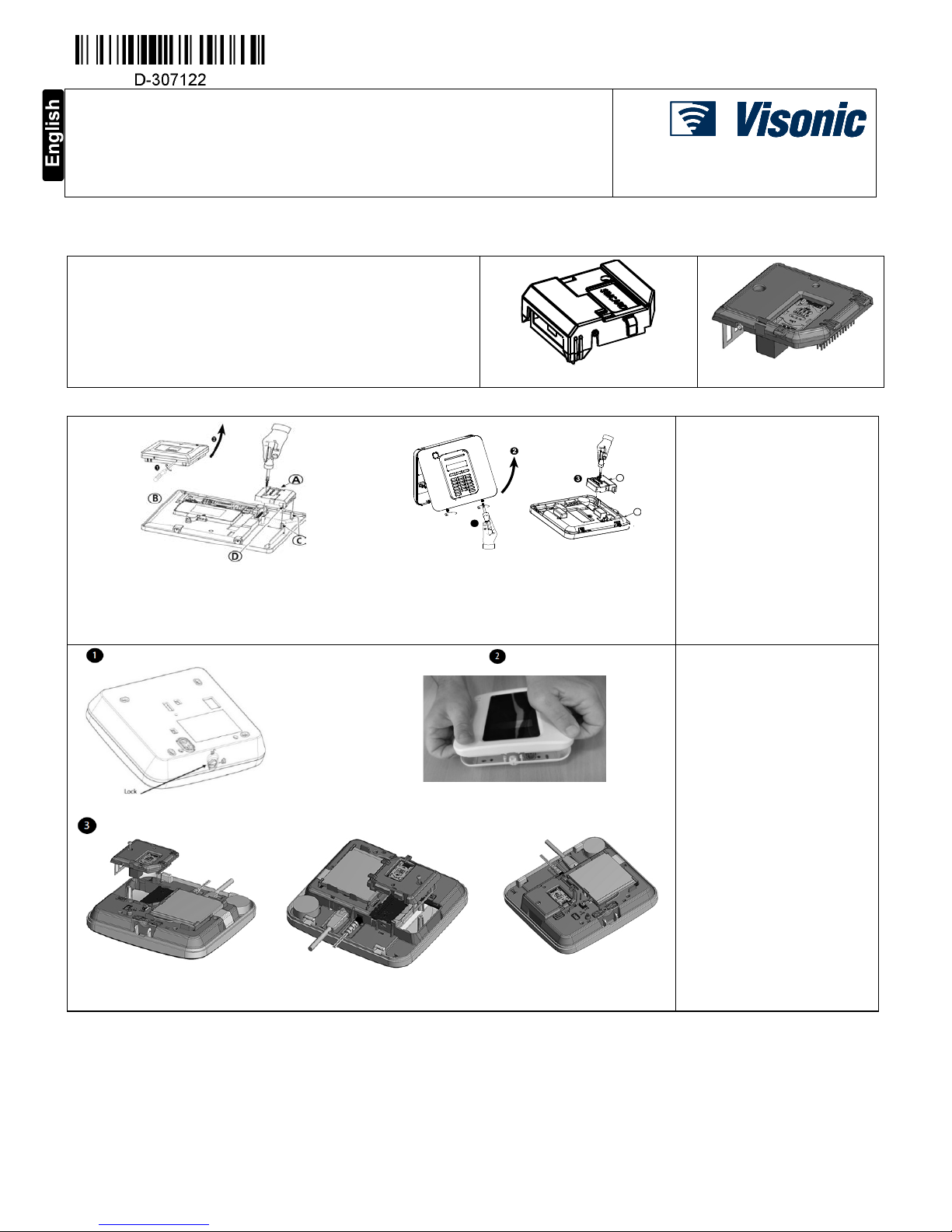
1. INTRODUCTION
The internal WCDMA-3G module enables the PowerMaster control panel to
operate over a GSM/GPRS/UMTS cellular network. The WCDMA-3G
model is optional and can be installed in any of the following control panels:
• PowerMaster-10 G2, see figure 1a for details.
• PowerMaster-30 G2, see figure 1a for details.
• PowerMaster-33 G2, see figure 1a for details.
• PowerMaster-360R, see figure 1b for details.
Fig. 1a WCDMA-3G PG2
Fig. 1b WCDMA-3G PG2
2. INSTALLATION
1. Release screws.
2. Remove front unit.
3. Plug in the WCDMA-3G
module and fasten it with the
screw.
4. For PowerMaster-33 G2,
ensure that the two leading
slots (D) on both sides of the
module slide along the two
leading ribs (C) on the front
unit.
Fig. 2.1 WCDMA-3G PG2 module mounting
PowerMaster-33 G2
Fig. 2.2 WCDMA-3G PG2 module mounting
PowerMaster-10 G2 and PowerMaster-30 G2
A. WCDMA-3G PG2 module B. Front unit C. *Leading ribs D. *Leading slot (1 of 2)
*PowerMaster-33 G2 only
1. Use a coin or 3 mm flathead
screwdriver to rotate the lock
by 90 degrees counter
clockwise to the unlocked
position.
2. Use minimal force to pull the
panel from the base.
3. Plug in the WCDMA-3G
module and fasten it with the
screw.
Fig. 2.3 WCDMA-3G PG2 module mounting PowerMaster-360R
A
B
1
Page 2
2 D-307122 WCDMA-3G PG2 Installation Instructions
Inserting the SIM card
Fig. 3 SIM card insertion
1. Slide top cover
2. Open cover
3. Align SIM card in cover (note cover orientation)
4. Slide SIM card into cover
5. Rotate cover to close
6. Lock cover to close
IMP ORTANT!
Do not insert or remove the SIM card when the
control panel is powered by AC power or battery.
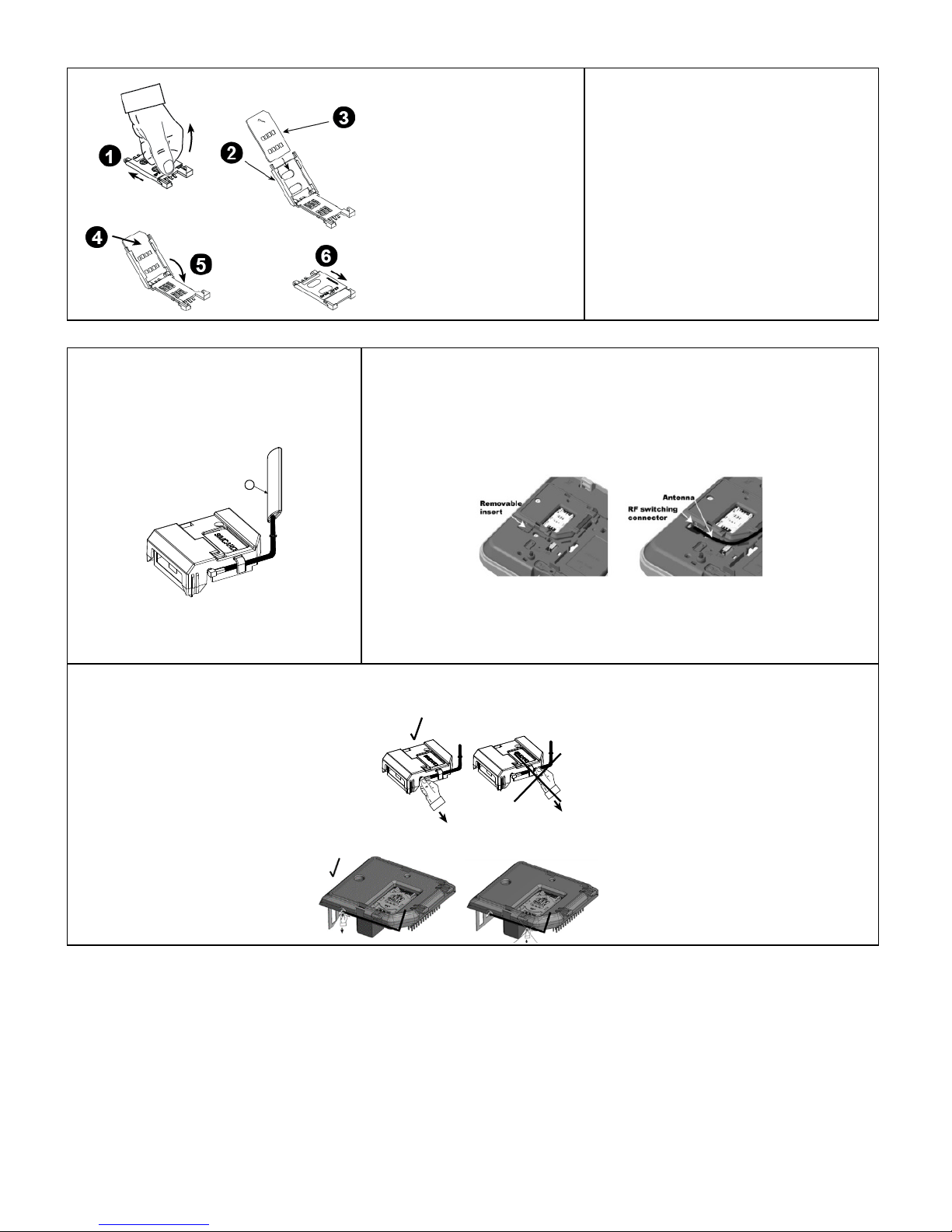
External cellular antenna installation - Optional
PowerMaster-10 G2, PowerMaster-30 G2 and
PowerMaster-33 G2
PowerMaster-360R
Mount the optional cellular external antenna on
the desired site surface, connect its connector to
the internal WCDMA-3G module and insert the
SIM card.
1. Push out the removable insert for the external antenna, see figure 4b for details.
2. Connect the external antenna to the RF switching connector, see figure 4b for details.
Fig. 4a Optional external cellular antenna
A. External cellular antenna
Fig. 4b Optional external cellular antenna
Warning!
If required to remove the external antenna, hold the connector but not the cable and pull it out. This prevents damage to the PCB.
PowerMaster-10 G2, PowerMaster-30 G2 and PowerMaster-33 G2:
PowerMaster-360R:
A
Page 3

D-307122 WCDMA-3G PG2 Installation Instructions
3
3. SPECIFICATIONS
Modem
UE910 EUR for WCDMA-3G 433 and WCDMA-3G 868,
UE910 NAR for WCDMA-3G 915 manufactured by TELIT
Ports
2 UART ports
Balanced analog audio port
Communication
Data, Voice, SMS
CODEC types
GSM: FR, HR, EFR, AMR
WCDMA: AMR
Supply voltage
3.4 – 4.2 VDC
(3.8 VDC recommended)
GPRS
Class 10
Bands
UE910 EUR:
GSM/GPRS: 900, 1800 MHz
WCDMA: 900, 2100 MHz
UE910 NAR:
GSM/GPRS: 850, 1900 MHz
WCDMA: 850, 1900 MHz
External SIM card
3V/1.8V
Transmission
power
GSM/GPRS:
Low bands – Class 4 (up to 2 W)
High bands – Class 1 (up to 1 W)
WCDMA: Class 3 (up to 0.25 W)
Minimum current
consumption
in idle mode
24 mA
Maximum current
consumption:
GPRS class 10 mode
GSM voice call
WCDM A voice call
WCDM A data
440 mA
220 mA
200 mA (Tx power = 10 dBm)
500 mA (Tx power = 22 dBm)
Sensitivity
GSM 850 – 109.5 dBm
GSM 900 – 109 dBm
DCS 1800 – 110 dBm
PCS 1900 – 109.5 dBm
WCDMA 2100 – 111 dBm
WCDMA 1900 – 110 dBm
WCDMA 850 – 111 dBm
WCDMA 900 – 110 dBm
Control
by AT commands (07.05, 07.07, and TELIT enhancement)
Dimensions
50x59x20.6 mm
4. COMPLIANCE WITH STANDARDS
Compliance with GSM Standards (USA): FCC 47 Part 22 (GSM850) and Part 24 (GSM 1900). EMC standard: FCC 47 Part 15.
Compliance with European CE Standards: EN301489-3,7, EN60950, EN50136-1 and -2
Compliance with GSM Standards (Europe): Complies with CE standards 3GPP TS 51.010-1, EN 301 511, EN301489-7, EN 301 908
W.E.E.E. Product Recycling Declaration
For information regarding the recycling of this product you must contact the company from which you originally purchased it. If you are discarding this product and not
returning it for repair then you must ensure that it is returned as identified by your supplier. This product is not to be thrown away with everyday waste.
Directive 2002/96/EC Waste Electrical and Electronic Equipment.
Page 4

4 D-307122 WCDMA-3G PG2 Installation Instructions
WAR RANT Y
Visonic Limited (the “Manufacturer" ) warrants this product only (the "Product") to the original purchaser
only (the “Purchaser”) agai nst defective workmanship and m aterials under normal use of the Product for a
period of twelve (12)
months from the date of shipment by the Manufacturer.
This Warranty is absolutely conditional upon the Product having been properly installed, maintained and
operated under conditions of normal use in accordance with t he Manufacturers recommended i nstallation
and operation instructions. P roducts which have become defective f or any other reason, according to the
Manufacturers discretion, such a s improper installation, f ailure to follow recommended i nstallation and
operational instructions, negl ect, willful damage, misuse or vandalism, ac cidental damage, alteration or
tampering, or repair by anyone other than the manuf acturer, are not covered by this Warranty.
There is absolutely no warranty on soft ware, and all software products are sold as a user l icense under the
terms of the software license agreement included wit h such Product."
The Manufacturer does not represent t hat this Product may not be com promised and/or circumvented or that
the Product will prev ent any death and/or personal inj ury and/or damage to propert y resulting from burgl ary,
robbery, fire or otherwise, or that the Product will in all cases provide adequate warning or protection. The
Product, properly install ed and maintained, only reduc es the risk of such ev ents without warning and it i s not
a guarantee or insurance that such events will not oc cur.
Conditions to Void Warranty
This warranty applies only to def ects in parts and workmanship r elating to normal use of the Pr oducts. It
does not cover:
• damage incurred in shipping or handling;
• damage caused by disaster such as fire, flood, wind, earthquak e or lightning;
• damage due to causes beyond t he control of the Sell er such as excessive volt age, mechanical shock or
water damage;
• damage caused by unauthorized att achment, alterations, modificati ons or foreign objects being used
with or in conjunction with the Products;
• damage caused by peripherals (unless such peripherals were supplied by the Seller;
• defects caused by failure to provide a suitable instal lation environment for the products;
• damage caused by use of the Products for purposes other than those f or which they were designed;
• damage from improper m aintenance;
• damage arising out of any other abuse, mishandling or im proper application of the Products.
Items Not Covered by Warranty:
In addition to the items which v oid the Warranty, the following items shall not be covered by Warranty: (i)
freight cost to the repair cent re; (ii) customs fees, taxes, or VAT that may be due; (iii) Products which are
not identified with the Sell er's product label and lot number or serial number; (iv) Products disassembled or
repaired in such a manner as to adversely affect perf ormance or prevent adequate inspection or testing to
verify any warranty claim. Access cards or tags returned for repl acement under warranty will be credit ed or
replaced at the Seller's option.
THIS WARRANTY IS EXCLUSIVE A
ND EXPRESSLY IN LIEU OF ALL OTHER WARRANTIES,
OBLIGATIONS OR LIABILITIES, WHETHER WRITTEN, ORAL, EXPRESS OR IMPLIED, INCLUDING
ANY WARRANTY OF MERCHANTABILITY OR FITNESS FOR A PARTICULAR PURPOSE, OR
OTHERWISE. IN NO CASE SHALL THE MANUFACTURER BE L IABLE TO ANYONE FOR ANY
CONSEQUENTIAL OR INCIDENTAL DAMAGES FOR BREACH O F THIS WARRANTY OR ANY OTHER
WARRANTIES WHATSOEVER, AS AFORESAID.
THE MANUFACTURER SHALL IN NO EVENT BE LI ABLE FOR ANY SPECIAL, INDIRECT,
INCIDENTAL, CONSEQUENTIAL OR PUNITIVE DAMAGES OR FOR LOSS, DAMAGE, OR EXPENSE,
INCLUDING LOSS OF USE, PROFITS, REVENUE, OR GOODWILL, DIRECTLY OR INDIRECTLY
ARISING FROM PURCHASER’S USE OR INABILITY TO USE T HE PRODUCT, OR FOR LOSS OR
DESTRUCTION OF OTHER PROPERTY OR FROM ANY OT HER CAUSE, EVEN IF MANUFACTURER
HAS BEEN ADVISED OF THE POSSIBILITY OF SUCH DAMAGE.
THE MANUFACTURER SHALL HAVE NO LIABILITY F OR ANY DEATH, PERSONAL AND/OR BODILY
INJURY AND/OR DAMAGE TO PROPERTY OR OTHER LOSS WHETHER DIRECT, INDIRE CT,
INCIDENTAL, CONSEQUENTIAL OR OTHERWISE, BASED ON A CLAIM THAT T HE PRODUCT
FAILED TO FUNCTION. HOWEVER, IF THE MANUFACTURER IS HELD LIABLE , WHETHER DIRECTLY
OR INDIRECTLY, FOR ANY LOSS O R DAMAGE ARISING UNDER THIS LIMITED WARRA NTY, THE
MANUFACTURER'S MAXIMUM LIABILITY (IF ANY) SHALL NOT IN ANY CASE EXCEED THE
PURCHASE PRICE OF THE PRODUCT INVOLVED,
WHICH SHALL BE FIXED AS LIQUIDATED
DAMAGES AND NOT AS A PENALTY, AND SHALL BE THE COMPLETE AND EXCLUSIVE REMEDY
AGAINST THE MANUFACTURER.
When accepting the delivery of the Product, the Purchaser agree s to the said conditions of sale and
warranty and he recognizes having been inform ed of.
Some jurisdictions do not al low the exclusion or l imitation of incidental or c onsequential damages, so these
limitations may not apply under certain ci rcumstances.
The Manufacturer shall be under no liabilit y whatsoever arising out of the corruption and/or malf unctioning of
any telecommunication or electroni c equipment or any programs.
The Manufacturers obli gations under this Warranty are lim ited solely to repair and/ or replace at the
Manufacturer’s discretion any Pr oduct or part thereof that may prove def ective. Any repair and/or
replacement shall not ext end the original Warranty period. The M anufacturer shall not be responsible f or
dismantling and/or reinstall ation costs. To exercise this Warranty the Product must be returned t o the
Manufacturer freight pre-paid and insured. All frei ght and insurance costs are the responsibi lity of the
Purchaser and are not included in this Warranty.
For sales in Israel only:
The Purchaser shall comply with the provisions of the Israeli Consumer Protection Law – 1981(" Consumer
Protection Law") related regulat ions, including the Israeli Consumer Protection Regulati ons (Warranty
Sticker), 5772-2012) ("Regul ations"), including, wit hout limitation (i) provi ding its customers with at l east
the minimum warranty required by t he Consumer Protection Law, and (ii) ensuri ng that a warranty certificate
and a warranty sticker (as defined in the Regulati ons) ("Warranty Sticker") shall be attached to any sold
Products and the date of the sale of t he Product to the consumer or the end-user shall be added i n a
readable manner on t he Warranty Stick er.
In no event shall the Purchaser’s compliance with the Consumer Protection Law and Regulat ions expand
any of the Manufacturer's warranty obl igations under this warranty, and the P urchaser shall be responsible
for any warranty that it prov ides with respect to the Products whic h exceeds or is different from this
warranty.
This warranty shall not be m odified, varied or extended, and the Manufact urer does not authorize any
person to act on its behalf in the modificati on, variation or extension of this warranty. Thi s warranty shall
apply to the Product only. All product s, accessories or attachments of other s used in conjunction with the
Product, including batteri es, shall be covered solely by thei r own warranty, if any. The Manuf acturer shall
not be liable for any damage or l oss whatsoever, whether directly, indirectl y, incidentally, consequentiall y or
otherwise, caused by the m alfunction of the Product due t o products, accessories, or att achments of others,
including batteries, used in c onjunction with the Produc ts. This Warranty is excl usive to the original
Purchaser and is not assignable.
This Warranty is in addition to and does not af fect your legal rights. Any provision in this warranty which i s
contrary to the Law in the state or country were the Product is suppli ed shall not apply.
Governing Law
:
This disclaimer of warranties and limit ed warranty are governed by the domestic laws of I srael.
Warning
The user must follow the Manufacturer’s instal lation and operational instructi ons including testing the
Product and its whole system at least once a week and to take all nec essary precautions for his/her
safety and the protec tion of his/her property.
* In case of a confli ct, contradiction or interpret ation between the English v ersion of the warranty and
other versions, the E nglish version shall prevail.
EMAIL: info@visonic.com
INTERNET: www.visonic.com
VISONIC LTD. 2017 WCDMA-3G PG2 Installation Instructions D-307122 (REV 0, 09/17)
 Loading...