

Page 1
TOWER-32AM PG2 /
TOWER-32AM K9 PG2
Wireless PowerG, Dual Technology, Mirror,
PIR Motion Detector with Anti-mask
1. INTRODUCTION
The TOWER-32AM PG2 and TOWER-32AM K9 PG2 (pet-immune) Dual Technology are 2-way,
microprocessor-controlled, wireless digital mirror PIR detectors which include the following features:
Adaptive Active Infra-Red Anti-Masking technology providing the most advanced reliable protection
against intentional masking attempts (patent pending)
Includes a fully supervised PowerG transceiver.
24 GHz K-band microwave module.
Incorporates patent pending black mirrors for extremely high white light immunity.
Advanced elliptical / parabolic mirror technology (patent pending)
Provides multiple curtain coverage (patent pending)
V-slot® optic technology (patent pending) for improved robustness, anti-vandalism and for very high
reliability.
Creep zone protection
TOWER-32AM K9 PG2 can distinguish between human beings and pets weighing up to 18 kg (40 lb)
The advanced True Motion Recognition™ algorithm (patented) allows distinguishing between the true
motion of an intruder and any other disturbances which may cause false alarms.
Built-in auto diagnostic for both PIR and microwave detectors.
Built-in link quality indicators; no need for the installer to physically approach the control panel thus
making installation faster and easier.
No vertical adjustment is needed.
Motion event counter determines whether 1 or 2 consecutive motion events will trigger an alarm.
Automatic termination of walk-test after 15 minutes.
Microprocessor controlled, digital TMR signal processing with dual-slope digital temperature compensation.
Sealed chamber protects the optical system.
Front and back tamper protection.
Microwave anti-masking
Disguise mode that detects an intruder who cloaks his IR radiation
Installation Instructions
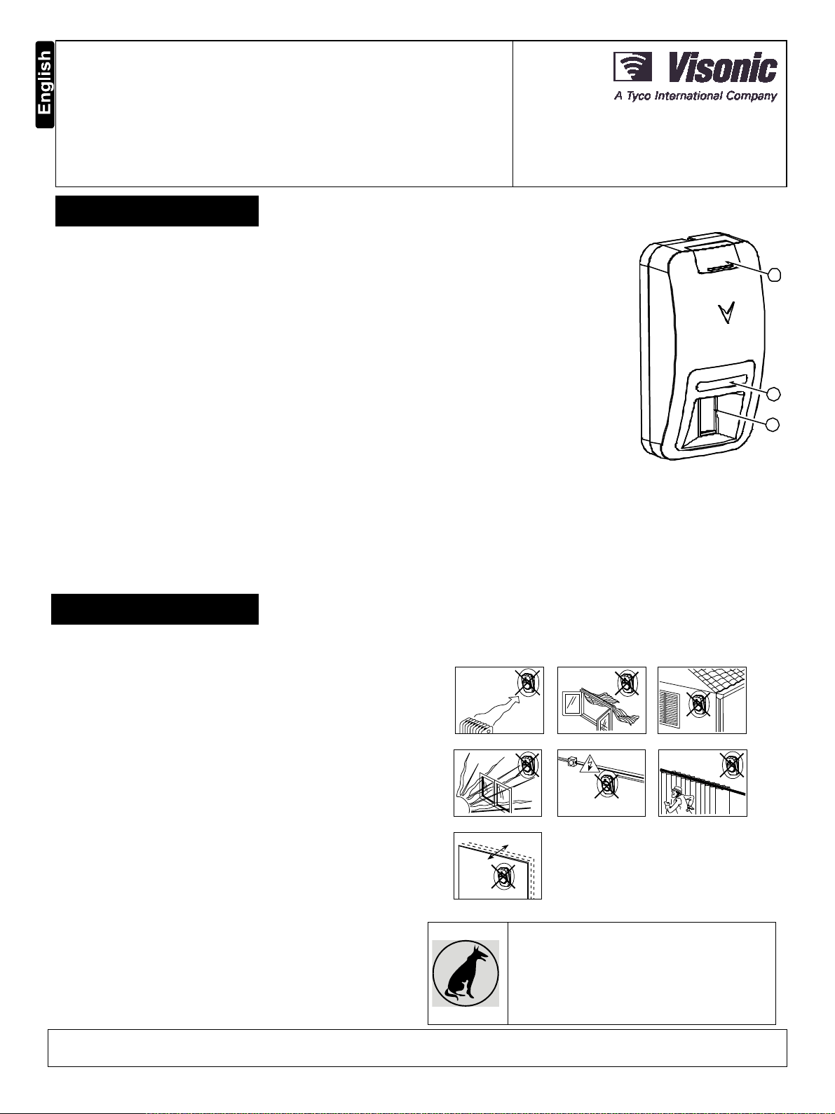
A
B
C
A. Screw cover
B. LED
C. PIR optical window
Figure 1. General View
2. INSTALLATION
2.1 General Guidance (see Fig. 2)
1. Keep away from heat sources.
2. Do not expose to air drafts.
3. Do not install outdoors.
4. Avoid direct sunshine.
5. Keep wiring away from power cables.
6. Do not install behind partitions.
7. Mount on solid stable surface.
WARNING! To comply with FCC and IC RF exposure compliance requirements, the PIR detector should be located at a distance of at
least 20 cm from all persons during normal operation. The antennas used for this product must not be co-located or operated in
conjunction with any other antenna or transmitter.
1 2 3
4 5 6
7
Figure 2. General Guidelines
Important! The detector is immune to 18 kg (40
lb) animals moving on the floor or climbing on
furniture as long as the activity takes place below
1 m (3 ft). Above the 1 m (3 ft) height limit, the pet
immunity will decrease as the pet gets closer to
the detector. It is therefore recommended to select
a mounting location that minimizes potential close
proximity of animals.
D-303780 TOWER-32AM PG2, TOWER-32AM K9 PG2 Installation Instructions 1
Page 2
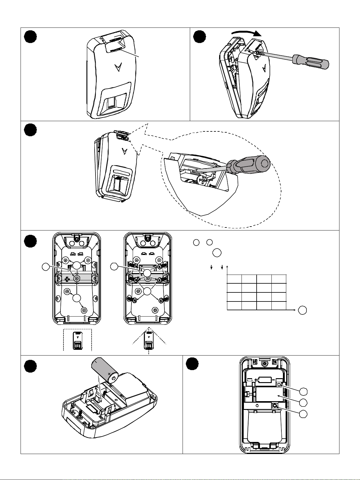
2.2 Mounting
1
3
2
4
5
Note: For the desired detector's range and height, use mounting
a
holes
or b, as specified in the table.
A
C
a
C
a
b
b
a – upper surface (without downward tilt)
b – lower surface (with downward tilt)
ft m
10 3.0
9 2.7
8 2.4
7 2.1
6 1.8
b
b
b
b
b
b
b
a
b
a
b
a
b
15
309451260 ft
6
a
a
a
B
15 m
6
D
E
F
2 D-303780 TOWER-32AM PG2, TOWER-32AM K9 PG2 Installation Instructions
Page 3

1. On the indicated location, lift the screw cover upward using your thumb.
2. Release the screw and open the cover in the direction shown by the arrow.
3. Insert a screwdriver into the slot and then push inward to separate the base from the cover.
4. Set the desired detector range.
5. Insert battery while observing polarity.
A. Mounting height
B. Coverage range
C. Break-away base segment (shaded)
D. Enroll button (use a screwdriver to press the recessed button)
E. Battery
F. Tamper switch
CAUTION! THE BACK TAMPER SWITCH WILL NOT PROTECT THE UNIT UNLESS THE BREAK-AWAY BASE SEGMENT IS
SECURED TO THE WALL WITH AT LEAST ONE SCREW.
CAUTION! RISK OF EXPLOSION IF BATTERY IS REPLACED BY AN INCORRECT TYPE. DISPOSE OF USED BATTERY
ACCORDING TO MANUFACTURER'S INSTRUCTIONS.
Figure 3. Mounting
2.3. Enrollment
Refer to the PowerMaster control panel's Installer Guide and follow the procedure under the "02:ZONES/DEVICES" option of the
Installer Menu. A general description of the procedure is provided in the following flow chart.
Step 1 Step 2 Step 3 Step 4 Step 5
Enter the Installer menu
and select
“02:ZONES/DEVICES”
02:ZONES/DEVICES
Select "ADD NEW
DEVICE"
See Note 1
MODIFY DEVICES
Step 6 Step 7 Step 8
Enter PARTITIONS.
See Note 2
Z14:PARTITIONS
Assign partitions to the
detector by pressing the
, and
buttons on the panel
F02:P1 P2 P3
means scroll and select
Enroll the device or enter the
device ID
ENROLL NOW or ADD NEW DEVICES
ENTR ID:XXX-XXXX
Select the "DEV SETTINGS"
option and refer to the
section below to configure
the detector parameters.
F02: DEV SETTINGS
Select the desired detector
number for the new
detector
Z14:Motion Sens
ID No. 123-XXXX
Configure Location,
Zone Type & Chime
Parameters
Z14.LOCATION
Z14.ZONE TYPE
Z14.SET CHIME
Notes:
1. If the detector is already enrolled, you can configure the detector parameters and assign partitions via the “Modify Devices” option –
see Step 2.
2. PARTITIONS will appear only if PARTITIONING was previously enabled in a panel that supports the Partitioning feature (for further
details, see "Partitioning" in the PowerMaster Installer Guide).
2.4. Configuring the Detector Parameters
Enter the menu and follow the configuration instructions for the TOWER-32AM PG2 PIR detector as described in
the following table.
Alarm LED
MW RANGE
Event Counter
DISARM Activity
DEVICE SETTINGS
Option Configuration Instructions
Define whether or not the alarm LED indication will be activated.
Optional settings: ON (default) and OFF.
Define the detection range of the microwave channel.
Optional settings: Maximum (default); Medium and Minimum.
Define whether an alarm will be activated upon continued motion (low sensitivity) or upon a single alarm event
(high sensitivity).
Optional settings: LOW sensitive (default) and HIGH sensitive.
Define whether or not to set the activity time during disarm.
Optional settings: NOT Active (default), YES – no delay, YES + 5s delay, YES + 15s delay, YES + 30s
delay, YES + 1m delay, YES + 2m delay, YES + 5m delay, YES + 10m delay, YES + 20m delay and YES +
60m delay.
D-303780 TOWER-32AM PG2, TOWER-32AM K9 PG2 Installation Instructions 3
Page 4

ANTI MASKING
MW ANTI
DISGUISE MODE
Define the activity and the sensitivity level of the PIR anti-masking.
Optional settings: LOW sensitive (default), HIGH sensitive and disabled.
Define whether to enable or disable the anti-masking of the microwave sensor.
Optional settings: disabled (default), and enabled.
Disguise mode is used to detect movement of an intruder who cloaks his IR radiation to avoid detection. Define
whether to enable or disable this mode.
Optional settings: disabled (default), and enabled.
3. LOCAL DIAGNOSTICS TEST
A. Separate the base from the cover (see Fig. 3).
B. Put back the cover to return the tamper switch to its normal (undisturbed) position, and then secure the front cover to the base with the
case closure screw.
C. The TOWER-32AM PG2 will enter a 2 min. stability period. During this time the red LED blinks.
D. Walk-test the coverage area - see Figure 4. Walk across the far end of coverage pattern in both directions; the red LED lights each
time your motion is detected followed by 3 LED blinks.
The following table indicates the received signal strength indication.
LED response Reception
Green LED blinks Strong
Orange LED blinks Good
Red LED blinks Poor
No blinks No communication
IMPORTANT! Reliable reception must be assured. Therefore, "poor" signal strength is not acceptable. If you receive a "poor" signal
from the detector, re-locate it and re-test until a "good" or "strong" signal strength is received.
Note: For detailed Diagnostics Test instructions refer to the control panel Installer Guide.
4. EVENT INDICATIONS
LED Indications
Red LED blinks Stabilization (warm-up 120 sec)
Red LED ON 0.2 sec. Tamper open / close
Red on 2 sec. Intruder alarm
Yellow LED on AM detection – diagnostic mode
Yellow LED blinks slowly (0.2 sec. ON, 30 sec. OFF) AM detection – Normal mode
Yellow and red LED blink simultaneously (0.2 sec. ON [both], 0.2 sec. OFF) Self-test failure – Diagnostic mode
Yellow and red LED blink simultaneously slowly (0.2 sec. ON [both], 30 sec. OFF) Self-test failure – Normal mode
Green LED blinks PIR detection – Diagnostic mode
Green LED on Microwave detection – diagnostic mode
Event
5. SPECIAL COMMENTS
Even the most sophisticated detectors can sometimes be defeated or may fail to warn due to: DC power failure / improper connection,
malicious masking of the lens, tampering with the optical system, decreased sensitivity in ambient temperatures close to that of the
human body and unexpected failure of a component part.
The above list includes the most common reasons for failure to detect intrusion, but is by no means comprehensive. It is therefore
recommended that the detector and the entire alarm system be checked weekly, to ensure proper performance.
An alarm system should not be regarded as a substitute for insurance. Home and property owners or renters should be prudent enough
to continue insuring their lives and property, even though they are protected by an alarm system.
This device has been tested and found to comply with the limits for a Class B digital device, pursuant to Part 15 of the FCC Rules. These
limits are designed to provide reasonable protection against harmful interference in residential installations. This equipment generates
uses and can radiate radio frequency energy and, if not installed and used in accordance with the instructions, may cause harmful
interference to radio and television reception.
However, there is no guarantee that interference will not occur in a particular installation. If this device does cause such interference,
which can be verified by turning the device off and on, the user is encouraged to eliminate the interference by one or more of the
following measures:
– Re-orient or re-locate the receiving antenna.
– Increase the distance between the device and the receiver.
– Connect the device to an outlet on a circuit different from the one that supplies power to the receiver.
– Consult the dealer or an experienced radio/TV technician.
4 D-303780 TOWER-32AM PG2, TOWER-32AM K9 PG2 Installation Instructions
Page 5

WARNING! Changes or modifications to this unit not expressly approved by the party responsible for compliance could void the user’s
y
r
/
(
y (
y
y
y
y
y
A
(
authority to operate the equipment.
This device complies with FCC Rules Part 15 and with Industry Canada licence-exempt RSS standard(s). Operation is subject to two
conditions: (1) This device may not cause harmful interference, and (2) this device must accept any interference that may be received
or that may cause undesired operation.
6. COMPLIANCE WITH STANDARDS
Compliance with Standards
Europe (CE): EN 50131-1, EN 300220, EN 301489, EN 60950, EN 50130-4, EN 50130-5,
EN 50131-2-2 Grade 3 Class II, EN 50131-6
USA: CFR 47 Part 15 (FCC)
Canada: RSS 210
UK: This product is suitable for use in systems installed to conform to PD6662:2010 at Grade 2 and
environmental class 2. DD243 and BS8243
The PowerG peripheral devices have two-way communication functionality, providing additional benefits as described in the technical
brochure. This functionality has not been tested to comply with the respective technical requirements and should therefore be considered
outside the scope of the product’s certification.
The technical documentation as required by the European Conformity Assessment procedure is kept at:
UNIT 6 MADINGLEY COURT CHIPPENHAM DRIVE KINGSTON MILTON KEYNES MK10 0BZ. TEL: (0845) 0755800 FAX: (0845) 0755801
W.E.E.E. Product Recycling Declaration
For information regarding the recycling of this product you must contact the company from which you orignially purchased it. If you are discarding this product and not
returning it for repair then you must ensure that it is returned as identified by your supplier. This product is not to be thrown away with everyday waste.
Directive 2002/96/EC Waste Electrical and Electronic Equipment.
APPENDIX: SPECIFICATIONS
GENERAL
Detector T
Lens Data No. of Beam Elements:
MW Coverage Maximum: 15 m (49 ft)
pe Dual element low-noise pyroelectric senso
18x3=54 far parabolic mirror segments
No. of Curtain Elements:
18
90°
Medium: 10 m (33 ft) / 90°
Minimum: 5 m
16 ft) / 90°
A. Horizontal view
B. Vertical view
C. 18 near curtains
D. 18 far curtains
E. Microwave coverage
Figure 4. Coverage Pattern & Walk-test
Pet Immunit
ELECTRICAL
Sensor T
Power Suppl
only) Up to 18 kg (40 lb)
pe K-Band Doppler module: 24 GHz
Type C
Internal Battery 3V Lithium battery, type CR-123A or equivalent
Nominal Batter
Batter
Life (for typical use) 5 years
FUNCTION
Capacity 1450 mA/h
L
True Motion Event 2 remote selections - 1
Note: For UL installations use Panasonic, San
OFF) or 2 (ON) motion events
o, GP or Varta only. Use only the above battery.
D-303780 TOWER-32AM PG2, TOWER-32AM K9 PG2 Installation Instructions 5
Page 6

V
erification
y
g
g
g
r
)
y
(
)
r
(
Alarm Period 2 seconds
WIRELESS
Frequenc
Band (MHz) Europe and rest of world: 433-434, 868-869 USA: 912-919
Communication Protocol PowerG
Supervision Si
naling at 4-min. intervals
Tamper Alert Reported when a tamper event occurs and in any subsequent message, until the tamper switch is
restored
MOUNTING
Height
Installation Options
ACCESSORIES
1.8 – 3.0 m (6 - 10 ft).
Surface or corner
BR-1: Surface mounted swivel bracket, adjustable 30° down and 45° left/45° right.
BR-2: BR-1 with a corner adapter
BR-3: BR-1 with a ceiling adapter
ENVIRONMENTAL
RFI Protection >20 V/m up to 2000 MHz, excludin
Operatin
Temperatures -10°C to 50°C (14°F to 122°F) indoo
inband frequencies
Storage Temperatures -20°C to 60°C (-4°F to 140°F
Humidity Average relative humidity of up to approximately 75% non-condensing. For 30 days per year the
relative humidit
may vary between 85 % and 95 % non-condensing
PHYSICAL
Size
H x W x D) 115 x 60 x 48 mm (4-1/2 x 2-5/16 x 1-15/16”
Weight (with battery) 90 g (3 oz).
Colo
White
PATENTS U.S. Patents 5,693,943 6,211,522 D445,709
another patent pending)
WARRANTY
Visonic Limited (the “Manufacturer") warrants this product only (the "Product") to the original purchaser only (the
“Purchaser”) against defective workmanship and materials under normal use of the Product for a period of twelve
(12) months from the date of shipment by the Manufacturer.
This Warranty is absolutely conditional upon the Product having been properly installed, maintained and operated
under conditions of normal use in accordance with the Manufacturers recommended installation and operation
instructions. Products which have become defective for any other reason, according to the Manufacturers
discretion, such as improper installation, failure to follow recom mended installation and operational instructions,
neglect, willful damage, misuse or vandalism, acc idental damage, alteration or tampering, or repair by anyone
other than the manufacturer, are not covered by this Warranty.
The Manufacturer does not represent that this Product may not be compromised and/or circumvented or that the
Product will prevent any death and/or personal injury and/or damage to property resulting from burglary, robbery,
fire or otherwise, or that the Product will in all cases provide adequate warning or protection. The Product,
properly installed and maintained, only reduces the risk of such events without warning and it is not a guarantee
or insurance that such events will not occur.
THIS WARRANTY IS EXCLUSIVE AND EXPRESSLY IN LIEU OF ALL OTHER WARRANTIES, OBLIGATIONS
OR LIABILITIES, WHETHER WRITTEN, ORAL, EXPRESS OR IMPLIED, INCLUDING ANY WARRANTY OF
MERCHANTABILITY OR FITNESS FOR A PARTICULAR PURPOSE, OR OTHERWISE. IN NO CASE SHALL
THE MANUFACTURER BE LIABLE TO ANYONE FOR ANY CONSEQUENTIAL OR INCIDENTAL DAMAGES
FOR BREACH OF THIS WARRANTY OR ANY OTHER WARRANTIES WHATSOEVER, AS AFORESAID.
THE MANUFACTURER SHALL IN NO EVENT BE LIABLE FOR ANY SPECIAL, INDIRECT, INCIDENTAL,
CONSEQUENTIAL OR PUNITIVE DAMAGES OR FOR LOSS, DAMAGE, OR EXPENSE, INCLUDING LOSS
OF USE, PROFITS, REVENUE, OR GOODWILL, DIRECTLY OR INDIRECTLY ARISING FROM
PURCHASER’S USE OR INABILITY TO USE THE PRODUCT, OR FOR LOSS OR DESTRUCTION OF
OTHER PROPERTY OR FROM ANY OTHER CAUSE, EVEN IF MANUFACTURER HAS BEEN ADVISED OF
THE POSSIBILITY OF SUCH DAMAGE.
THE MANUFACTURER SHALL HAVE NO LIABILITY FOR ANY DEATH, PERSONAL AND/OR BODILY
INJURY AND/OR DAMAGE TO PROPERTY OR OTHER LOSS WHETHER DIRECT, INDIRECT, INCIDENTAL,
CONSEQUENTIAL OR OTHERWISE, BASED ON A CLAIM THAT THE PRODUCT FAILED TO FUNCTION.
However, if the Manufacturer is held liable, whether directly or indirectly, for any loss or damage arising under this
limited warranty, THE MANUFACTURER'S MAXIMUM LIABILITY (IF ANY) SHALL NOT IN ANY CASE
EXCEED THE PURCHASE PRICE OF THE PRODUCT, which shall be fixed as liquidated damages and not as a
penalty, and shall be the complete and exclusive remedy against the Manufacturer.
When accepting the delivery of the Product, the Purchaser agrees to the said c onditions of sale and warranty and
he recognizes having been informed of.
Some jurisdictions do not allow the exclusion or limitation of incidental or c onsequential damages, so these
limitations may not apply under certain circumstances.
The Manufacturer shall be under no liability whatsoever arising out of the corruption and/or m alfunctioning of any
telecommunication or electronic equipment or any programs.
The Manufacturers obligations under this W arranty are limited solely to repair and/or replace at the
Manufacturer’s discretion any Product or part ther eof that may prove defective. Any repair and/or replacement
shall not extend the original Warranty period. The Manufacturer shall not be responsible for dismantling and/or
reinstallation costs. To exercise this Warranty the Product must be returned to the Manufacturer freight pre-paid
and insured. All freight and insurance costs are the responsibility of the Purchaser and are not included in this
Warranty.
This warranty shall not be modified, varied or extended, and the Manufacturer does not authorize any person to
act on its behalf in the modification, variation or extension of this warranty. This warranty shall apply to the
Product only. All products, accessories or attachments of others used in conjunction with the Product, including
batteries, shall be covered solely by their own warranty, if any. The Manufacturer shall not be liable for any
damage or loss whatsoever, whether directly, indirectly, incidentally, consequentially or otherwise, caused by the
malfunction of the Product due to products, ac cessories, or attachments of others, including batteries, used in
conjunction with the Products. This Warranty is exclusive to the original Purchaser and is not assignable.
This Warranty is in addition to and does not af fect your legal rights. Any provision in this warranty which is
contrary to the Law in the state or country were the Product is supplied shall not apply.
Warning: The user must follow the Manufacturer’s installation and operational instructions including testing the
Product and its whole system at least once a week and to take all necessary precautions for his/her s afety and
the protection of his/her property.
1/08
VISONIC LTD. (ISRAEL): P.O.B 22020 TEL-AVIV 61220 ISRAEL. PHONE: (972-3) 645-6789, FAX: (972-3) 645-6788
VISONIC INC. (U.S.A.): 65 WEST DUDLEY TOWN ROAD, BLOOMFIELD CT. 06002-1376. PHONE: (860) 243-0833, (800) 223-0020. FAX: (860) 242-8094
VISONIC LTD. (UK): UNIT 6 MADINGLEY COURT CHIPPENHAM DRIVE KINGSTON MILTON KEYNES MK10 0BZ. TEL: (0845) 0755800 FAX: (0845) 0755801.
PRODUCT SUPPORT: (0845) 0755802
VISONIC GmbH (D-A-CH): KIRCHFELDSTR. 118, D-40215 DÜSSELDORF, TEL.: +49 (0)211 600696-0, FAX: +49 (0)211 600696-19
VISONIC IBERICA: ISLA DE PALMA, 32 NAVE 7, POLÍGONO INDUSTRIAL NORTE, 28700 SAN SEBASTIÁN DE LOS REYES, (MADRID), ESPAÑA.TEL (34) 91659-3120,
FAX (34) 91663-8468. www.visonic-iberica.es
INTERNET: www.visonic.com
VISONIC LTD. 2012 TOWER-32AM PG2, TOWER-32AM K9 PG2 D-303780 (Rev. 1, 9/12)
6 D-303780 TOWER-32AM PG2, TOWER-32AM K9 PG2 Installation Instructions
 Loading...