

Page 1

TMD-560 PG2
Wireless PowerG Temperature Detector
1. INTRODUCTION
The TMD-560 PG2 is a wireless PowerG detector used with the PowerMaster alarm
system. The detector is designed to update the alarm system control panel upon any
change of temperature. The control panel then generates an alarm message when the
temperature has reached a certain temperature point. A restore message is generated
when it crosses back the threshold temperature point. There are a number of selectable
fixed temperature points at the control panel and the user can enable one or more
temperature point. The TMD-560 PG2 can be used in instances where temperature
detection is critical.
Other examples of detector usage are as follows:
Activating and deactivating pipe heaters at locations where low temperatures may
cause the water in pipes to freeze.
Warn of possible electrical device malfunction due to high or low temperature levels.
Alerting elderly people of a significant rise or drop in room temperature.
The TMD-560 PG2 detects both indoor and outdoor temperatures. The detector monitors room temperature using an internal sensor. For outdoor
or refrigerator installations, a waterproof temperature probe (optional) is used.
When the probe is connected, the temperature measurement is performed only by the probe sensor. When the probe is not connected and its
terminals are shorted, the temperature measurement is performed only by the detector's internal sensor.
Once the predefined temperature is reached, the alarm system control panel sends a notification to the central station or uses the PGM/X-10
controls to switch on a connected appliance, for example, a heater or air conditioner.
Note: When using the temperature probe to monitor refrigerator temperature, the temperature probe is installed inside the refrigerator, while the
detector is installed on the wall or ceiling. For outdoor installations, the temperature probe is installed outdoors, while the detector is installed
indoors.
Based on the unique PowerG technology, the TMD-560 PG2 includes a "smart" anti- collision transmission sequence mechanism that prevents
collisions with transmitted messages from other PowerG devices.
For further reliability, the TMD-560 PG2 tamper switch is activated when the detector cover (see Figure 2) is removed.
Operating power is obtained from an on-board 3 V Lithium battery. A weak battery will result in a “low battery” message.
Features
The TMD-560 PG2 is compatible with PowerMaster control panels.
Internal temperature sensor
An external temperature optional probe (cat. no. 99-300890) enables outdoor and refrigerator temperature sensing
Fully supervised PowerG detector
Long battery life
Low battery supervision
Probe disconnected supervision
Link quality indication
Installation Instructions
Figure 1. TMD-560 PG2 with Temperature Probe
2. INSTALLATION, ENROLLING AND CONFIGURING
2.1. Mounting and Battery Insertion
1. Installation:
The TMD-560 PG2 can be installed indoors on walls or on ceilings and in any direction. For installing outdoors or on refrigerators use the
temperature probe (see Figures. 1 and 3).
Mount the bracket in the monitored area as close as possible to the control panel to ensure optimum reception of the RF signal.
If there is a short circuit between the two probe terminals (factory default) the detector measures the temperature using its internal sensor. If
the probe terminals are not shorted, the internal sensor is disabled and the temperature is measured by the probe.
Note: Open probe terminals generate a "Probe Disconnected Trouble" transmission.
2. Insert the battery between the battery clips (see Figure 2), at the correct polarity. For proper operation, only a Lithium battery (type CR123
or equivalent) should be used.
Note: When replacing a battery, it is necessary to wait 30 seconds between removing the used battery and inserting the new one.
Caution! Risk of explosion if battery is replaced by an incorrect type. Dispose of used batteries according to the manufacturer's instructions.
D-303471 TMD-560 PG2 Installation Instructions 1
Page 2
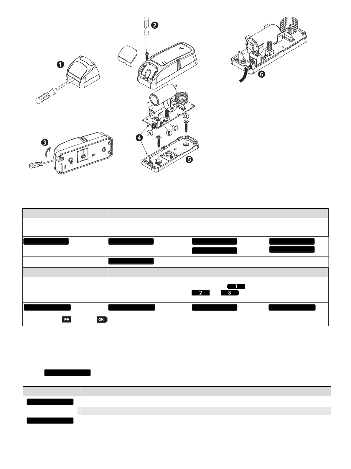
Figure 2. Mounting
Figure 3. Temperature Probe Mounting
1. Insert a flat-edged screwdriver into the slot and push
upward to remove cover.
2. Remove screw.
3. Separate base from cover.
4. Flex catch and remove P.C. board.
5. Mark and drill 2 holes in the mounting surface. Fasten
base with 2 countersunk screws.
6. Reinsert P.C. board into base and connect the two
wires of the probe to the terminal block.
A. Terminal Jumper
B. Enroll button
C. LED
D. Internal Temperature Sensor
2.2. Enrollment
Refer to the PowerMaster panel's Installer Guide and follow the procedure under the "02:ZONES/DEVICES" option of the Installer Menu.
A general description of the procedure is provided in the following flow chart.
Step 1 Step 2 Step 3 Step 4
Enter the Installer menu and select
“02:ZONES/DEVICES”
02:ZONES/DEVICES
Select "ADD NEW DEVICE"
See Note 1
Step 5 Step 6 Step 7 Step 8
Configure Location parameter
MODIFY DEVICES
Enter PARTITIONS.
See Note
2
means scroll and select
Notes:
[1] If the temperature detector device is already enrolled you can configure the temperature detector device parameters via the “Modify Devices”
option – see Step 2.
PARTITIONS will appear only if PARTITIONING was previously enabled in a panel that supports the Partitioning feature (for further
[2]
details, see "Partitioning" in the PowerMaster Installer Guide).
Enroll the device or enter the
device ID
ENROLL NOW or ADD NEW DEVICES
ENTR ID:XXX-XXXX
Assign partitions to the detector
by pressing the
the panel
Z06:P1 P2 P3
,
and buttons on
Select the desired detector
number for the new flood
detector
Z06:Temp. Sensor
ID No. 250-XXXX
Continue to section 2.3
Z06.DEV SETTINGS Z06.LOCATION Z06.PARTITIONS
2.3. Configuring the Temperature Device Parameters
Enter the menu and follow the configuration instructions for the TMD-560 PG2 temperature detector device as described in
the following table.
This option is available only through the DEFINE DEFAULTS settings, (for further details, see the PowerMaster Installer Guide).
2 D-303471 TMD-560 PG2 Installation Instructions
Z06:DEV SETTINGS
Option Configuration Instructions
TEMPERATURE C/F
VERY HOT > 35C
Set the detector to detect temperatures in either Celsius or Fahrenheit.
Options: Celsius C (default) or Fahrenheit F.
Define whether or not the control panel will report a "very hot" alert when the temperature rises above 35C (95F)
for at least 10 minutes. Alert restore will occur when the temperature drops below 34C (93F) for the duration of
10 minutes.
Page 3

y
y
/
Options: Disabled (default) or Enabled.
COLD < 19C
FREEZING <7ºC
FREEZER >–10ºC
Define whether or not the control panel will report a "cold" alert when the temperature drops below 19C (66F) for
at least 10 minutes. Alert restore will occur when the temperature rises above 20C (68F) for the duration of 10
minutes.
Options: Disabled (default) or Enabled.
Define whether or not the control panel will report a "freezing" alert when the temperature drops below 7C (45F)
for at least 10 minutes. Alert restore will occur when the temperature rises above 8C (48F) for the duration of 10
minutes.
Options: Disabled (default) or Enabled.
Define whether or not the control panel will report a "freezer" alert when the temperature rises above -10C (14F)
for at least 30 minutes. Alert restore will occur when the temperature drops below -11C (12F) for the duration of
10 minutes.
Options: Disabled (default) or Enabled.
Note: The temperature must pass beyond the threshold for the required duration in order to generate an alarm or restore transmission.
2.4. Temperature Display
For instructions on displaying the temperature of zones on the control panel as measured by TMD-560 detectors, refer to the PowerMaster
Installer Guide, section 4.2 "Conducting a Periodic Test".
3. LOCAL DIAGNOSTICS TEST
Before testing, separate the base from the cover (see Figure 2).
A. Press the tamper switch once and release it.
B. After 2 seconds the LED blinks 3 times.
The following table indicates received signal strength indication.
LED response Reception
Green LED blinks Strong
Orange LED blinks Good
Red LED blinks Poor
No blinks No communication
C. Put back the cover to return the tamper switch to its normal (undisturbed) position, and then secure the front cover to the base with the case
closure screw.
IMPORTANT! Reliable reception must be assured. Therefore, "poor" signal strength is not acceptable. If you receive a "poor" signal from the
device, re-locate it and re-test until a "good" or "strong" signal strength is received.
Note: Since the cover is removed and power is applied, a tamper situation exists. Verify that the TMD-560 PG2 transmits (the LED lights briefly).
When you are satisfied that tamper alert is transmitted properly, close the TMD-560 PG2 front cover on to return the tamper switch to its normal
position. Then, secure the front cover to the base with the case closure screw.
Note: For detailed Diagnostics Test instructions refer to the control panel Installer Guide.
4. SPECIFICATIONS
Frequency Band (MHz) Europe and rest of world: 433-434, 868-869 USA: 912-919
Communication Protocol PowerG
RFI protection >20 V/m 80 to 2000 MHz
Temperature measurement accuracy
(internal sensor or optional probe)
Probe cable length 3.5m
Battery type 3 V Lithium batter
Battery Life Expectanc
Low Battery Threshold 2.2 V
Battery Supervision Automatic transmission of battery conditions data as part of any status report
Operating Temperature (indoor) -20° to 50°C (-4°F to 122°F)
Probe Operating Temperature (outdoor) -30° to 70°C (-22°F to 158°F)
Storage Temperature (indoor) -20°C to 60°C (-4°F to 140F)
Dimensions (LxWxD) 92 x 36.5 x 31 mm (3-5
Weight (excluding battery) 50 g (1.8 oz.).
7 years (for typical use)
±1.5C (±2.7F)
, CR123, Panasonic, Sanyo or GP only
8 x 1-7/16 x 1-1/4in.).
5. COMPLIANCE WITH STANDARDS
Compliance with Standards
D-303471 TMD-560 PG2 Installation Instructions 3
Europe: ICES-003:04, EN300220, EN301489, EN60950
The TMD-560 PG2 is compatible with the RTTE requirements - Directive 1999/5/EC of the
European Parliament and of the Council of 9 March 1999 and EN50131-1 Grade 2 Class II.
Certified by the Dutch testing and certification body Telefication BV.
USA: CFR 47 (FCC) part 15
Canada: RSS 210
The Power G peripheral devices have two- way communication functionality, providing additional benefits
as described in the technical brochure. This functionality has not been tested to comply with the respective
technical requirements and should therefore be considered outside the scope of the product’s certification.
Page 4

EN 50131-1 Security Grade
EN 50131-1 Environmental Class
Grade 2
Class 2
FCC Compliance Statement
The digital circuit of this device has been tested and found to comply with the limits for a Class B digital device, pursuant to part 15 of the FCC
Rules. These limits are designed to provide reasonable protection against harmful interference in a residential installation. This equipment
generates, uses and can radiate radio frequency energy and, if not installed and used in accordance with the instructions, may cause harmful
interference to radio communications. However, there is no guarantee that interference will not occur in a particular installation. If this equipment
does cause harmful interference to radio or television reception, which can be determined by turning the equipment off and on, the user is
encouraged to try to correct the interference by one or more of the following measures:
-Reorient or relocate the receiving antenna.
-Increase the separation between the equipment and receiver.
-Connect the equipment into an outlet on a circuit different from that to which the receiver is connected.
-Consult the dealer or an experienced radio/TV technician for help.
WARNING!
To comply with FCC and IC RF exposure compliance requirements, the device should be located at a distance of at least 20 cm from all persons
during normal operation. The antennas used for this product must not be co-located or operated in conjunction with any other antenna or
transmitter.
This device complies with Part 15 of the FCC Rules and RSS-210 of Industry and Science Canada. Operation is subject to the following two
conditions: (1) This device may not cause harmful interference, and (2) this device must accept any interference received, including interference that
may cause undesired operation.
Le present appareil est conforme aux CNR d'Industrie Canada applicables aux appareils radio exempts de licence. L'exploitation est autorisee
aux deux conditions suivantes :(1) l'appareil ne doit pas produire de brouillage, et (2) l'utilisateur de l'appareil doit accepter tout brouillage
radioelectrique subi, meme si le brouillage est susceptible d'en compromettre le fonctionnement.
WARNING!
Changes or modifications to this equipment not expressly approved by Visonic Ltd. could void the user's authority to operate the equipment.
The technical documentation as required by the European Conformity Assessment procedure is kept at:
UNIT 6 MADINGLEY COURT CHIPPENHAM DRIVE KINGSTON MILTON KEYNES MK10 0BZ. TEL.: +44(0)845 0755800 FAX: +44(0)845 0755801
W.E.E.E. Product Recycling Declaration
For information regarding the recycling of this product you must contact the company from which you orignially purchased it. If you are discarding this product and not
returning it for repair then you must ensure that it is returned as identified by your supplier. This product is not to be thrown away with everyday waste.
Directive 2002/96/EC Waste Electrical and Electronic Equipment.
WARRANTY
Visonic Limited (the “Manufacturer") warrants this product only (the "Product") to the original
purchaser only (the “Purchaser”) against defective workmanship and materials under normal
use of the Product for a period of twelve (12) months from the date of shipment by the
Manufacturer.
This Warranty is absolutely conditional upon the Product having been properly installed,
maintained and operated under conditions of normal use in accordance with the
Manufacturers recommended installation and operation instructions. Products which have
become defective for any other reason, according to the Manufacturers discretion, such as
improper installation, failure to follow recommended installation and operational instructions,
neglect, willful damage, misuse or vandalism, accidental damage, alteration or tampering, or
repair by anyone other than the manufacturer, are not covered by this Warranty.
The Manufacturer does not represent that this Product may not be compromised and/or
circumvented or that the Product will prevent any death and/or personal injury and/or damage
to property resulting from burglary, robbery, fire or otherwise, or that the Product will in all
cases provide adequate warning or protection. The Product, properly installed and
maintained, only reduces the risk of such events without warning and it is not a guarantee or
insurance that such events will not occur.
THIS WARRANTY IS EXCLUSIVE AND EXPRESSLY IN LIEU OF ALL OTHER
WARRANTIES, OBLIGATIONS OR LIABILITIES, WHETHER WRITTEN, ORAL, EXPRESS
OR IMPLIED, INCLUDING ANY WARRANTY OF MERCHANTABILITY OR FITNESS FOR A
PARTICULAR PURPOSE, OR OTHERWISE. IN NO CASE SHALL THE MANUFACTURER
BE LIABLE TO ANYONE FOR ANY CONSEQUENTIAL OR INCIDENTAL DAMAGES FOR
BREACH OF THIS WARRANTY OR ANY OTHER WARRANTIES WHATSOEVER, AS
AFORESAID.
THE MANUFACTURER SHALL IN NO EVENT BE LIABLE FOR ANY SPECIAL, INDIRECT,
INCIDENTAL, CONSEQUENTIAL OR PUNITIVE DAMAGES OR FOR LOSS, DAMAGE, OR
EXPENSE, INCLUDING LOSS OF USE, PROFITS, REVENUE, OR GOODWILL, DIRECTLY
OR INDIRECTLY ARISING FROM PURCHASER’S USE OR INABILITY TO USE THE
PRODUCT, OR FOR LOSS OR DESTRUCTION OF OTHER PROPERTY OR FROM ANY
OTHER CAUSE, EVEN IF MANUFACTURER HAS BEEN ADVISED OF THE POSSIBILITY
OF SUCH DAMAGE.
THE MANUFACTURER SHALL HAVE NO LIABILITY FOR ANY DEATH, PERSONAL
AND/OR BODILY INJURY AND/OR DAMAGE TO PROPERTY OR OTHER LOSS
WHETHER DIRECT, INDIRECT, INCIDENTAL, CONSEQUENTIAL OR OTHERWISE,
BASED ON A CLAIM THAT THE PRODUCT FAILED TO FUNCTION.
However, if the Manufacturer is held liable, whether directly or indirectly, for any loss or
damage arising under this limited warranty, THE MANUFACTURER'S MAXIMUM LIABILITY
(IF ANY) SHALL NOT IN ANY CASE EXCEED THE PURCHASE PRICE OF THE
PRODUCT, which shall be fixed as liquidated damages and not as a penalty, and shall be the
complete and exclusive remedy against the Manufacturer.
When accepting the delivery of the Product, the Purchaser agrees to the said conditions of
sale and warranty and he recognizes having been informed of.
Some jurisdictions do not allow the exclusion or limitation of incidental or consequential
damages, so these limitations may not apply under certain circumstances.
The Manufacturer shall be under no liability whatsoever arising out of the corruption and/or
malfunctioning of any telecommunication or electronic equipment or any programs.
The Manufacturers obligations under this Warranty are limited solely to repair and/or replace
at the Manufacturer’s discretion any Product or part thereof that may prove defective. Any
repair and/or replacement shall not extend the original Warranty period. The Manufacturer
shall not be responsible for dismantling and/or reinstallation costs. To exercise this Warranty
the Product must be returned to the Manufacturer freight pre-paid and insured. All freight and
insurance costs are the responsibility of the Purchaser and are not included in this Warranty.
This warranty shall not be modified, varied or extended, and the Manufacturer does not
authorize any person to act on its behalf in the modification, variation or extension of this
warranty. This warranty shall apply to the Product only. All products, accessories or
attachments of others used in conjunction with the Product, including batteries, shall be
covered solely by their own warranty, if any. The Manufacturer shall not be liable for any
damage or loss whatsoever, whether directly, indirectly, incidentally, consequentially or
otherwise, caused by the malfunction of the Product due to products, accessories, or
attachments of others, including batteries, used in conjunction with the Products. This
Warranty is exclusive to the original Purchaser and is not assignable.
This Warranty is in addition to and does not affect your legal rights. Any provision in this
warranty which is contrary to the Law in the state or country were the Product is supplied
shall not apply.
Warning: The user must follow the Manufacturer’s installation and operational instructions
including testing the Product and its whole system at least once a week and to take all
necessary precautions for his/her safety and the protection of his/her property.
1/08
VISONIC LTD. (ISRAEL): P.O.B 22020 TEL-AVIV 61220 ISRAEL. PHONE: (972-3) 645-6789, FAX: (972-3) 645-6788
VISONIC INC. (U.S.A.): 65 WEST DUDLEY TOWN ROAD, BLOOMFIELD CT. 06002-1376. PHONE: (860) 243-0833, (800) 223-0020.
FAX: (860) 242-8094
VISONIC LTD. (UK): UNIT 6 MADINGLEY COURT CHIPPENHAM DRIVE KINGSTON MILTON KEYNES MK10 0BZ. TEL.: +44(0)845 0755800 FAX: +44(0)845 0755801
PRODUCT SUPPORT: +44(0)845 755802
VISONIC GmbH (D-A-CH): KIRCHFELDSTR. 118, D-40215 DÜSSELDORF, TEL.: +49 (0)211 600696-0, FAX: +49 (0)211 600696-19
VISONIC IBERICA: ISLA DE PALMA, 32 NAVE 7, POLÍGONO INDUSTRIAL NORTE, 28700 SAN SEBASTIÁN DE LOS REYES, (MADRID), ESPAÑA.
TEL (34) 91659-3120, FAX (34) 91663-8468. www.visonic-iberica.es
INTERNET: www.visonic.com
VISONIC LTD. 2012 D-303471 TMD-560 PG2 (REV. 1, 02/12)
4 D-303471 TMD-560 PG2 Installation Instructions
 Loading...