

Page 1
TAG-IN-A-BAG
Single door RF/ID Proximity Access Control Unit
1. INTRODUCTION
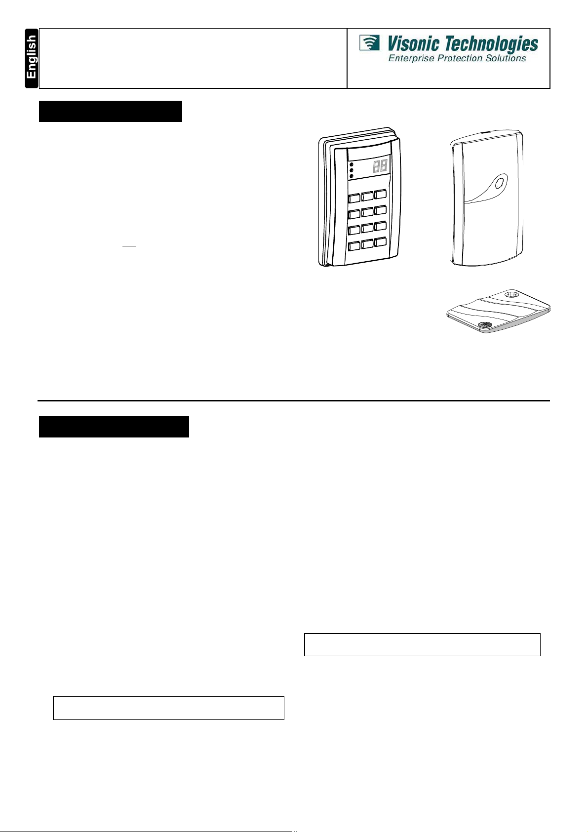
The TIAB (Tag-in-a-Bag) is a versatile weather-resistant proximity
access control unit (fig. 1), designed to limit access to restricted
areas, while permitting authorized people to enter. This product is
the best in its class - using state-of-the-art proximity (non-contact)
RF/ID technology. It was designed to serve your customers’
needs, while making installation and use simple and easy.
The TIAB control unit includes a keypad with an internal proximity
reader and a display that provide full access control operation.
The TIAB control unit can be programmed to offer one of two
security levels for opening the door:
• Level 1 (default): Valid tag only.
• Level 2: Valid tag and
code.
The TIAB control unit transmits 125 kHz RF signal. A valid
proximity tag (fig. 3), presented to the control unit or to the
optional external reader (fig. 2), transmits a coded RF signal back
to the TIAB control unit, causing it to energize an output relay.
The optional external reader is designed for installations in which
an additional reader is required. It is connected to the TIAB
control unit via 4 wires.
The TIAB control unit is installed adjacent to the secured door’s
frame. It is connected to the door’s EMS (Electro-Magnetic Strike)
or magnetic lock and operates by either a 12V DC or AC power
supply. The TIAB control unit includes internal non-volatile
memory, unaffected by power failure. The internal memory stores
data of up to 250 tags and PIN codes (used for security level 2
only). Each PIN is composed of 4 digits.
PIN (Personal Identification Number)
Figure 1. TIAB Keypad Figure 2. RDR-1B External Reader
The proximity tags (fig. 3) are
totally sealed and do not require
any maintenance.
The tags are powered from the RF
signal transmitted from the TIAB
control unit.
In a case of loss or theft of a tag, the tag data can be easily
deleted from the TIAB control unit memory list.
The standard TIAB package includes 10 user tags. Additional
tags are available.
Installation and Programming
Figure 3. TAG-1 Key
2. SPECIFICATIONS
Power input: 12-16V DC or 9-12V AC
Max. Current Consumption: 200 mA (excluding EMS current).
Operating temperature: -20°C to 50°C (-4°F to 122°F).
TIAB CONTROL UNIT
Display: 2 x 7 segments and 3 LEDs.
Buttons: 12 (numeric keypad).
Memory capacity: 250 tag codes.
Tag reading range: 50 - 100 mm (2 -4 in.)
Internal tag reader frequency: 125 kHz.
Tag codes possibilities: 10
Inputs:
• Request-to-exit (N.O.), dry contact
• Door position (N.C.), dry contact
Outputs:
• Lock relay N.O. / N.C. dry contact, 10A / 28V AC or DC
• Door ajar / door held open (open collector output),
100 mA max.
• Panic (open collector output), 100 mA max.
• Auxiliary (open collector output), 100 mA max.
• Forced Entry (open collector output), 100 mA max.
• Tamper (N.C. dry contact). Tamper switch is designed to
detects attempts to open the unit, or remove it from the wall.
NOTE: The total currents of all active open collector
outputs should not exceed 200 mA.
12
possible combinations.
Size (H x W x D): 122 x 82 x 31 mm (4-13/16 x 3-1/2 x 1-1/4 in.)
Weight: 170 g (6 oz) without the rubber gasket
Color: Metallic brown
TAG-1 PROXIMITY TAG
Size (L x W x D): 53 x 35 x 7 mm (2-1/8 x 1 3/8 x 9/32 in.)
Weight: 5.5 g (0.2 oz).
Color: Black
TAG-10: Package of ten TAG-1 proximity tags
RDR-1B EXTERNAL READER (optional)
Indicators: Tri-color LED (green, red, amber).
Tag reading range, tag reader frequency and tag codes
possibilities: identical to Control Unit specification.
Size: (L x W x D): 116 x 70 x 16.8 mm (2 3/4 x 4 1/2 x 5/8 in.)
Weight: 121.5 g (4.3 oz)
Cable (to TIAB control unit) maximum length: 10 m (32 ft.)
TIAB-to-TIAB,
Minimum Distance: 60 cm (2 ft.).
Color: Dark gray
Compliance with standards: Complies with Part 15 of the FCC
Rules and RSS-210 of Industry and Science Canada. Operation
is subject to the following two conditions: (1) This device may not
cause harmful interference, and (2) this device must accept any
interference received, including interference that may cause
undesired operation.
RDR-1B-to-TIAB and RDR-1B-to-RDR-1B
DE6260 1
Page 2
3. MOUNTING
r
(op
)
per
)
(
k
)
A. Remove the case closure screw.
B. Insert a screwdriver in the bottom recess of the base, and
use it to separate the base from the keypad assembly.
C. Place the base on the installation surface, mark the drilling
points, drill the holes and insert plastic anchors, if necessary.
D. Fit the base into the rubber gasket and use the 3 mounting
screws to attach the base and gasket to the selected surface
CAUTION! If you are installing several TIAB units or TIAB
with RDR-1B, locate units at least 60 cm (2 ft) apart.
Attention! The Tamper
switch is activated when the
TIAB control unit’s front
cover is removed or when
the base is forcibly pulled
from the mounting surface,
which causes tamper switch
tab to break (see figure 4).
It is therefore especially
important to firmly attach
this tab to the wall with a
long screw.
Figure 4. Base and Rear Gasket
IMPORTANT! Do not install the RDR-1B on a metal surface or a metal door frame, since this decreases the read range significantly.
If you have to install the reader on a metal surface, use a spacer so that the reader will be at least 1 cm (3/8 in.) away from the metal.
You may use RDR-BACK which is an optionally available spacer designed specifically for this purpose.
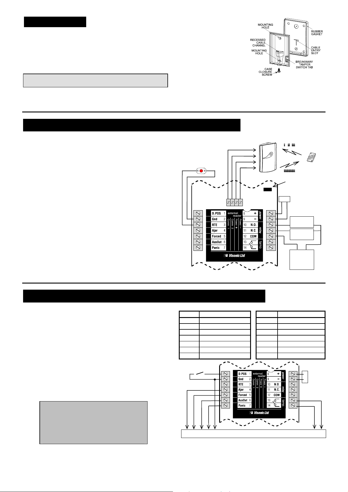
4. WIRING INSTRUCTIONS FOR ACCESS CONTROL
4.1 Wiring Gauges and Routing
Use # 20 AWG or larger for connections between relay and door
strike or other switching devices. All other connections can be
made with # 22 AWG or larger. Route the wires through the slot
in the rubber sealing gasket (see figure 4) and the recessed entry
channel in the TIAB control unit base. Verify that there is no
contact between uninsulated wires and the printed circuit board.
4.2 Wiring Instructions
The connections to the TIAB terminal block are shown in fig. 5.
A. Connect one lead of the door strike to one of the hardware
(door strike) power supply terminals. Connect the other lead
of the door strike to terminal No. 10 (N.O.) of the TIAB.
Note: If you are using a magnetic door lock, connect one of
the leads to one of the hardware power supply terminals.
Connect the other lead to terminal No. 11 (N.C.) of the TIAB.
B. Connect the other power supply terminal to terminal 12 (COM).
C. Connect the TIAB power supply leads between terminals 8 (+)
and 9 (-). When using DC power supply, verify proper polarity.
When using AC power supply, disregard polarity.
D. Connect the optional remote Request-To-Exit push-button
(N.O.) or PIR motion detector contacts (N.O.) across terminals
3 and 2.
Note: For the external reader wiring and mounting instructions,
refer to the external reader installation instructions.
External Reade
tional
Request To Exit
push-button or
motion detector
(N.O.)
COMM 1 (white)
COMM 2 (green)
POWER + (red
POWER –
blac
Figure 5. Wiring Diagram for Access Control
Coded RF
{ {
Personal
Master Reset
Jum
12V DC or AC
power supply
Door strike
or relay
Magnetic
door lock
Door lock
power
supply
(DC or AC)
Tag
5. WIRING FOR INTEGRATION WITH AN ALARM SYSTEM
The integration with an alarm system is shown in figure 6.
A. Perform steps A to D in section 4.2.
B. Connect the Panic output (terminal 7), the AuxOut output
(terminal 6), the Door Ajar output (terminal 4) and the Forced
Entry output (terminal 5) to the appropriate zone of the alarm
system, or to any other indicating device (relay, LED, buzzer,
etc.). All these outputs are of the open collector type (see
figure 7).
C. Connect the Ground (terminal 2) to the alarm system
ground terminal.
D. Connect the Tamper terminals (13 & 14) to a 24-hour
zone of the alarm system.
E. Connect the optional Door Position detector (N.C.
magnetic switch), between terminals 1 and 2.
Caution!
When operating the TIAB control unit by AC
power, disregard polarity, but note that
external buzzers (which are connected to the
AuxOut or Panic outputs) require a separate
DC power supply, as shown in figure 8.
2 DE6260
Table 1 - TIAB Control Unit Terminal Assignments
Terminal Description Terminal Description
1 Door Position input 8
2 Ground output 9 - V power supply
3 Request-To-Exit input 10 Output relay N.O.
4 Door Ajar output 11 Output relay N.C.
5 Forced Entry output 12 Output relay COM
6 Auxiliary output 13 Tamper Switch
7 Panic output 14 Tamper Switch
Door position
detector (N.C.)
{
power supply
12V DC
{{
or AC
{
power
supply
Alarm system
Figure 6 . Wiring Diagram for Integration with an Alarm System
Page 3

Figure 7 - “Open collector” Output Connection to an Alarm System
r
−
Notes:
1. The TIAB and the Control Panel must have a common ground.
2. The Control Panel must be a common negative panel - the
common / shared terminals between zones are 0V (-).
9 (-)
AUX (6) or PANIC (7)
TIAB
Figure 8 - External Buzzer Connections to AuxOut or Panic
Output When TIAB is Powered by AC Power Supply
External
buzze
12VDC
power
+
supply
6. PROGRAMMING
6.1 General Description
The TIAB control unit recognizes a single 4-digit master code
which is used for all programming modes. This code
accompanies a tag which is defined as the master tag.
When first powering-up the Tag-in-a-Bag™ system:
If the display blinks “00” and the green LED flashes, present a
tag close to the keypad. When the display shows “Cd”, enter a
4-digit PIN code and press “#”. This defines the presented tag
as a Master-tag, used for programming. Then proceed to
program the system (Section 6.3).
Reprogramming can be done as many times as necessary, but
for security reasons it is restricted to the master tag holder.
Important:
1. The person in charge must have an updated list which
includes up to 250 tags holders names and the PIN code
assigned to each of the tags. The table attached to the
TIAB User Guide may be used.
2. The master tag should be used for programming only and
must be kept in a safe place!
An existing code must be deleted first if a new code is to be
saved in the same memory address.
Note: The TIAB control unit reverts to normal mode after a 30
second non-activity timeout, or if “
While waiting for the programmer’s selection, the internal buzzer
continuously sounds short beeps.
6.2 Master Tag Programming
Remove jumper Buzzer beeps and stops
Reinstall jumper
Important! The TIAB control unit does NOT operate unless a
valid master tag and master code have been programmed.
A. Remove the Master Reset Jumper (fig. 5). The TIAB buzzer
will start beeping.
B. Once the buzzer stops beeping, re-install the jumper and,
within 10 seconds, key in the master code “8422” followed
by “#”. As a result, the TIAB control unit will go into the
ADD mode (blinking green LED) and and will display the
master code memory address - flashing “00”.
C. Place the tag, assigned as the master tag, within range of
the keypad. The buzzer will beep twice and the display will
show “Cd” (Code).
D. Key in the desired master PIN code (4 digits) and then
press “#”. The programming of the master tag code is
completed and the unit returns to normal position.
→
)
6.3 Entering/Quitting the Programming
Mode
Note: For programming, the master tag and PIN code are
always required, regardless of security level setting.
Entering the Programming Mode
Hold the master tag near the TIAB for at least
10 seconds. After the yellow LED blinks and
the buzzer sounds, key the master tag’s 4-digit
PIN code. “Pr” (Programming) will blink in the display.
” is pressed.
8422
#
)
PIN code
#
Quitting the Programming Mode
Press “” to exit any of the programming mode options into
the main programming mode. Press “” again to quit the main
programming mode and revert to normal operation.
TIAB’s Programming Modes Description
Mode Mode Name Functions Indicator
1 ADD (tags) Adding user tag Green
2 REVIEW (codes) Viewing users codes Red
3 DELETE (tags) Deleting user tags Yellow
4 SETUP Modifying system parameters All LEDs
6.4 Adding User Tags
Security level 1:
Security level 2:
For detailed description, refer to the user’s guide, section 3.1.
“Pr” mode
“Pr” mode
1
) )
) )
1
#
PIN code
6.5 Reviewing User Tags
“Pr” mode
For detailed description, refer to the user’s guide section 3.2.
)
2
6.6 Deleting an Existing User Tag
“Pr” mode
or
“Pr” mode TAG Address
For detailed description, refer to the user’s guide section 3.3.
Note: Deleting information in address 000 invalidates the master
tag. For re-programming the master tag, refer to section 6.2.
)
)
)
# 3 #
# # 3 #
6.7 Setup Mode
Setup mode enables to determine how the TIAB reacts in various
situations. In programming mode (“Pr” is displayed) press “4” to
select the functions setup mode. All the 3 LED’s continuously
blink and the display is blank. In this state, the installer can select
one of seven functions to modify the setup, as detailed in the
function setup table.
Programming steps in the SETUP mode:
“Pr” mode
A. Press the number that corresponds to the desired function (1-7).
B. The TIAB control unit displays the two letters corresponding to
the function (see functions setup table).
C. Press “#” to enter the functions selection mode.
D. The TIAB control unit displays the current value for the
selected function.
E. To accept the existing value, press “#”. To return to the
function setup selection, press “”. To change the existing
value, enter the new value followed by pressing “#”.
4 #
) )
# Function 1-7
New value
#
DE6260 3
Page 4

Table 2 - Function Setup Table
Func. Description Enter Default Display
1 Door unlock duration or toggle
mode (see note 3).
2 Door Position input. Set Door
Ajar alarm timeout of opened
door to 01-99 seconds or
disable (00) - see note 6.
3 Auxiliary Output.
(see notes 1, 6 and table 3).
4 Ambush Digit - Fifth digit
entered after PIN code for
signaling a duress situation.
(see notes 2, 6)
5 Security Level (see notes 4, 5)
1 = No PIN code required.
2 = PIN code is required.
6 Buzzer feedback control.
0= No buzzer feedback.
1= Buzzer beeps when button
is pressed.
7 Buzzer's Indication that the
door is left open.
0 = No buzzer operation.
1 = Buzzer beeps if door is left
open longer than defined in
function 2.
01-98 sec.
99 = toggle
mode
01-99
seconds
00 = disable
door input
0 - 7
0-9
00 = disable
1 or 2 1
0 or 1 1
0 or 1 0
sec.
05
00
0
00
Notes:
1. If the Auxiliary output is enabled, it operates for all tags.
2. Ambush Digit is applicable for security level 2: Ambush Digit is
the fifth digit added to the user PIN code. If the user is forced
to enter under threat, pressing the Ambush digit after the last
digit of the PIN code activates the Panic output.
3. In the Toggle mode, presenting a valid tag/code turns the
output on and presenting it again turns the output off.
4. When selecting security level 1 (no PIN code required) it is still
possible to enter a PIN code for each tag, during
programming. However, in normal operation the TIAB will not
prompt the user for the PIN code.
5. Selecting security level 1 does not affect the master tag. The
master tag always requires a PIN code.
6. Disabling a function by 00, will show
− −
on the display.
IMPORTANT! If you are not using a door position detection
switch, be sure to set “dP’ to “00” and “Ob” to 0. This will
prevent a continuous “Door Ajar” alert.
Table 3 - Auxiliary Output Modes
Setting Auxiliary Output Description
0 Disabled.
1 Triggered for 1 second.
2 Toggled (latch/unlatch).
3 Operated together with relay timer (function 1), but
stays on for 5 seconds more. If toggle mode has been
selected (function 1 - see table 2), the auxiliary output
does not change state each time the relay is toggled.
4 Latches when a valid tag is presented and resets by
pressing “”.
5 Turns on for 10 seconds, by pressing any button.
6 Triggered after 3 consecutive invalid keys are
presented or 3 consecutive invalid PINs are entered.
The output is triggered once a second for 10 minutes
and may be reset only by entering a user code no
sooner than 30 seconds after being tripped.
7 Turned on by pressing “1” and “3” simultaneously.
7. SYSTEM NORMAL OPERATION AND FUNCTIONAL TEST
7.1 Normal Operation
Normal operation is the mode in which the door lock is opened
when a valid tag is presented to the reader (in security level 2,
followed by valid user PIN).
The TIAB control unit can use the internal reader or an optional
external reader to read proximity tags.
Pressing “” and “#” simultaneously activates the Panic output
for 5 seconds. In this case, the buzzer does not beep.
The LEDs functions in normal operation are summarized in the
next table.
LEDs functions in normal operation
LED Function
GREEN Indicates that the door is opened.
{
RED Indicates that an invalid tag was presented or an invalid PIN
{
YELLOW
{
Time Out
A delay of more than 5 seconds, between presenting a tag and
starting to key user PIN code, or between any two digits, cancels
the operation.
If you enter three consecutive wrong codes, the TIAB control unit
will be disabled for 30 seconds and the buzzer will beep rapidly.
This device complies with the essential requirements and provisions of Directive 1999/5/EC of the European Parliament and of the Council of 9 March 1999 on radio and
telecommunications terminal equipment..
was entered.
Remains lit to indicate that the power is on. In security level
2, blinks after a tag is accepted, to prompt the user for PIN.
7.2 System Functional Test
A. Supply power to the TIAB control unit and verify that the
yellow LED lights steadily, to indicate that the power is ON.
B. Enter the TEST mode (see section 4 of user’s guide) and
verify proper function of the TIAB keypad, display and buzzer.
For security level 1 only
C. Present a valid tag at a distance of 50 - 100 mm (2 - 4 in.)
from the keypad (or external reader) and verify that all the
functions are performed as programmed. Verify also that
when the door is opened the green LED is illuminated.
D. Verify that when an invalid tag is presented the buzzer
sounds and the red LED illuminates.
For security level 2 only
E. Present valid tag at distance of 50 - 100 mm (2 - 4 in.) from
the keypad (or external reader).
F. Verify that the yellow LED light starts blinking after tag
presentation, to prompt the user to enter PIN code.
G. Enter the user code followed by the ambush digit. The PANIC
output should be activated, if ambush option is enabled.
H. Verify that when presenting an invalid tag, entering an invalid
code, or both, the red LED illuminates and the buzzer sounds.
For both security levels
I. Verify that all the user tags enable the opening of the door.
J. Verify that pressing “” and “#” simultaneously activates the
panic output for 5 seconds.
VISONIC TECHNOLOGIES. (ISRAEL): 30 Habarzel St. Tel Aviv 69710 ISRAEL Tel 972-3-7681400 Fax: 972-3-7681415 E-MAIL: support@visonictech.com
VTA (VISONIC TECHNOLOGIES AMERICAS): 65 West Dudley Town Road, Bloomfield CT. 06002-1911 USA. TEL.: (860) 243 0833, (800) 223 0020
FAX: (860) 242-8094.
E-MAIL: usa_support@visonic.com
VT UK (VISONIC TECHNOLOGIES UK): Fraser Road, Priory Business Park, Bedford MK44 3WH ENGLAND. TEL.: 44-870-730-0840; FAX: 44-870-730-0839
INTERNET: www.visonictech.com
4 DE6260
Page 5

VISONIC TECHNOLOGIES LTD. 2004 TAG-IN-A-BAG DE6260- (REV. 3, 10/04) Refer to warranty statement in the User Guide.
DE6260 5
 Loading...