

Visonic SRN-2000 SERIES Installation Instructions Manual
DE1200 1
SRN-2000 SERIES
Professional All Purpose PIR Detectors
Installation Instructions
1. INTRODUCTION
1.1 Applications
The SRN-2000 is the only universal PIR you can truly standardize on
without compromising. It combines several different design techniques
to master the industry’s biggest problem - false alarms.
An outstanding variety of 45 easy-to-change lenses is available for the
SRN-2000 from the "Super Red Lens Library":
• 9 wide-angle lenses up to 140° • 3 long-range corridors up to 36 m
(120 ft) • 6 pet alleys • 3 finger curtains • 8 lenses for combined ceiling
and room coverage • 10 unique lenses for multiple 2-3 room and
corridor coverage • 6 solid curtains.
The "Super-Red Lens Library" provides the most extensive selection of
coverages and saves you time and money in every installation.
1.2 Features
Incomparable Flexibility:
• 30° Vertical and Horizontal Adjustments
• 0-5 m (0-17 ft) Installation Height
• Visible Pattern Locator
• Surface, Corner and Flush Mounting
• Switchable Walk-Test Indicator
• N.C. Silent Relay
• Tamper Switch
• Low Current Drain: 17 mA
• 9-16 VDC Supply Voltage
False Alarm Immunity:
• Programmable Pulse Counter - to virtually
eliminate environmental disturbances
• Adjustable Coverage Range - to adjust
coverage range to room size
• Unprecedented RF Immunity - rejects RF
interference up to 1000 MHz
• Light Rejection Filter - rejects visible light
variations
Figure 1. General
View
• Maskable Lens Patterns - to block thermal disturbances
• Test-Point - to identify and eliminate background disturbances
• Dual-Element Low-Noise Pyroelectric Detector - rejects thermal
variations with maximum signal-to-noise ratio.
Additional features are available with other models (see Para. 3.1).
2. SPECIFICATIONS
OPTICAL
Standard Lenses: SRN-2000 Lens No. 100
SRN-2000H Lens No. 52
SRN-2000R Lens No. 55
Interchangeable Lenses: See SUPER-RED Lens Library
Adjustment: Vertical:+10
° to -20° calibrated scale.
Horizontal: up to 30
°
ELECTRICAL
Voltage: 9 to 16 VDC
Current: 20 mA
Relay output: Normally Closed (fail safe) contacts. 18 ohm resistor in
series with contacts. Rating - 0.1 A resistive/30 VDC.
Alarm period: 2-3 seconds
Tamper contacts: Normally Closed, 0.5 A resistive/30 VDC
LED: Walk Test - (switchable)
Testing: Background noise test point
Detector: Dual-element low-noise pyroelectric detector
Coverage-Range Control: Adjustable from 100% to 50% of the
nominal lens coverage range.
Pulse Counter: Programmable to 1, 2 or 3 pulses with self-adjusting
walk-test override.
MOUNTING
Wall or corner mounting. Optional bracket SRF-201 for flush mounting.
ENVIRONMENTAL
Operating temperature: -10
°C to 50°C (14°F to 122°F).
Storage temperature: -20°C to 60°C (-4°F to 140°F).
RFl Protection: No alarm when tested on 21 different frequencies from
20 to 1000 MHz with 20 Watts radio transmitter at 1.2 m (4 ft) distance
or 124 Watts at 3 m (10 ft) distance (corresponds to field strength of 20
V/m).
PHYSICAL
Dimensions: 70 x 120 x 48 mm (2.7 x 4.7 x 1.9 in.)
Weight: 140 g (4.5 oz).
Colors: white.
3. MODELS AND LENSES
3.1 Super Red SRN-2000 Models
SRN-2000: Standard model, with pulse counter.
SRN-2000H: Horizontally mounted PIR provides the largest solid curtain
coverage 18 x 18 m (60 x 60 ft) and five interchangeable lenses (see
Lens Library).
SRN-2000R: Ceiling mounted PIR provides maximum 6 x 18m (20 x 60
ft) floor coverage when mounted at 6 m (20 ft) height.
SRN-2000M: Similar to SRN-2000, but with additional alarm latching
memory for multiple PIR installation on a single zone.
SRN-2000C/PC: 9 Volt battery-operated PIR, providing the lowest
standby current drain - 0.004 mA. Has a pulse counter and is designed
to operate with virtually all wireless transmitters on the market.
SRN-2000CH: Horizontally mounted, battery-operated PIR, providing
same solid curtain patterns as SRN-2000H.
SRN-2000CR: Ceiling mounted, battery-operated PIR, with the same
coverage pattern as SRN-2000R.
SRN-2000W/PCN: Self-contained fully supervised wireless PIR, with
built-in RF transmitter.
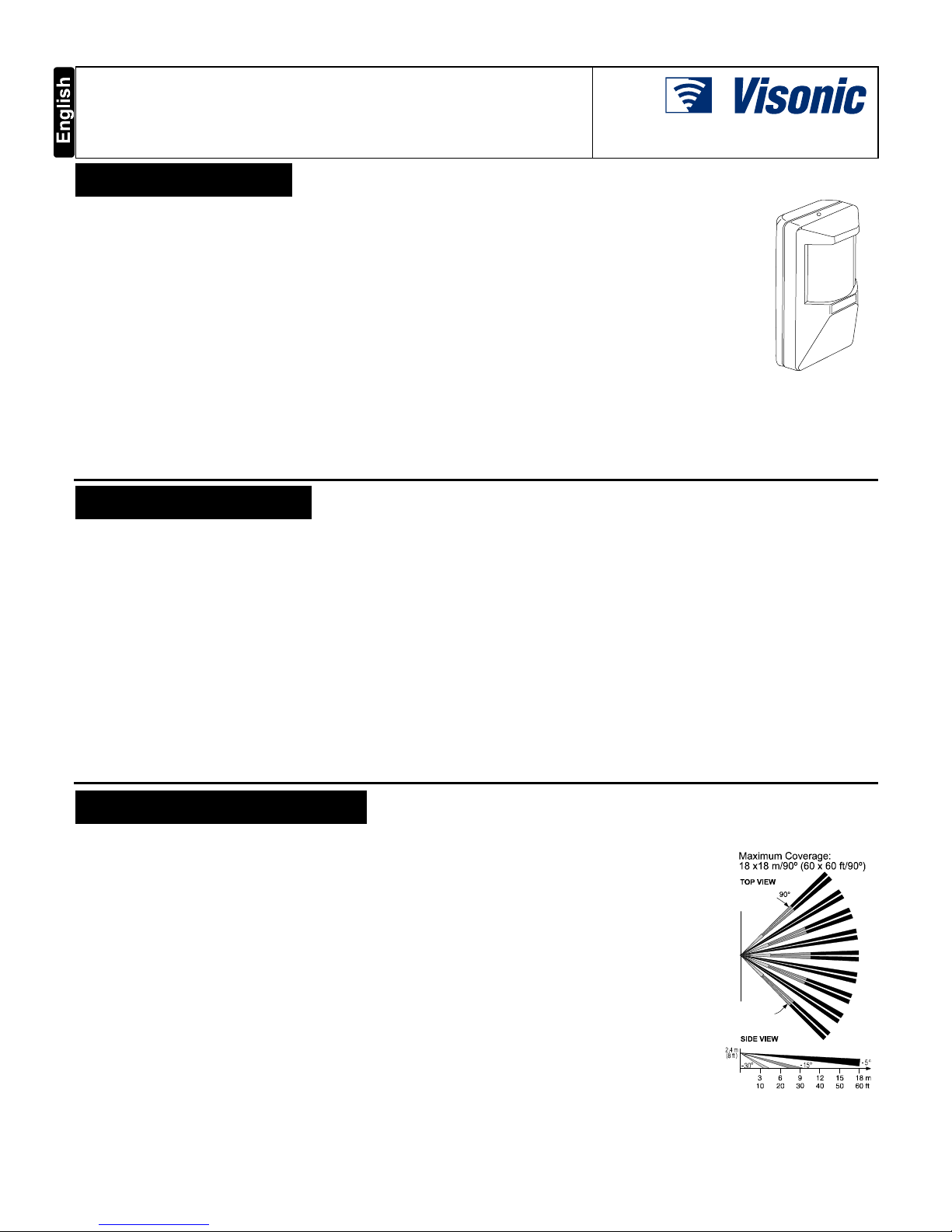
3.2 Lens Selection
Coverage: Lens # 100 is the standard
pattern supplied with SRN-2000
sensors (not applicable to models SRN2000H, R, CH, CR).
Printed circuit board elevation scale is
factory preset at -5
°
. For application of
PCB elevation scale, see Table 1.
Lens No. 100 Specifications
Total Number of Beams: 38
3 Layers: Upper, Intermediate and
Downward. Upper Layer - 9 twin
beams, optically split to 18 beams.
Intermediate Layer - 5 twin beams
(split), angled 10° below upper layer
Downward Layer - 5 twin beams
(split), angled 25° below upper layer.
Angle span: 90° Wide Angle.
Coverage: Max. 18 x 18 m (60 x 60 ft).
Figure 2. Coverage
Pattern - Lens No. 100
If the standard No. 100 lens does not meet your coverage needs, select
the desired pattern from the SUPER RED LENS LIBRARY. Your
nearest distributor will be glad to supply you with any lens you choose.
2 DE1200
LENS LIBRARY
SUPER-RED offers a selection of more than 45 lenses to provide the
best coverage pattern for any installation. The SUPER-RED LENS
LIBRARY is divided into the following nine sections:
Section 1: Corner Mounting Wide-Angle 90° - 100°.
This section comprises 6 lenses which provide the maximum room
coverage, when the PIR is installed in the corner.
Section 2: Ultra-Wide-Angle 120° - 140°.
This section comprises 3 lenses which provide the largest and widest room
coverage in applications where the PIR is wall mounted or flush mounted.
Section 3: Pet-Alleys.
This section comprises 6 lenses with a single horizontal beam layer
which allows pets to move under the coverage pattern, undetected.
Section 4: Long-Range Corridors up to 36 m (120 ft).
This section comprises 3 lenses specially designed for long range and
narrow areas such as corridors, aisles and long walls.
Section 5: Multiple Room and Corridor Coverage.
This section comprises 10 lenses, each providing a combination
coverage of one or two Long-Range corridors and one or two WideAngle rooms simultaneously, using a single PIR.
Section 6: Combined Ceiling, Stair and Room Coverage.
This section comprises 8 lenses providing multiple coverage of ceiling
and stairs in addition to the normal room area coverage.
Section 7: Finger Curtains.
This section comprises 3 lenses providing coverage of multiple vertical
finger curtains which may be used to prevent access from two walls
simultaneously and detect movement through curtains located in the
area between the walls.
Section 8: Lenses for Energy Management PIRs.
This section comprises 4 high density lenses specially designed for use
with models SRN-2000E, ET and EF in Energy Management
applications.
Section 9: Solid Curtain PlRs.
This section comprises 5 lenses specially designed for models SRN-2000H
and SRN-2000CH, providing various types of solid curtain coverage.
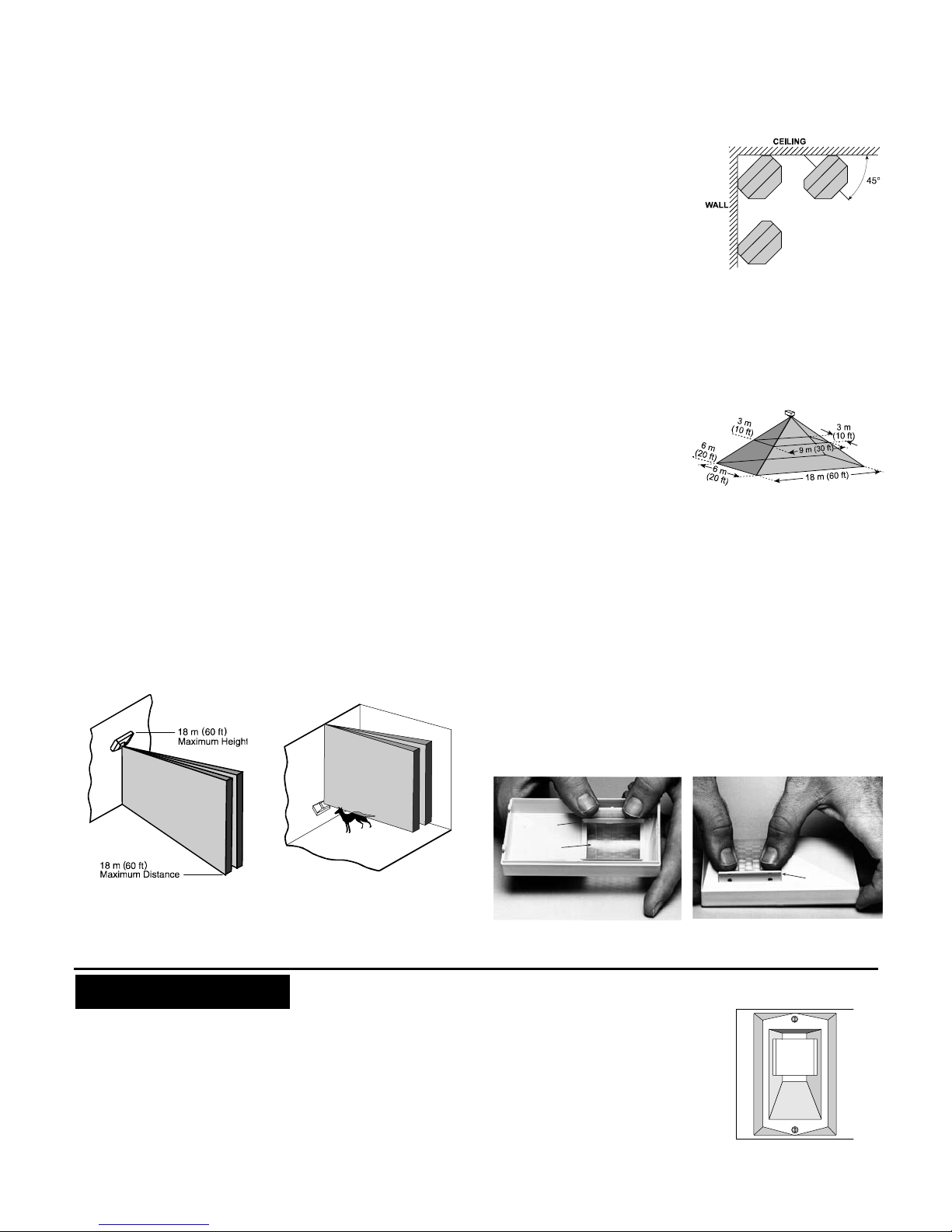
3.3. SRN-2000H Solid Curtain PIR
Description
The SRN-2000H is a horizontally mounted PIR which provides a
variety of Solid-Curtain coverages. The unit may be used to provide
wall and large show window coverage or as an internal invisible
barrier to detect movement between two areas. Lens No. 52 is the
standard lens supplied with SRN-2000H.
Fitted with lens No. 52 this unit produces a solid curtain coverage
extending out from the mounting wall to the opposite wall - up to a
maximum of 18 m (60 ft) and down to the floor (Fig. 3).
Figure 3. Curtain Coverage -
Lens No. 52
Figure 4. Pet-Alley Curtain -
Lens No. 52
A Pet-Alley curtain is created by installing the SRN-2000H near the
floor and angling it 45° towards the ceiling. The height of the curtain
can be adjusted precisely by rotating the lens.
In addition to lens No. 52, several interchangeable lenses are offered,
providing coverage combinations of solid curtains and beams. For
more details refer to SUPER RED LENS LIBRARY.
Mounting
The SRN-2000H should be mounted horizontally on its angular shaped
back, pointing to the floor at a declination of 45°.
The preferred location is at the wallto-ceiling juncture. Wall or ceiling
mounting is also possible as long as
the 45° angle is maintained (Fig. 5).
The unit can be mounted at any
height up to 18 m (60 ft), providing
the largest curtain coverage on the
market - 18 x 18 m (60 x 60 ft). All
lenses, except for No. 52, require
mounting the unit with the lens to the
left (when facing the unit).
Adjustment
The curtain coverage can be adjusted 10° left or right by sliding the
printed circuit board against the graduated scale. Vertical adjustment of
±15° is provided by rotating the lens (applicable for lens No. 52 and 56
only). In other regards, the SRN-2000H is virtually identical to the SRN-
2020.
3.4 SRN-2000R Ceiling Mounted PIR
The SRN-2000R is a ceiling
mounted PIR.
Fitted with lens No. 55, the unit
produces four finger curtains
projected from the ceiling, down to
the floor.
When mounted at the height of
3 m (10 ft), the unit provides a
pattern of 3 x 9 m (10 x 30 ft)
Figure 6.
SRN-2000R Coverage Pattern
maximum (measured at floor level). The maximum recommended
mounting height is 6 m (20 ft) providing a floor coverage area of 6 x
18 m (20 x 60 ft) maximum.
In all other regards, the SRN-2000R is virtually identical with the
SRN-2000H.
3.5 Changing Lenses
To change or adjust a lens, release and remove lens retainers located
on both sides of the lens by pushing them from the inner side of cover
(Fig. 7). Insert a new lens with the grooved surface facing out and the
lens number in the upper right corner.
From inside the cover, carefully center the lens by sliding it right or left,
until it edges protrude equally at both sides.
Holding the lens firmly in place, insert the lens retainers from the front
(ridges pointed outward) and firmly push them into place until a click
is heard (Fig. 8).
LENS
RETAINER
êê
LENS
Figure 7. Lens Retainer
Removal
LENS
RETAINER
êê
Figure 8. Locking the Lens
in Place
4. INSTALLATION
4.1. Selecting the Mounting Location
A SUPER RED passive infrared detector can be mounted directly onto
the wall (surface mounted), or in a corner. It may also be flush mounted,
using optional flush mounting bracket SRF-201 (Fig. 9). Always mount
the unit on a firm and stable surface.
A. Select the mounting location so that the expected motion of an
intruder will cross the beams of the coverage pattern provided by
the lens in actual use.
It is recommended to aim the PIR detector toward the coolest place
in the protected area, in order to obtain the maximum sensitivity
where high ambient temperatures are expected.
B. Select the most convenient
mounting height.
You may mount the unit anywhere
from ground level up to 5 m (17 ft).
An accurate adjustment table determines the recommended angle for
any combination of range and
mounting height (see Table 1).
Take into account that installations
at increased height result in larger
blind areas close to the detector.
Figure 9. Flush mounting
bracket SRF-201
Figure 5. SRN-2000H
Mounting Alternative
 Loading...