

Page 1

MDT
MDT----122
MDTMDT
122
122 122
Response
Man-Down Transmitter
1. INTRODUCTION
1. INTRODUCTION
1. INTRODUCTION1. INTRODUCTION
MDT-122 is an automatic personal security transmitter. This
micro-processor controlled transmitter is designed for use by
guards in a prison, by security officers in an organization or
institution, or by employees in a large industrial complex (as an
industrial signaling device for safety). In areas that 1 person is
not allowed to work alone, MDT-122 can be an excellent solution.
The MDT-122 alarm signal can be received by a compatible
receiver, like MCR-308, and can be integrated in any alarm
system.
MDT-122 is attached to the guard’s pouch / holster.
The transmitter is activated in the following events (see fig. 2):
A. PANIC
When the guard needs help, he presses both
(pressing both buttons is required to prevent an accidental
panic message transmission).
B. MANDOWN
When the guard falls down (automatic transmiss ion when the
unit is tilted down by more than 60
C. PULL-CORD
The pull-cord is attached strongly by a clip to the guard’s belt
on one side and is plugged into the transmitter by an easily
detachable plastic pin on the other si de. Pulling the cord or
the unit away causes the plastic pin to be detached and to
buttons
).
°
User’s Guide
release an internal switch that activates an alarm
transmission. This may happen when an attacker tries to
draw the unit away from the guard or by the holder, in case of
emergency and difficulty to press the twin buttons for alarm.
Pull
cord
Right
push
button
LED
Figure 2 - External View
Temporary
TILT OFF
push-button
Tilt ON/OFF
slide switch
Cover
screw
Left
pushbutton
Vertical (normal)
Position
Figure 3 - Activating the
Internal Tilt Switch
MCR-308
wireless
receiver
OUT
L. BAT
JAMM
Optional
alarm
system
READY
ND
BYPASS
POWER
1
2
4
5
7
8
2
0
CLR
Optional
automatic
dialer
BCD
ARM
HOME
AWAY
3
A
6
B
9
C
ENT
D
2 - CHANNEL
SPEECH DIALER
Model: DL-
AUTOMATIC
PROGRAM
PROG
2
3
1
EF
ALARM-1
AL-1
4 56
ALARM-2
AL-2
789
A-F A
STOP
0#
STOP
DIAL
*
Public
telephone
exchange
Siren
2
3
1
MDT-122
Figure 1 - Integration of MDT-122 in an Alarm System
DE2295U 1
Page 2

2. SPECIFICATIO NS
2. SPECIFICATIO NS
2. SPECIFICATIO NS2. SPECIFICATIO NS
Transmission T ype:
RF frequency (MHz):
Transmitter’s ID Code:
Modulati on type:
Overall Message Length:
Alarm Messages
alarm, each with separate ID
Power Source:
(Tadiran TL-2150 or equivalent.)
Current Consumption:
Battery Life Expectancy:
3. FUNCTIONAL DESCRIPTION
3. FUNCTIONAL DESCRIPTION
3. FUNCTIONAL DESCRIPTION3. FUNCTIONAL DESCRIPTION
Radio Frequency (RF)
433.92
28-bit ID, Code Secure
pulse width modulation
66 bit
: Tilt activated, pull-cord disconnected, Panic
3.6 V, Lithium battery, size 1/2 AA / 1.2 Ah,
15
A standby, 10mA (operation)
µ
Up to 3 years (with regular use)
TM
3.1 Visual and Audible Warning Timing
A built-in tilt sens or activates the unit when the unit is tilted down
by more than 60
enters a pre-alarm state for 30 seconds. This period enables the
user to return the transmitter to t he normal (vertical) position, to
prevent an unintentional alarm transmission.
During this period an audible warning is sounded by the buzzer
and a visual warning is indicated (by the internal LED). The
buzzer’s sound can be disabled by using an internal buzzer’s
switch (see table 1). Figure 4 presents the timing diagram.
MDT-122 is returned to
normal position after 30 sec.
(see figure 3). When the unit is activated, it
°
MDT-122 is returned
to normal position
before 30 sec.
Battery Supervision:
Operating temperature:
Dimensions
With Holster-3: 140 x 77 x 50 mm (5-7/16 x 3-1/16 x 1-15/16 in.)
Housing:
Weight:
Color:
Complian ce with Std .:
Accessories:
Metal belt clip.
Pull-cord with pin and cloth clip.
B. Tilt ON-OFF Slide Switch
By using this switch, the user can disable the tilt sensor
function (this is necessary when a guard goes off duty or
performs such activiti es that can activate the transmitter and
create a false alarm). When the unit is delivered from the
factory, the switch is in OFF position.
C. Temp Tilt Off Push-Button Switch
The push-button is located at the top of the unit. It is used for
temporary
when it is desired. To re-enable tilt function before the 5
minutes delay expires, the tilt ON-OFF slide switch should be
switched to OFF position and then to ON again.
(H x W x D): 120 x 52 x 36 mm (4-3/4 x 2-1/16 x 1-5/16 in.)
3mm ABS plastic box, weather proof
Man-down -138 g (4.9 Oz.), Holster-3 - 30 g (1.05 Oz.)
Body - dark gray , buttons - brown, pull cord - black
3.4 Pull-Cord Function
Battery test every hour
0
C to 49°C (32°F to 120°F)
°
FCC Part 15
Light weight water-resistant carry pouch Holster-3.
disabling (5 minutes) of the tilt sensor function,
(see par. 1C)
Buzzer
sound
ON
OFF
Transmission
and LED
ON
OFF
Prealarm time:
15 short beeps
+ 1 long beep
030
Alarm
restore
Alarm
030
Figure 4 - MDT-122 Functiona l Timing Diagram
Part of
prealarm time
030
t (sec.)
t (sec.)
3.2 Low Battery Voltage Indication
The battery is automatically tested every hour, under load
condition. If the battery voltage is low, “low battery” message is
sent every transmission.
In addition, when the battery voltage is low, the LED blinks while
pressing the left or right push-button switch.
3.3 External Buttons Functions
A. Left or Right push-buttons
When left and
transmitted.
right push-buttons are pressed, panic alarm is
(see fig. 2)
3.5 Internal DIP Switches Functions
Table 1 - Internal DIP Switches Functions
Switch Description Default
1 Buzzer ON/OFF ON
2 Pull-cord op tion ON
3 (not used) OFF
4 (not used) OFF
5 (For future use) 6 Tilt alarm del ay ON/OFF (*) ON
*
Tilt Alarm Delay Enable/Disable
30 second pre-alarm delay enabled/disabled.
If the “tilt alarm delay” DI P switch is set to OFF position (no
delay) the tilt pre-alarm DIP switch position is dis regarded.
3.6 Buzzer Functions
The internal buzzer sounds, as shown in figure 4 and in the
following situations:
When someone is tampering / stops tampering with the unit.
A.
Whenever the internal DIP switch setti ng is changed.
B.
2 DE2295U
Page 3
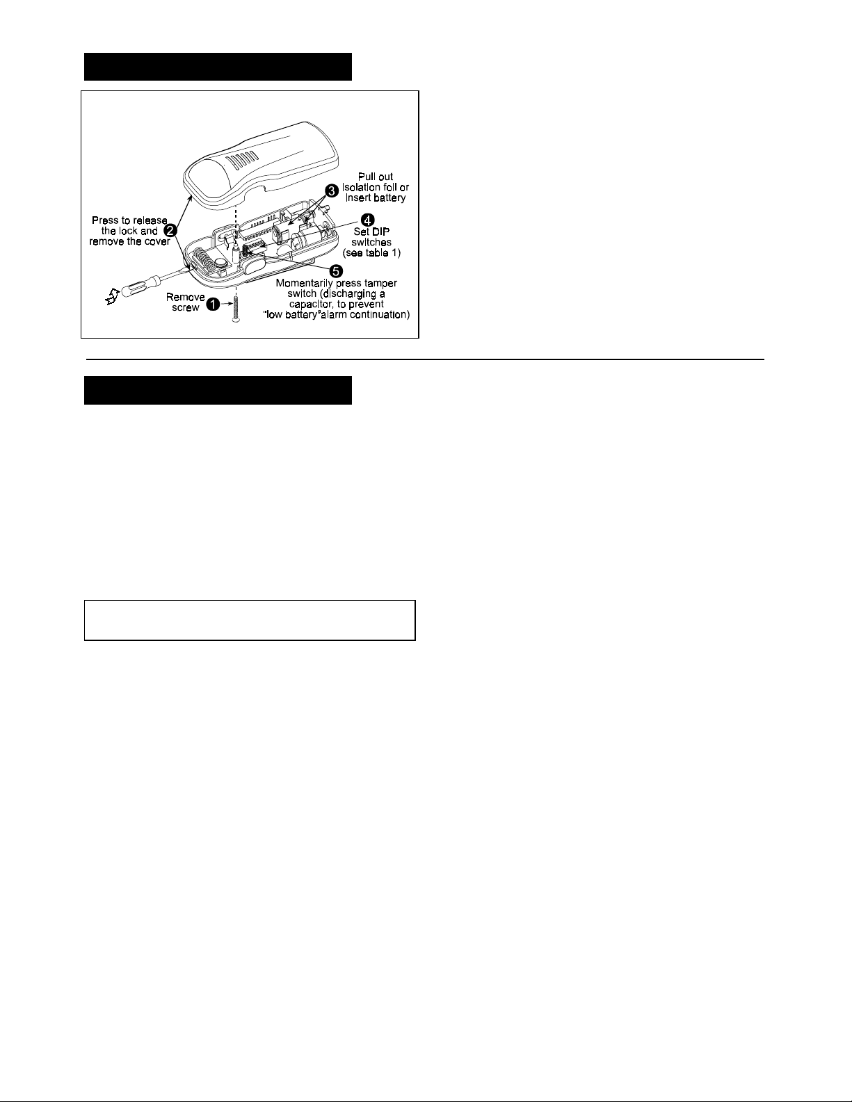
4. PREPARATION FOR USE
4. PREPARATION FOR USE
4. PREPARATION FOR USE4. PREPARATION FOR USE
4.1 MDT-122 Preparations for Use
5. NOTES AND WARNINGS
5. NOTES AND WARNINGS
5. NOTES AND WARNINGS5. NOTES AND WARNINGS
Figure 5 - Preparation for Use
4.2 Teaching the Target Receiver
It is recommended to use the MDT-122 with MCR-308 as a target
receiver (for other receiver types, see section 1). Each of the
three MDT-122 alarm types (Panic, Man-Down, Pull-Cord)
activates a different MCR-308 output, to provide any desired
function, like sounding a siren or activating an automatic dialer
(for delivering a prerecorded voice/digital message to
predetermined addresses).
To provide the desired alarms, the target receiver must “learn” to
identify the Man-down transmitter t ransmission. For the learning
process, refer to the relevant receiver installation instructions
document. If MCR-308 is used as a target receiver, refer to
document DE3191, paragraphs 3-5 and 3-7 to 3-9.
4.3 Test
Simulate all the act ions t hat are shown in figure 4 and veri fy that
proper buzzer, LED and transmissions functions are performed.
5.1 Product Limitations
ResponseLink wireless systems are very reli able and are tested
to high standards. However, due to low transmi tting power and
limited range (required by FCC and other regulating authorities),
there are some limitations to be considered:
Receivers may be blocked by radio signals occurring on or
A.
near their operating frequencies, regardless of the digital code
used.
Wireless equipment should be tested regularly to determine
B.
whether there are sources of interference and to protect
against faults.
5.2 Compliance with Standards
WARNING!
approved by the party responsible for compliance could void the
user's authority to operate the equipment.
Changes or modifications to this unit not expressly
The 433.92MHz version complies with FCC Rules Part 15.
Operation is subject to two conditions: ( 1) This device may not
cause harmful interference, and (2) this device must ac cept any
interference that may be received or that may cause undesired
operation.
The product has been tested and found to comply with the limits
for cla ss B digi tal devic e, pursua nt to part 15 of the FCC Rules .
These limits are designed to provide reasonable protection
against harmful interference in a residential installation. This
equipment generates, uses and can radiate radio frequency
energy and, if not used in accordance with the instructions, may
cause harmful interference to radio communications. However,
there is no guarantee that the interference will not occur in a
particular installation
DE2295U 3
Page 4

WARRANTY
ResponseLink Ltd. and /or its s ubsidiaries and its affiliates ("the Manufactur er") warrants
its products hereinafter referre d to a s "the Pr oduct" o r "Produc ts" to be in c onforman ce
with its own plans and specifications and to be free of defects in materials and
workmanship under n ormal us e and s erv ice for a period of twelv e mon ths fr om the date
of shipment by the Man ufacture r. The Manufacture r's obligations s hall be limited within
the warranty period, at its option, to repair or replace the product or any part thereof. The
Manufacturer sh all not be respons ible for dismantling and/or reinstallation charges . To
exercise the warranty the product m ust be retur ned to the Manufactu rer freight prepaid
and insured.
This warranty does not apply in the following cases: improp er in st allat ion, mis use ,
failure to follow installation and operating instructions, alteration, abuse, accident or
tampering, and repair by anyone other than the Manufacturer.
This warranty is exclusive and express ly in lieu of all other warranties, obligations or
liabilities, whether written, oral, express or implied, including any warranty of
merchantability or fitness for a particular pur pose, or otherw ise. In no case shall the
Manufacturer be liable to anyon e for any co ns e quential or incidental damages for breac h
of this warranty or any other warranties whatsoe v er, as afore s aid.
This warranty sha ll not be modified, varied or extend ed, and t he Manufactur er does not
authorize any person to a c t o n its b eha lf in the mo dification, v ariation or e xte ns ion of this
warranty. This warra nty shall apply to the Product only. All products, ac cessories or
attachments of oth ers use d in conju nction with the Pr oduc t, including batteries , shall be
covered solely by their own warranty, if any. The Manufacturer shall not be liable for any
damage or loss whats oever, whether direc tly, indirectly, incidentally, cons equentially or
otherwise, caused by the malfunction of the Product due to products, acc essories, or
attachments of others, including batteries, used in conjunction with the Products.
The Manufacturer does no t repres ent that its Produc t may not be c ompromised an d/or
circumvented, or that the Produc t will prevent any death, perso nal and/or bodily injury
and/or damage to pro perty res ulting from burg lary, r obbery , fire or ot herwise, o r that the
Product will in all cases provide adequate warning or protection. User understands that a
properly installed and maintained alarm may only redu ce the risk of events such as
burglary, robbery, and fire without warning, but it is not insurance or a guarantee that
such will not occur or that the re will be no death, personal damage and/or d amage to
property as a result.
The Manufacturer shall have no liability for any death, personal and/or bodily
injury and/or damage to property or other loss whether direct, indirect, incidental,
consequential or otherwise, based on a claim that the Product failed to function.
However, if the Man ufacture r is held liable, whether direc tly or indirectly, for any loss o r
damage arising under this limited warranty or otherwise, rega rdless of cause o r origin,
the Manufacturer's maximum liability shall not in any case exce ed the purcha se price of
the Product, which sh all be fixed as liquidated damages and n ot as a p enalty, and sha ll
be the complete and exclusive remedy against the Manufacturer.
Warning: The user s hould follow the inst allation and operation instr uctions and am ong
other things tes t the Pro duct and the whole s ystem at least once a week . For various
reasons, including, but not limited to, change s in environmental conditions, electric or
electronic disruptions and tam pering, the Product may not per form as expected. The
user is advised to t ak e all necessary precau tions for his /her safety an d the protection of
his/her property.
6/91
Response
RESPONSELINK: 9555 SEMINOLE BLVD. SEMINOLE, FL 33772, U.S.A. PHONE: 1-800-894-1428
Internet Web Site: www.responselink.com
MDT-122 , DE2295U (REV. 0, 2/2003).
4 DE2295U
 Loading...