

Page 1
D-300254 1
MCT-241 MD
English
Distress / Fall-detector Transmitter
Español
Transmisor PowerCode™ Detector de Peligro / Caída
ENGLISH
1. INTRODUCTION
The MCT-241 MD is a miniature, microprocessor-controlled personal
UHF transmitter. It is designed to transmit coded alert signals
manually (when the user presses the button) or automatically (when
the user falls down). The transmitter is waterproof and suitable for
wearing in a shower. Operating power is obtained from an internal 3V
CR-2 Lithium battery.
Transmission is initiated in the following cases:
Depressing the recessed oval pushbutton (see Fig. 1). A built-in
timer determines the transmission time to 3 seconds, even if the
user maintains the button pressed shorter or longer than that.
Tilting the transmitter by more than 60° in any direction. In this
case, the 3-second transmission will take place after a 2- second
delay.
When triggered, the MCT-241 MD transmits a unique 24-bit digital ID,
randomly selected in the factory. This code is one of 16 million possible
code combinations and is therefore virtually impossible to reproduce.
The ID code is followed by the appropriate digital marker that indicates
an “alarm” or a ‘fall-detector” event, as the case may be.
A red LED (see Fig. 1) lights steadily during transmission, to reassure
the user that a transmission is taking place and to indicate that the
battery condition is good. If the LED flashes each time the transmitter
is triggered, this indicates that the voltage is low and the battery must
be replaced as soon as possible.
If the transmitter is triggered while the battery voltage is low, a ‘low
battery’ digital marker is included in the transmitted message. In
addition, the battery is self-tested every 12 hours. A supervisory ‘low
battery’ message is transmitted after detection of 3 consecutive “low
battery” states.
The transmitter case is waterproof, hermetically sealed (no screws) and
therefore disposable. Do not attempt to open the transmitter case or
replace the battery; such action will void the warranty.
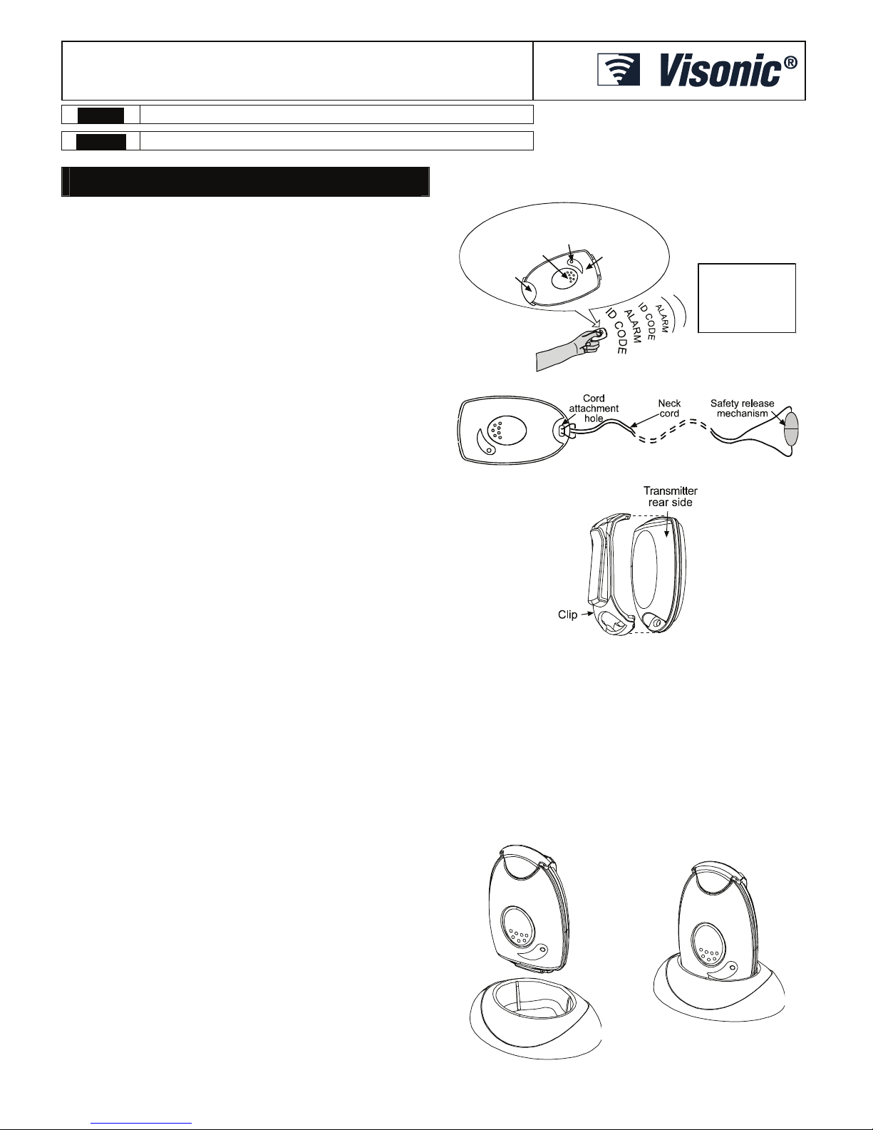
The transmitter is supplied with two wearing accessories, a neck cord
(to be worn around the neck - see Fig. 2) and a clip (to be attached to
the user belt or shirt pocket - see Fig. 3).
The neck cord includes a built-in safety release mechanism. This neck
cord must never be replaced with a cord that does not include a safety
release.
2. OPERATION AND ENROLLMENT
2.1 Transport Mode
New MCT-241 MD units are shipped with the tilt (fall-detector)
function in ‘deep sleep”, to prevent inadvertent transmissions until the
unit is placed into service. To ‘awaken” the tilt function, the alarm
pushbutton must be pressed at least 5 times in succession
.
2.2 Tilt Alarm/Tilt Restore
A built-in tilt sensor is activated once the unit is tilted over by more than
60° in any direction. The Base Unit will notify the user after 30 seconds,
and the actual tilt alarm transmission to the central station will take
place after an additional 30-second delay, throughout which the unit
may be restored to the upright position. This allows the user to prevent
an accidental “tilt alarm” message from being transmitted. If a tilt alarm
had been transmitted and the unit was subsequently returned to the
upright position, a “tilt restore” message will be transmitted.
Note: Please refer to the AMBER user manual for further details on
this feature.
MCT-241MD Transmitter
MCR-304
MCR-308
POWERMAX
MAESTRO 1600
EXP-1600W
Clip
LED
Transmission
pushbutton
Front side
(don’t cover
with hand
during
transmission)
POWERCODE
RECEIVER
OPTIONS
Figure 1 - Using the MCT-241 MD
Figure 2 - MCT-241 MD with Neck Cord
Figure 3 - Clip Attachment
2.3 Low Battery Voltage Indication
The battery is automatically tested under load once in 12 hours. If a
low battery state is registered in 3 consecutive tests, a “low battery”
message will be transmitted, and a “low battery” digital marker will be
included in every transmission, “alarm” or “tilt”. In addition, when the
battery voltage is low, the LED flashes while the pushbutton is
pressed.
2.4 Transmitter Stand
When putting the transmitter away, it is recommended to use the
special stand included in the package (Fig. 5). The stand will maintain
the unit in a vertical (upright) position, thus preventing accidental
activation of the tilt sensor. Place the stand on a flat surface, then
insert the bottom end of the unit into the stand.
Figure 4. Transmitter Stand
Page 2

2 D-300254
2.5 Initial Te st
Upon press of the transmission button, the control panel will sound and
display simultaneously CALLING SERVICE BUREAU… until contact is
established. This means that the transmitter is working properly.
Note: If for any reason the MCT-241 MD does not result in the above
response from the control panel, please contact the central station and
verify the PowerCode ID located both on the unit's package and on the
reverse side of the transmitter.
2.6 Teaching the Target Receiver
To provide the desired response, the target receiver must “learn” to
identify the Transmitter ID code. Advise the Central Station (either by
telephone or by fax) of the Transmitter ID located both on the unit's
package and on the reverse side of the unit.
2.7 Entering Sleep Mode
This feature helps to preserve battery life.
1. Position the transmitter horizontally on an even surface.
2. Press the transmitter's button for at least ten seconds.
3. As soon as the LED starts to blink, remove your finger from the button.
4. Press the button again (short press).
The unit blinks twice indicating that the unit is in sleep mode. The
transmitter immediately becomes operational upon a single press of
the button.
3. SPECIFICATIONS
Frequency (MHz): 868.95, 315, 433 or other frequency according to
local requirements. Stabilized by SAW resonator.
Frequency Tolerance: ± 120 kHz
Modulation: A.S.K (on-off keying)
Encoding: Factory programmed, 24-bit digital word
Transmission Duration: 3 seconds (even if the user keeps the
transmission button depressed shorter or longer than that)
Power Supply: 3 V Lithium Battery, 0.7 Ah Panasonic CR-2 only.
(Battery replacement is performed at the factory.)
Current Consumption: 7 μA (during standby), 10 mA (during
transmission)
Battery Life Expectancy: 3 years (for typical use)
Caution! Risk of explosion if battery is replaced by an incorrect type.
Dispose of used batteries according to the manufacturer's instructions.
Battery Condition Indication and Reporting:
A. Good battery - the LED lights steadily upon transmission.
B. Low battery - when transmission button is pressed, “low
battery” alarm code is transmitted and the LED flashes.
C. Battery supervision - every 12 hours. If 3 consecutive “low
battery” states are detected, a “low battery” message is transmitted.
Operating Temperature: -10°C to 40°C (14°F to 104°F)
Dimensions (H x W x D):
With Clip: 73 x 41 x 30 mm (2-7/8 x 1-5/8 x 1-3/16 in.)
Without Clip: 67 x 41 x 21 mm (2-5/8 x 1-5/8 x 13/16 in.)
Weight: 35 g (with clip), 30 g (without clip)
Color: White
Compliance with Standards: Meets FCC Part 15, MPT1349,
Directive 1999/5/EC and EN 50131-1 Grade 2, Class II
This device complies with the essential requirements and provisions of
Directive 1999/5/EC of the European Parliament and of the Council of 9
March 1999 on radio and telecommunications terminal equipment.
The technical documentation as required by the European Conformity Assessment
procedure is kept at:
UNIT 6 MADINGLEY COURT CHIPPENHAM DRIVE KINGSTON MILTON KEYNES
MK10 0BZ. Telephone number: 0870 7300800, Fax number: 0870 7300801
4. MISCELLANEOUS COMMENTS
4.1 Product Limitations
Our wireless systems are very reliable and are tested to high
standards. However, due to their low transmitting power (required by
FCC, DTI and other regulating authorities) there are some limitations
to be considered:
A. Receivers may be blocked by radio signals on or near their
operating frequencies, regardless of the code selected.
B. A receiver can only respond to one transmitted signal at a time.
C. Wireless equipment should be tested regularly (at least once a
week) to determine if there are sources of interference and to
protect against faults.
4.2 Battery Handling
Since the product has a Lithium battery, please observe the following
handling instructions:
• Do not dispose of batteries in fires
• Do not short circuit
• Observe correct polarity of cells
• Do not crush
• Do not puncture
• Do not open
• Do not dismantle
• Do not expose to temperatures in excess of 60°C
ATTENTION! The internal Lithium battery can be replaced in the
factory only.
4.3 Compliance with Standards
The 315 MHz version of this device complies with Part 15 of the FCC
Rules. Operation is subject to the following two conditions: (1) This
device may not cause harmful interference, and (2) This device must
accept any interference received, including interference that may cause
undesired operation.
WARNING! Changes or modifications to this unit not expressly
approved by the party responsible for compliance could void the
user's authority to operate the equipment.
The digital circuit of this device has been tested and found to comply
with the limits for a Class B digital device, pursuant to Part 15 of the
FCC Rules. These limits are designed to provide reasonable
protection against harmful interference in residential installations. This
equipment generates uses and can radiate radio frequency energy
and, if not installed and used in accordance with the instructions, may
cause harmful interference to radio and television reception.
However, there is no guarantee that interference will not occur in a
particular installation. If this device does cause such interference,
which can be verified by turning the device off and on, the user is
encouraged to eliminate the interference by one or more of the
following measures:
– Re-orient or re-locate the receiving antenna.
– Increase the distance between the device and the receiver.
– Connect the device to an outlet on a circuit different from the one
which supplies power to the receiver.
– Consult the dealer or an experienced radio/TV technician.
WARRANTY
Visonic Limited (the “Manufacturer") warrants this product only (the "Product") to the original purchaser only (the
“Purchaser”) against defective workmanship and materials under normal use of the Pr oduct for a period of
twelve (12) months from the date of shipm ent by the Manufacturer.
This Warranty is absolutely condition al upon the Product having been properly installed, maintained and
operated under conditions of normal use in accor dance with the Manufacturers recommended insta llation and
operation instructions. Products which have become defective for any other reason, accordi ng to the
Manufacturers discretion, such as improper installation, failure to follow recommended installation and
operational instructions, neglect, willful damage, misuse or vandalis m, accidental damage, alteration or
tampering, or repair by anyone other than the manufacturer, are not covered b y this Warranty.
The Manufacturer does not represent that this Product may not be compromised and/or circumvented or that the
Product will prevent any death and/or p ersonal injury and/or damage to propert y resulting from burglary,
robbery, fire or otherwise, or that the Pr oduct will in all cases provide adequ ate warning or protection. The
Product, properly installed and m aintained, only reduces the risk of such events without warning and it is not a
guarantee or insurance that such events wil l not occur.
THIS WARRANTY IS EXCLUSIVE AND EXPRESSLY IN LIEU OF ALL OTHER WARRANTIES,
OBLIGATIONS OR LIABILITIES, WHETHER WRITTEN, ORAL, EXPRESS O R IMPLIED, INCLUDING ANY
WARRANTY OF MERCHANTABILITY OR FITNESS FOR A PARTICULAR PURPOSE, OR OTHERWISE. IN
NO CASE SHALL THE MANUFACTURER BE LIABLE TO ANYONE FOR ANY CONSEQUENTIAL OR
INCIDENTAL DAMAGES FOR BREACH OF THIS WARRANTY OR ANY OTHER WARRANTIES
WHATSOEVER, AS AFORESAID.
THE MANUFACTURER SHALL IN NO EVENT BE LIABLE FOR ANY SPECIAL, INDIRECT, INCIDENTAL,
CONSEQUENTIAL OR PUNITIVE DAMAGES OR FOR LOSS, DAMAGE, OR EXPENSE, INCLUDING LOSS
OF USE, PROFITS, REVENUE, OR GOODWILL, DIRECTLY OR INDIRECTLY ARISING FROM
PURCHASER’S USE OR INABILITY TO USE THE PRODUCT, OR FOR LOSS OR DE STRUCTION OF
OTHER PROPERTY OR FROM ANY OTHER CAUSE, EVEN IF MANUFACTURER HAS BEEN ADVISED OF
THE POSSIBILITY OF SUCH DAMAGE.
THE MANUFACTURER SHALL HAVE NO LIABILITY FOR ANY DEATH, PERSONAL AND/OR BODILY
INJURY AND/OR DAMAGE TO PROPERTY OR OTHER LOSS WHETHER DIRECT, INDIRECT,
INCIDENTAL, CONSEQUENTIAL OR OTHERWISE, BASED ON A CLAIM THAT THE PRODUCT FAILED TO
FUNCTION.
However, if the Manufacturer is held liable, whether directly or indirectly, for any los s or damage arising under
this limited warranty, THE MANUFACTURER'S M AXIMUM LIABILITY (IF ANY) SHALL NOT IN ANY CASE
EXCEED THE PURCHASE PRICE OF THE PRODUCT, which shal l be fixed as liquidated damages and not as
a penalty, and shall be the complete and exclusive remedy against the Manufacturer.
When accepting the delivery of the Product, the Purchaser agrees to the said conditions of sale and warranty
and he recognizes having been inform ed of.
Some jurisdictions do not allow the exclusion or limitation of incidental or consequential damages, so th ese
limitations may not apply under certa in circumstances.
The Manufacturer shall be under no liability whatsoever arising out of the corruption and/or malfunctioning of any
telecommunication or electronic equipment or any programs.
The Manufacturers obligations under this W arranty are limited solely to repair and/or repl ace at the
Manufacturer’s discretion any Produc t or part thereof that may prove defective. Any repair and/or replacem ent
shall not extend the original W arranty period. The Manufacturer shall not be res ponsible for dismantling and/or
reinstallation costs. To exercise this Warranty the Product must be returned to th e Manufacturer freight pre-paid
and insured. All freight and i nsurance costs are the responsibility of the Purchaser and are not included in this
Warranty.
This warranty shall not be modified, varied or extend ed, and the Manufacturer does not authorize an y person to
act on its behalf in the modification, variation or ex tension of this warranty. This warranty shall apply to the
Product only. All products, acces sories or attachments of others used in c onjunction with the Product, including
batteries, shall be covered solely by their own warr anty, if any. The Manufacturer shall not be liable for any
damage or loss whatsoever, whether directly, indirectly, incidentally, consequenti ally or otherwise, caused by the
malfunction of the Product due to products, acces sories, or attachments of others, including batteries, used in
conjunction with the Products. This Warranty is exclusive to the original Purc haser and is not assignable.
This Warranty is in addition to and does not affect your legal rights. Any provision in this warranty which is
contrary to the Law in the state or countr y were the Product is supplied shall not apply.
Warning:
The user must follow the Manufacturer’s installation and operationa l instructions including testing the
Product and its whole system at least once a week and to take all necessary precautions f or his/her safety and
the protection of his/her property.
1/08
Page 3

D-300254 3
ESPAÑOL
1. INTRODUCCION
El MCT-241 MD es un transmisor UHF personal en miniatura
controlado por microprocesador. Está diseñado para transmitir
manualmente señales codificadas de alerta (cuando el usuario
presiona el botón) o automáticamente (cuando el usuario cae). El
transmisor es impermeable y conveniente para ser usado en una
ducha. La alimentación de funcionamiento se obtiene de una batería
interna de litio de 3V CR-2.
La transmisión es iniciada en los siguientes casos:
Presionando el botón ovalado (véase figura 1). Un temporizador
incorporado determina el tiempo de la transmisión a 3 segundos,
incluso si el usuario mantiene el botón de transmisión presionado
durante más o menos tiempo que el establecido.
Inclinando el transmisor a más de 60° en cualquier dirección. En
este caso, la transmisión de 3 segundos empezará después de un
retraso de 2 segundos.
Cuando accionado, el MCT-241 MD envía un ID digital único de 24
bits, seleccionado aleatoriamente en fábrica. Este código es uno de
16 millones de combinación de códigos posibles y es por lo tanto
virtualmente imposible de reproducir. El Código ID es seguido por el
apropiado marcador digital una “alarma” o un evento de “detector de
caída”, cual sea el caso.
Un LED rojo (véase figura 1) se enciende constantemente durante la
transmisión, para asegurar al usuario que la transmisión está siendo
ejecutada y para indicar que la condición de la batería es buena. Si el
LED parpadea cada vez que se activa el transmisor, esto indica que el
voltaje de la batería es bajo y debe ser reemplazada cuanto antes.
Si se activa el transmisor cuando el voltaje de la batería es bajo, una
marcación digital de ‘batería baja’ es incluida en el mensaje
transmitido. Además, la batería es auto-probada cada 12 horas. Un
mensaje de supervisión “batería baja” es transmitido después de
detectado tres estados consecutivos de “batería baja”.
La caja del transmisor es herméticamente sellada (sin tornillos) para
asegurar la completa impermeabilidad de la caja. El reemplazo de la
batería debe ser realizado solamente en fábrica.
El transmisor es proveído con dos accesorios para llevar puesto: un
colgante (para ser usado alrededor del cuello - véase Fig. 2) y un clip
(para ser unido al cinturón o al bolsillo de la camisa del usuario véase Fig. 3).
El colgante incluye un mecanismo de soltura de seguridad
incorporado. Este colgante nunca debe ser sustituido por otro que no
incluya la soltura de seguridad.
2. OPERACIÓN Y ENROLAMIENTO
2.1 Modo de Transporte
Las nuevas unidades del MCT-241 MD son enviadas con la función
inclinación (detector de caída) en “sueño profundo” para prevenir
transmisiones inadvertidas hasta que la unidad sea puesta en
servicio. Para “despertar" la función inclinación, el botón de la alarma
debe ser presionado por lo menos 5 veces sucesivamente.
2.2 Alarma de Inclinación / Restauración
Un incorporado sensor de inclinación es activado una vez que la
unidad sea inclinada a más de 60° en cualquier dirección. La Unidad
Básica notificará al usuario después de 30 segundos, y la transmisión
real de la alarma de inclinación a la estación central ocurrirá después
de un retraso adicional de 30 segundos, durante los cuales la unidad
puede ser restaurada a la posición vertical. Esto permite al usuario
evitar que un mensaje accidental de “alarma de inclinación" sea
transmitido. Si una alarma de inclinación ha sido transmitida y la unidad
fue colocada posteriormente en la posición vertical, un mensaje de
"restauración de inclinación" será transmitido.
Nota: Refiérase por favor al manual del usuario del AMBER para
más detalles sobre esta característica.
Clip
LED
Botón de
transmisión
Parte delantera
(no cubra con la
mano durante la
transmisión)
Transmisor MCT-241
SISTEMA
DE ALARMA (*)
Figura 1 - Usando el MCT-241 MD
* Un sistema de alarma con el receptor o el interfaz de
PowerCodeTM (como POWERMAX, MCR-308, EXP-1600W,
etc.), en los cuales el módulo receptor RFR-4 está instalado.
Mecanismo de
soltura segura
Cuerda del
cuello
Agujero del
accesorio de
la cuerda
Figura 2 - MCT-241 MD con colgante
Lado trasero
del transmisor
Broche
Figura 3 – Clip de Sujeción
2.3 Indicación de Voltaje Bajo de la Batería
La batería es automáticamente probada bajo carga una vez cada 12
horas. Si es registrado un estado de batería baja en 3 pruebas
consecutivas, un mensaje de “batería baja” será transmitido, y un
marcador digital de “batería baja” será incluido en cada transmisión,
“alarma” o “inclinación”. Además, cuando el voltaje de la batería es
bajo, el LED parpadea mientras el botón esté presionado.
2.4 Soporte del Transmisor
Al guardar el transmisor, se recomienda utilizar el soporte especial
incluido en el paquete (Fig. 5). El soporte mantendrá la unidad en
una posición vertical (de pie), previniendo así la activación accidental
del sensor de inclinación. Ponga el soporte en una superficie plana,
después inserte el extremo inferior de la unidad en el soporte.
2.5 Prueba Inicial
Al presionar el botón de transmisión, el panel de control sonará y
exhibirá simultáneamente LLAMANDO A LA OFICINA DE
SERVICIO… (CALLING SERVICE BUREAU…) hasta que sea
establecido contacto.
Esto significa que el transmisor está
operando correctamente.
Page 4

4 D-300254
Nota: Si por cualquier razón el MCT-241 MD no resulta en la respuesta
antedicha del panel de control, por favor entre en contacto con la
estación central y verifique la ID del PowerCode ubicada en el paquete
de la unidad y en el dorso del transmisor.
2.6 Enseñando el Receptor del Blanco
Para proveer la respuesta deseada, el receptor del blanco debe
"aprender" a identificar el código de ID del Transmisor. Informe a la
Estación Central (por teléfono o por fax) la ID del Transmisor ubicada
en el paquete de la unidad y en el dorso del transmisor.
2.7 Entrando al Modo de Espera
Esta característica ayuda a preservar la vida de la batería.
1. Posicione el transmisor horizontalmente o en una superficie plana.
2. Presione el botón del transmisor durante por lo menos diez segundos.
3. Así como el LED empieza a parpadear, retire el dedo del botón.
4. Presione el botón otra vez (una presión corta).
La unidad parpadea dos veces indicando que la unidad está en modo
de espera. El transmisor inmediatamente se torna operacional a una
simple presión del botón.
3. ESPECIFICACIONES
Frecuencia (MHz): 868.95, 315, 433 u otras según requerimientos
locales. Estabilizada por resonador SAW
Frecuencia de Tolerancia: ± 120 kHz
Modulación: A.S.K (introducción de datos ON - OFF)
Codificación: palabra digital de 24 bits, programada en fábrica
Duración de la Transmisión: 3 segundos (incluso si el usuario
mantiene el botón de transmisión presionado durante más o menos
tiempo).
Alimentación: Batería de litio de 3 0.7 Ah Panasonic CR-2 solamente. El
reemplazo de la batería es realizado solamente en la fábrica.)
Consumo de Corriente: 7 μA (durante reserva), 10 mA (durante
transmisión)
Vida Útil de la Batería: 3 años (para uso típico).
¡Atención! Riesgo de explosión si la batería se sustituye por una de
tipo incorrecto. Deshágase de las baterías usadas conforme a las
instrucciones del fabricante.
Indicación e informe del Estado de la Batería:
A. Batería buena – el LED se prende constantemente durante la
transmisión.
B. Batería baja - cuando se presiona el botón de transmisión, un
código de alarma de “batería baja” es transmitido, y el LED
parpadea.
C. Supervisión de la Batería – cada 12 horas. Si se detectan 3
estados consecutivos de “batería baja”, se transmite un
mensaje de “batería baja”.
Temperatura de Operación: -10°C a 40°C (14°F a 104°F)
Dimensiones (Al x An x Pr):
Con Clip: 73 x 41 x 30 mm (2-7/8 x 1-5/8 x 1-3/16 in.)
Sin Clip: 67 x 41 x 21 mm (2-5/8 x 1-5/8 x 13/16 in.)
Peso: 35 g (con clip), 30 g (sin clip)
Color: Blanco
Conformidad con Estándares: Conforme con la Parte 15 de la
FCC, MPT1349, Directiva 1999/5/EC y EN 50131-1, Grado 2, Clase II.
Este dispositivo cumple los requisitos esenciales y provisiones de la
Directiva 1999/5/EC del Parlamento Europeo y del Consejo del 9 de
Marzo de 1999 de equipos de radio y terminales de telecomunicaciones.
4. COMENTARIOS DIVERSOS
4.1 Limitaciones del Producto
Nuestros sistemas inalámbricos son muy fiables y son probados con los
más altos estándares. Sin embargo, debido a su baja potencia de
transmisión (requerida por FCC, DTI y otras autoridades normativas), hay
algunas limitaciones a considerar:
A. Los receptores pueden ser bloqueados por señales de radio en o
cercanas a las frecuencias de operación, independientemente del
código elegido.
B. Un receptor puede responder solamente a una señal por vez.
C. El equipo inalámbrico debería ser probado regularmente (al
menos una vez por semana) para determinar si hay fuentes de
interferencia y protegerlo de posibles fallas.
4.2 Manejo de la Batería
Puesto que el producto tiene una batería de litio, observe por favor
las siguientes instrucciones de manipulación:
• No disponga de las baterías en fuegos.
• No haga corto circuito.
• Observe la polaridad correcta de las baterías.
• No aplaste.
• No perfore.
• No abra.
• No desmonte.
• No exponga a temperaturas que excedan los 60°C.
ATENCIÓN! La batería interna de Litio puede ser reemplazada
solamente en la fábrica.
4.3 Conformidad con Estándares
La versión de 315 MHz de este dispositivo cumple con la Parte 15 de las
Reglas de la FCC. La operación está sujeta a las siguientes dos
condiciones: (1) Este dispositivo no debe causar interferencia dañosa y (2)
Este dispositivo puede aceptar cualquier interferencia recibida, incluso
interferencia que pueda causar indeseada operación.
ADVERTENCIA! Cambios o modificaciones en esta unidad no
expresamente aprobados por la parte responsable por la conformidad
podría anular la autoridad del usuario para operar el equipo.
El circuito digital de este dispositivo ha sido probado y fue encontrado que
cumple con los límites para un dispositivo digital Clase B, conforme la Parte
15 de las Reglas de la FCC. Estos límites son designados a proporcionar
una protección razonable contra interferencia dañosa en instalaciones
residenciales. Este equipo genera utilidades y puede irradiar energía de
radio frecuencia y, si no instalado y usado según las instrucciones, puede
causar interferencia perjudicial a la recepción de radio y televisión. No
obstante, no hay garantía de que no ocurran interferencias en una particular
instalación. Si este dispositivo causar tal interferencia, que puede ser
verificada ligando y desligando el dispositivo, el usuario es estimulado a
eliminar la interferencia tomando una o más de las siguientes medidas:
– Reorientar o trasladar la antena de recepción.
– Aumentar la distancia entre el dispositivo y el receptor.
– Conectar el equipo a una salida en un circuito distinto del que
provee alimentación al receptor.
– Consultar al vendedor o un técnico experimentado de radio/TV.
GARANTÍA
Visonic Ltd. y/o sus subsidiarias y afiliadas ("el Fabricante") garantiza que sus productos, en lo sucesivo
denominados "el Producto" o "los Productos", se ajustan a sus propios planos y especificaciones y no
presentan defectos d e materiales o de fabricac ión en uso y servicio norm ales durante un periodo de doce
meses a partir de la fecha de envío por el Fabr icante. Las obligaciones del Fabricante durante el per iodo de
garantía se limitarán , a su elección, a la repar ación o reemplazo del producto o partes del m ismo. El Fabricante
no será responsable de los cost os de desmontaje y/o reinsta lación. Para hacer uso de la garantí a, el Producto
deber ser devuelto al Fabricante con porte pagado y asegurado.
Esta garantía no se aplica a los s iguientes casos: Instalac ión inadecuada, mal emp leo, inobservancia de las
instrucciones de instalación y operación, alteración, abuso, accidente o manipulación no autorizado, y
reparación por cualquiera que no sea el Fabricante.
Esta garantía se ajustará a las normas vig entes en cada estado.
Esta garantía es exclusiva y expresa mente en lugar de todas las demás g arantías, obligaciones o
responsabilidades, ya sea escritas, orales , explícitas o implícitas, incluyendo c ualquier garantía de
comerciabilidad o de adecuación para un fin det erminado, u otras. El Fabricante no será respo nsable en
ningún caso de daños indirectos incid entales cualesquiera por incumplimie nto de esta garantía o de otras
garantías cualesquiera, como se expresa más arriba.
Esta garantía no debe ser modificada, alterada ni ext endida, y el Fabricante no autoriza a nadie a actuar
en su nombre en la modificación, alteración o extensión de esta gar antía. Esta garantía se aplica al
Producto solamente. Todos los productos , accesorios o añadidos de terceros que son utilizados junto con
el Producto, incluyendo las baterías, ser án amparados por su propia garantía solamente, si ésta existe.
El Fabricante no será responsable de cualquier daño o pérdida, causados y a sea directa, indirecta,
incidentalmente o de otra manera, por el funcionamiento defectuoso
del Producto debido a productos, acc esorios o añadidos de terceros, incluyendo baterías, que sean
utilizados con el Producto.
El Fabricante no pretende que su Producto no pueda ser comprometido o burlado, o que el Producto
pueda evitar cualquier muerte, daños corporales o daños materiales u otras pérdidas resultantes de rob o
con fractura, robo, incendio u otr os, o que el Producto pueda brind ar una adecuada advertencia o
protección en todos los casos. El usuar io entiende que una alarma correctame nte instalada y mantenida
puede sólo reducir el riesgo de eventos como robo c on fractura, robo e incendio sin aviso, mas no
constituye un seguro o garantía de que los mismos no habrán d e ocurrir o de que no se producirán
muertes, daños corporales o daños materi ales como resultado de ellos.
El Fabricante no asume ninguna responsabilidad por muertes, daños corporales o daños materiales u
otras pérdidas cualesquiera, ya sean directos, indirectos, incidentales o de otra naturaleza, basado s en
una afirmación de que el Producto no funcionó. Sin embargo, si el Fa bricante fuese cons iderado directa o
indirectamente responsable de cualquier pérdida o daño que se produzca al amparo de esta garantía limitada o
de otra manera, sin tener en cuen ta la causa u origen de los mismos, la responsabilidad máx ima del Fabricante
no podrá superar en ningún caso el precio de adquisición del producto. Dicha responsabilidad será fijada como
una indemnización y no como una pena, y constituirá el único y exclusivo recurso contra el Fabricante.
Advertencia: El usuario deberá obedecer las instrucciones de instalación y funcionamiento, y entre otras
cosas, probará el Pro ducto y la totalidad de s istema por lo menos u na vez por semana. Por diversas razones,
entre ellas cambios de las condiciones ambientales, tras tornos eléctricos o electrónicos y ma nipulación
indebida o no autoriza da, el Producto puede n o funcionar como se es pera. Se aconseja al us uario tomar todas
las precauciones nec esarias para su propia seguridad y para la protección de su propied ad.
(6/91)
VISONIC LTD. (ISRAEL): P.O.B 22020 TEL-AVIV 61220 ISRAEL. P HONE: (972-3) 645-6789, FAX: (972-3) 645-6 788
VISONIC INC. (U.S.A.): 65 WEST DUDLEY TOWN ROAD, BLOOMFIELD CT . 06002-1376. PHONE: (860) 243-0833, (800) 223-0020. FAX: (860) 242-8094
VISONIC LTD. (UK): FRASER ROAD, PRIORY BUSINESS PARK, BEDFORD MK44 3WH. PHONE: (0870) 730-0800 FAX: (0870) 730-0801
VISONIC IBERICA SEGURIDAD, SL:C/ ISLA DE PALMA, 32 - NAVE 7, POLÍGONO INDUSTRIAL NORT E, 28700 SAN SEBASTIÁN DE LOS REYES, (MADRID), ESPAÑA. TEL (34) 91659-3120,
FAX (34) 91663-8468. www.visonic-iberica.com
VISONIC SICHERHEITSTECHNIK GMBH : ROMANEYER STR. 31, 51467 BERGISCH GLADBACH, TEL.: 02202-104930 FAX : 02202-104959
INTERNET: www.visonic.com
©VISONIC LTD. 2010 MCT-241 MD D-300 254 (REV. 1, 03/10)
 Loading...