

Page 1
DE2415U 1
MCT
MCTMCT
MCT-124
-124-124
-124
((((3333V)
V)V)
V)
Twin-Button Operated Hand-Held PowerCode Transmitter
Installation Instructions
1111. INTRODUCTION
. INTRODUCTION. INTRODUCTION
. INTRODUCTION
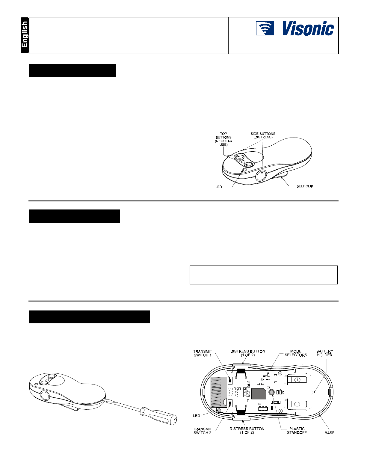
The MCT-124 is a hand-held, 4-button PowerCode UHF transmitter, designed specifically for distress signaling and other tasks
in supervised alarm and remote control systems.
To prevent accidental distress signaling, the two side buttons (one
of which is hidden in Figure 1) have to be pressed simultaneously
to transmit a unique 24-bit PowerCode ID, interpreted as a call for
help. The two buttons at the top can be used to arm/disarm an
alarm system or to activate auxiliary devices. Pressing any one of
the 2 top buttons initiates transmission of a unique 24-bit ID
linked to the specific button, as if it were a separate transmitter.
Each PowerCode ID is factory-selected from 16 million possible
combinations.
A built-in mode selector allows choosing between continuous
transmission for as long as the button is pressed and timed
3-second transmission, no matter how long the button is pressed.
Another built-in mode selector is used to enable/disable a onceper-hour (or according to local standards) supervision message.
Since messages transmitted by the MCT-124 might collide with
other messages sent by other PowerCode transmitters, a smart
anti-collision transmission sequence is used.
Operating power is obtained from an internal long-life 3-volt
lithium battery. An LED lights during transmission, indicating the
battery voltage condition. If the LED flashes during transmission,
the battery must be replaced immediately. In addition, a
transmitter with a weak battery will automatically add a “low
battery” code to each transmission. Compatible receivers are
designed to identify this code and activate a corresponding output.
Each transmitter is supplied with a belt clip that can be optionally
attached to the unit (see Figure 5).
Figure 1. MCT-124, General View
2222. SPECIFICATIONS
. SPECIFICATIONS. SPECIFICATIONS
. SPECIFICATIONS
Frequency (MHz): 315, 433.92, 868.95 or 869.2625 or other
frequencies according to local requirements.
Encoding: 24-bit digital word, over 16 million combinations.
Transmission duration: As long as the button is kept pressed,
or 3-seconds (depending on DIP switch setting).
Power Source: 3V lithium battery, Panasonic CR-2 or
equivalent.
Nominal Battery Capacity: 750 mAh
Battery Supervision: Automatic reporting of battery condition
data as part of any transmission.
Current Consumption: 6 µA standby, 17 mA in operation
(including LED).
Battery Life Expectancy: 3 years (for typical use).
Operating Temperature: 0° to 49°C (32° to 120°F).
Dimensions: 104 x 44 x 24 mm (4-1/8 x 1-3/4 x 15/16 in.).
Weight: 50 g (1-3/4 oz). Color: Dark gray.
Compliance with Standards: Meets FCC Part 15, MPT1340
and and Directive 1999/5/EC
This device complies with the essential requirements and provisions of
Directive 1999/5/EC of the European Parliament and of the Council of
9 March 1999 on radio and telecommunications terminal equipment.
3333. PREPARATION FOR USE
. PREPARATION FOR USE. PREPARATION FOR USE
. PREPARATION FOR USE
3.1 Battery Installation
A. Remove the screw at the back of the unit.
B. Insert a 1/8 inch screwdriver in the slot either at the top or at
the bottom of the case. Rotate the screwdriver handle slightly
until one edge of the cover disengages from the base.
C. Swing up the free end of the cover and separate the cover
from the base.
Figure 2. Opening the Case
D. Extract the transmitter module from the base by grasping the
battery holder and pulling out.
CAUTION! The two rubber membranes at the sides may fall
off. It is advisable to pull them out and put them temporarily
aside, so that they would not get lost.
Figure 3. Component Layout
Page 2
2 DE2415U
E. Insert the 3-volt Lithium battery into the battery holder, so that
the (+) and (–) markings on the battery coincide with the
markings on the printed circuit board (close to each battery clip).
F. Put the printed circuit board (with new battery) back in place.
G. Gently press one pushbutton switch and verify that the LED
lights, indicating good battery condition.
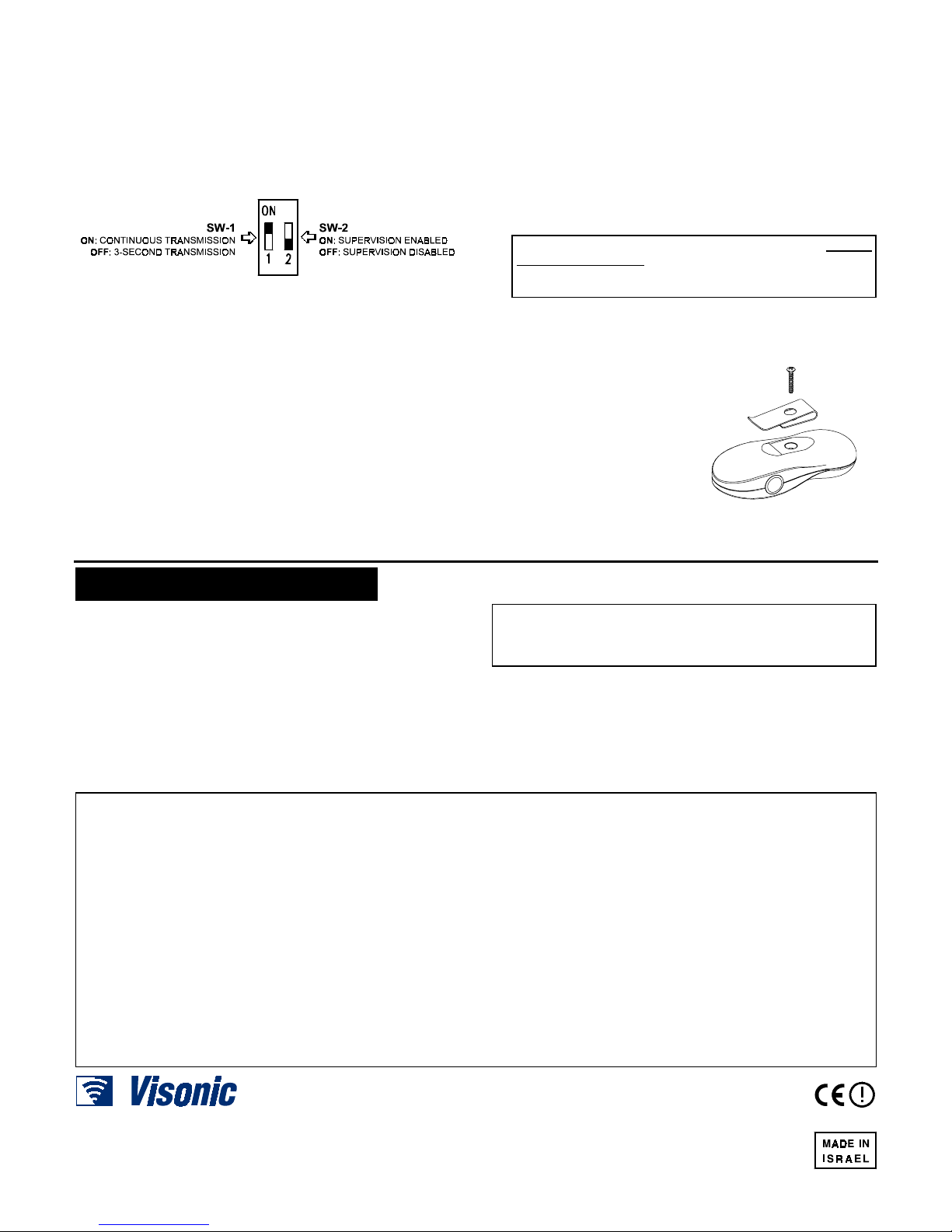
3.2 Setting the Mode Selectors
Two DIP switches on the unit’s printed circuit board allow you to
choose between operating modes, as portrayed in Figure 4.
Figure 4. Mode Switch Tasks and Positions
The factory default settings are as shown in Figure 4. To change
modes, shift the proper switch to the opposite position.
IMPORTANT! Due to a programming delay, wait 4 seconds
before testing a newly selected mode.
3.3 Closing the Case
A. Carefully engage the ridge at the top of the base with the dent
at the top of the cover. Press the bottom ends of both halves
of the case together until they click shut.
B. Push the two rubber membranes in place at the sides of the
case - the concave face should be facing out. Verify that they
are seated well within their respective recesses. Work on one
pushbutton at a time, so as not to trigger a distress signal!
C. Re-insert and tighten the screw at the back of the unit.
Note: If the user needs the belt clip (included), position the
belt clip as shown in Figure 5 and insert the screw through
the hole in the clip.
3.4 Learning and Testing
A . You may test the unit only after having conducted a learning
session at the receiver. Refer to the receiver's installation
instructions, and let the receiver "learn" the ID codes
associated with each pushbutton of the transmitter (the two
side-buttons share the 3
rd
ID).
While the target receiver is in the LEARN mode, a transmission from each pushbutton will enroll its individual ID in the
receiver’s memory.
Since the supervision message is always sent with the first
button's ID, it is mandatory to learn the first button's ID.
Failure to do so will disable the supervision function.
ATTENTION! Because each top pushbutton and the two
side buttons together act as independent transmitters with
individual IDs, make sure that all IDs are learned by the
receiver.
B. Stand 3 m (10 ft) away from the receiver and operate the
transmitter.
C. Verify that the transmitter LED lights, indicating good battery
condition. Also verify that the system responds to your transmission by performing the
desired function.
D. Operate the transmitter
from various locations
within the area covered by
the receiver to determine
"dead" locations, where
transmission is obstructed
by walls and large objects,
or affected by structural
materials.
Figure 5. Belt Clip Installation
4444. NOTES AND WARNINGS
. NOTES AND WARNINGS. NOTES AND WARNINGS
. NOTES AND WARNINGS
Visonic wireless systems are very reliable and are tested to high
standards. However, due to their low transmitting power (required
by regulatory authorities), some limitations must be considered:
A. Receivers may be blocked by radio signals on or near their
operating frequencies, regardless of the code selected.
B. A receiver can only respond to one transmitted signal at a time.
C. Wireless equipment should be tested regularly (at least once
a week) to determine whether there are sources of
interference and to protect against faults.
WARNING: Changes or modifications to this unit not expressly
approved by the party responsible for compliance could void the
user's authority to operate the equipment.
This device complies with FCC Rules Part 15. Operation is
subject to two conditions: (1) This device may not cause harmful
interference, and (2) this device must accept any interference
that may be received or that may cause undesired operation.
Frequency Allocations for Wireless Devices in European
(EU) Countries
• 433.92 MHz has no restriction in any EU member state.
• 315 MHz is not allowed in any EU member state.
• 868.95 MHz (wide band) is allowed in all EU member states.
• 869.2625 MHz (narrow band) is not restricted in any EU
member state.
WARRANTY
WARRANTYWARRANTY
WARRANTY
Visonic Ltd. and/or its subsidiaries and its affiliates ("the Manufacturer") warrants its
products hereinafter referred to as "the Product" or "Products" to be in conformance with
its own plans and specifications and to be free of defects in materials and workmanship
under normal use and service for a period of twelve months from the date of shipment by
the Manufacturer. The Manufacturer's obligations shall be limited within the warranty
period, at its option, to repair or replace the product or any part thereof. The Manufacturer
shall not be responsible for dismantling and/or reinstallation charges. To exercise the
warranty the product must be returned to the Manufacturer freight prepaid and insured.
This warranty does not apply in the following cases: improper installation, misuse,
failure to follow installation and operating instructions, alteration, abuse, accident or
tampering, and repair by anyone other than the Manufacturer.
This warranty is exclusive and expressly in lieu of all other warranties, obligations or
liabilities, whether written, oral, express or implied, including any warranty of
merchantability or fitness for a particular purpose, or otherwise. In no case shall the
Manufacturer be liable to anyone for any consequential or incidental damages for breach
of this warranty or any other warranties whatsoever, as aforesaid.
This warranty shall not be modified, varied or extended, and the Manufacturer does not
authorize any person to act on its behalf in the modification, variation or extension of this
warranty. This warranty shall apply to the Product only. All products, accessories or
attachments of others used in conjunction with the Product, including batteries, shall be
covered solely by their own warranty, if any. The Manufacturer shall not be liable for any
damage or loss whatsoever, whether directly, indirectly, incidentally, consequentially or
otherwise, caused by the malfunction of the Product due to products, accessories, or
attachments of others, including batteries, used in conjunction with the Products.
The Manufacturer does not represent that its Product may not be compromised and/or
circumvented, or that the Product will prevent any death, personal and/or bodily injury
and/or damage to property resulting from burglary, robbery, fire or otherwise, or that the
Product will in all cases provide adequate warning or protection. User understands that a
properly installed and maintained alarm may only reduce the risk of events such as
burglary, robbery, and fire without warning, but it is not insurance or a guarantee that
such will not occur or that there will be no death, personal damage and/or damage to
property as a result.
The Manufacturer shall have no liability for any death, personal and/or bodily injury
and/or damage to property or other loss whether direct, indirect, incidental,
consequential or otherwise, based on a claim that the Product failed to function.
However, if the Manufacturer is held liable, whether directly or indirectly, for any loss or
damage arising under this limited warranty or otherwise, regardless of cause or origin, the
Manufacturer's maximum liability shall not in any case exceed the purchase price of the
Product, which shall be fixed as liquidated damages and not as a penalty, and shall be
the complete and exclusive remedy against the Manufacturer.
Warning: The user should follow the installation and operation instructions and among
other things test the Product and the whole system at least once a week. For various
reasons, including, but not limited to, changes in environmental conditions, electric or
electronic disruptions and tampering, the Product may not perform as expected. The user
is advised to take all necessary precautions for his/her safety and the protection of his/her
property.
6/91
VISONIC LTD. (ISRAEL):
P.O.B 22020 TEL-AVIV 61220 ISRAEL. PHONE: (972-3) 645-6789, FAX: (972-3) 645-6788
VISONIC INC. (U.S.A.):
10 NORTHWOOD DRIVE, BLOOMFIELD CT. 06002-1911. PHONE: (860) 243-0833, (800) 223-0020 FAX: (860) 242-8094
VISONIC LTD. (UK):
FRASER ROAD, PRIORY BUSINESS PARK, BEDFORD MK44 3WH. PHONE: (0870) 7300800 FAX: (0870) 7300801
INTERNET:
www.visonic.com
VISONIC LTD. 2002 MCT-124 (3V) DE2415U (REV. 0, 8/02)
 Loading...