

Page 1
MCT
MCT-100
MCTMCT
-100
-100-100
Supervised Two-Input PowerCode Wireless
Transmitter
1111. INTRODUCTION
. INTRODUCTION
. INTRODUCTION. INTRODUCTION
The MCT-100 is a fully supervised, two-input PowerCode wireless transmitter designed for electronic security applications. Both
inputs can be set to operate with a normally closed (N.C.) loop, or
with an end-of-line (E.O.L.) loop in which both N.C. and N.O.
sensors can be used. An on-board programming DIP switch
allows the installer to disable input No. 1 (IN1) in applications
where only a single input is needed.
Each input has an individual 24-bit PowerCode ID which
identifies it to the target receiver as if it were a separate
transmitter. Each ID is randomly selected in the factory from 16
million possible code combinations.
Disturbing an input loop of the MCT-100 initiates transmission of
the specific input's PowerCode ID followed by various status and
mode designators. Alarm information and other data are thus
forwarded to the alarm control panel or to the head-end
computer, depending on the type of system in which the
MCT-100 is used.
Since messages transmitted by the MCT-100 might collide with
messages sent by other PowerCode transmitters, a "smart"
anti-collision transmission sequence is used (see Appendix A).
The MCT-100 is protected by a tamper switch, activated when
the cover is removed. Once the tamper switch contacts open, a
message will be transmitted from input 1 with the “tamper alert”
marker ON. If the installer disables input 1, the tamper situation
will be automatically reported by input 2 instead.
A periodic supervision message, distinguished by a specific
marker, is transmitted automatically from input 1 only (if enabled)
or from input 2 only (if input 1 is disabled). The supervision
message is transmitted once per 15 minutes by all models,
except for the 315 MHz model which sends this message once
per 60 minutes. The receiver is thus informed, at regular
intervals, of the MCT-100 active participation in the system.
An indicator LED lights during transmission whenever alarm or
tamper events are reported. The LED does not light while a
supervision message is being transmitted.
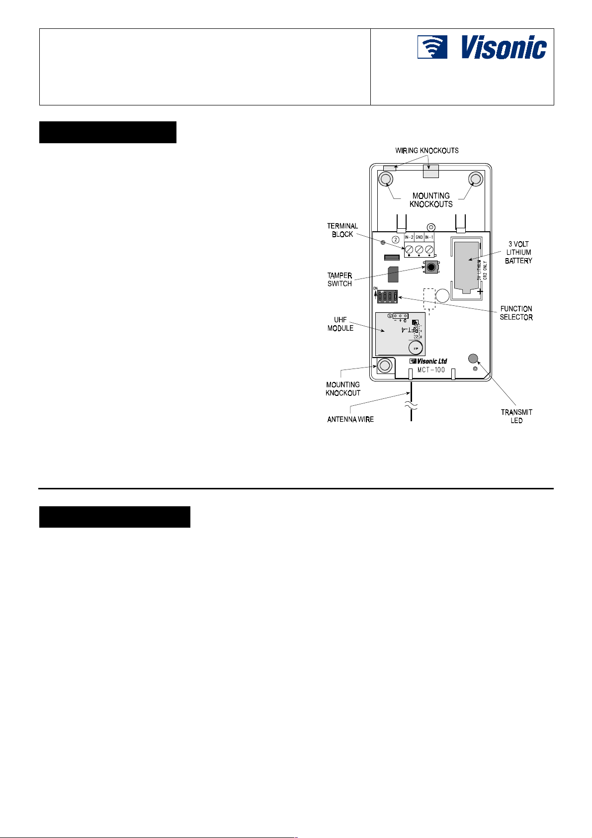
Installation Instructions
Figure 1. MCT-100, Cover Removed
Operating power is obtained from an on-board 3 V Lithium
Thionyl-Chloride battery. A weak battery will cause a "low battery"
designator to be added to any message transmitted (see Appendix
A for details).
2222. SPECIFICATIONS
. SPECIFICATIONS
. SPECIFICATIONS. SPECIFICATIONS
) battery,
Frequency (MHz): 315, 433.92, 868.95 and 869.2625 or other
frequencies according to local requirements
Transmitter's ID Code: 24-bit digital word, over 16 million
combinations, pulse width modulation.
Overall Message Length: 36 bits
Alarm Inputs: 2, each with a separate 24-bit transmitter ID
Input Circuit Type: N.C. / E.O.L., selected with on-board DIP
switch
E.O.L. Resistor Required: 47 kΩ
Message Repetition: Repetitive transmission (once every 3
minutes) or one-shot, as selected with on-board DIP switch.
Supervision: Signaling at 15-minute intervals (60 minute
intervals for the 315 MHz model) from input 1 if enabled, or from
input 2 if input 1 is disabled.
Response to Tamper Event: Tamper report every 3 minutes
(until the tamper switch is restored).
DE2241U 1
Power Source: 3 V Lithium Thionyl Chloride (LiSOCl
Panasonic CR-2.
Nominal Battery Capacity: 750 mAh
Current Consumption: 6 µA standby, 17 mA average in
operation (including LED)
Battery Life (with LED on):
@ 10 transmissions per day: About 50 months
@ 50 transmissions per day: About 45 months
Battery Supervision: Automatic transmission of battery
condition data as part of any status report.
Operating Temperature: 0°C to 49°C (32°F to 120°F).
Dimensions: 110 x 63 x 25 mm (4-5/16 x 2-1/2 x 1 in.).
Weight: 66.5 g (2.34 oz)
Compliance with Standards: Meets FCC Part 15, MPT1349 and
Directive 1999/5/EC
2
Page 2
3333. INSTALLATION
. INSTALLATION
. INSTALLATION. INSTALLATION
3.1 Mounting
Remove the screw from the front
cover (Fig. 2) and separate the front
cover from the base.
The plastic cap shown is supplied
separately in a small nylon bag keep it for later use. Mount the base
equipped with the printed circuit
Figure 2. Cover Assembly
board in the selected location, using the mounting and wiring
knockouts shown in Fig. 1.
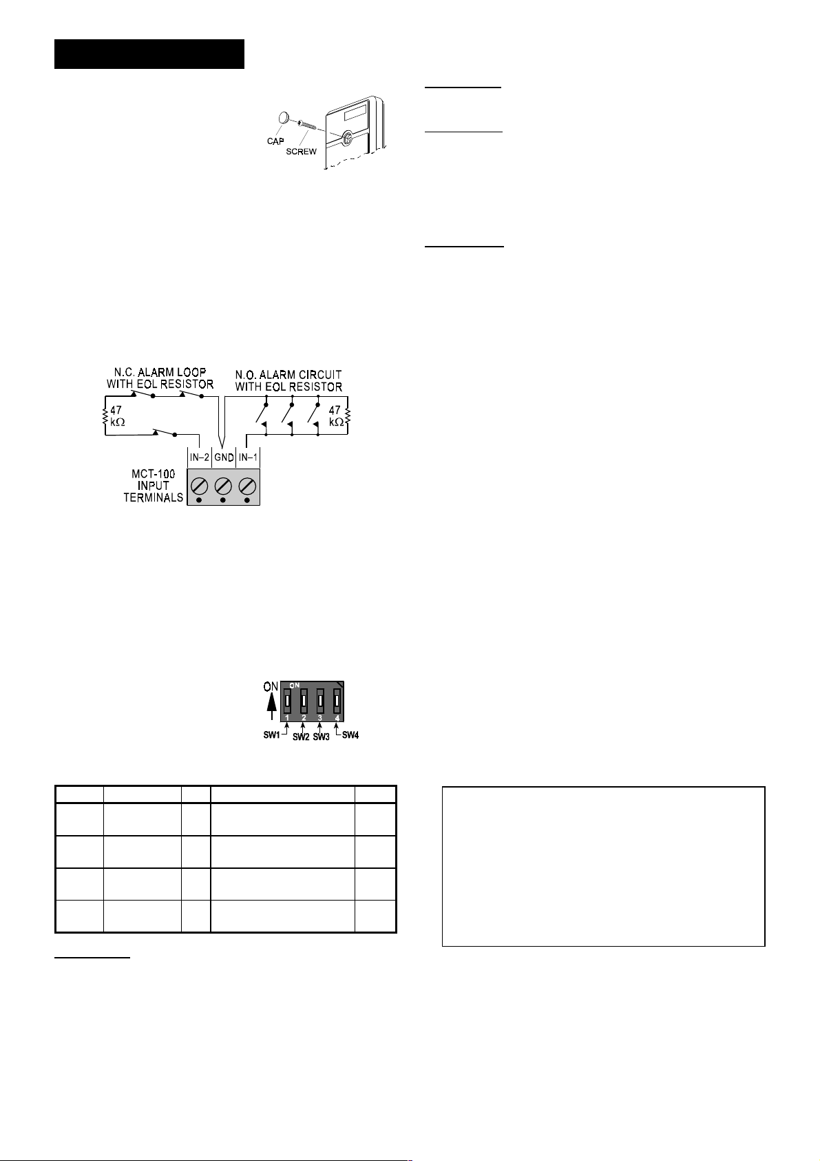
3.2 Wiring
Route the wires through a wiring knockout in the base.
If an input is defined as a Normally Closed (N.C.) type (SW-1 or
SW-2 are set to OFF), series connected normally closed sensor
contacts must be used exclusively.
If an input is defined as an E.O.L. type, Normally Closed (N.C.)
as well as Normally Open (N.O.) sensor contacts can be used. A
47 kΩ resistor must be wired at the far end of the E.O.L. zone
loop, as in Figure 3.
Figure 3. Wiring Example with E.O.L Resistors
Notes:
1. An alarm message will be transmitted once the loop is opened
or short circuited.
2. If you do not need input No. 2, connect it to the GND terminal
with a short length of jumper wire (in case of N.C.) or with a
47 k
resistor (in case of E.O.L.).
Ω
3.3 Setting the Function Selector
Before testing, set DIP switches SW1 through SW4 as required
for the particular application.
The MCT-100 is equipped with
a 4-position DIP switch function
selector (Fig. 4). Each switch
lever allows you to select one
of two options, as explained in
the following table:
Table 1. Getting acquainted with the function selector
Switch Function Pos. Selected Option Default
SW1
SW2
SW3
SW4
IN1 enable/
disable
EOL for IN1
and IN2
Restore reports
enable/disable
Transmit mode
selector
ON
OFF
ON
OFF
ON
OFF
ON
OFF
SWITCH SW1: Determines whether input 1 (IN1) will be enabled
or disabled.
Figure 4. Function Selector
Input No. 1 is enabled
Input No. 1 is disabled
Inputs are E.O.L. (47 kΩ)
Inputs are N.C.
Restore events reported
Restore events not reported
Alarms reported every 3 min.
Alarms reported only once
ON
OFF
ON
OFF
SWITCH SW2: Determines whether both inputs will behave as
47 kΩ end-of-line (E.O.L.) circuits or as normally closed (N.C.)
inputs.
SWITCH SW3: Determines whether the transmitter will report
“restore” events.
Note: If the MCT-100 is used in conjunction with motion
detectors, there is no point in setting SW3 to ON, because the
detector restores automatically after an alarm. However, when
the MCT-100 is used with a door or window magnetic switch,
selecting the ON position will enable you to find out whether the
door or window under surveillance are open or closed.
SWITCH SW4: In non-supervised systems, it is sometimes
required to report an alarm repeatedly at short intervals, until the
disturbed input reverts to its normal (undisturbed) state. Switch
SW4 is used to select between repetitive and one-shot
transmission.
Note: Transmissions initiated by "tamper” events will be repeated
once every 3 minutes, regardless of SW4 setting.
3.4 Battery Insertion and Test
A . Insert the 1/2 AA battery between the battery clips, making
sure that the polarity is correct. For proper operation, only
Lithium Thionyl Chloride battery (as specified in Section
2) should be used.
Note: Before each supervision report, the battery voltage is
tested. If a low battery condition is detected, a "low battery"
alert signal will be included in the supervision message.
If the battery is not replaced, all following transmissions will
include the "low battery" alert signal, which has to be acted
upon without delay.
B. Since the cover is removed and power is applied, a tamper
situation exists. Verify that the MCT-100 transmits (the LED
lights briefly) once every 3 minutes.
C. When you are satisfied that tamper transmissions are carried
out properly, put the cover back on to return the tamper switch
to its normal undisturbed position. W ait slightly over 3 minutes
to verify that tamper transmissions cease.
D. Momentarily disturb any one of the sensors connected to the
first input (IN1) and verify that the transmitter LED lights,
indicating that transmission is in progress. IF SW4 is on, wait
3 minutes to verify that the transmission is repeated at
3-minute intervals.
E. Restore the sensor to the undisturbed state and watch the
LED. If SW3 is set to ON, another transmission will take place
upon restoral.
F. Repeat Steps D and E above with the second input (IN2).
G. Refer to the target receiver's installation instructions, and let
the receiver "learn" the ID codes associated with both inputs
of the MCT-100.
ATTENTION! Because each input of the MCT-100 acts as
an independent transmitter with an individual ID, make sure
that both input IDs are learned by the receiver.
With the target receiver in the LEARN mode, an alarm
transmission from each input will enroll the input’s ID in the
receiver’s memory.
A tamper transmission will also work if you remember this:
- If the Input No. 1 is enabled (SW1 is ON), the tamper
message will be sent with Input 1’s ID.
- If Input No. 1 is disabled (SW1 is OFF), the tamper
message will be sent with Input 2’s ID.
H. Secure the front cover with the screw and screw cap (Fig. 2).
2 DE2241U
Page 3
4444. MISCELLANEOUS COMMENTS
. MISCELLANEOUS COMMENTS
. MISCELLANEOUS COMMENTS. MISCELLANEOUS COMMENTS
4.1 Product Limitations
Visonic Ltd. wireless systems are very reliable and are tested to
high standards. However, due to low transmitting power and
limited range (required by FCC and other regulating authorities),
there are some limitations to be considered:
A. Receivers may be blocked by radio signals occurring on or near
their operating frequencies, regardless of the digital code used.
B. A receiver can only respond to one transmitted signal at a time.
C. Wireless equipment should be tested regularly to determine
whether there are sources of interference and to protect
against faults.
4.2 Statements
This device complies with Part 15 of the FCC Rules and
RSS-210 of Industry and Science Canada. Operation is subject
to the following two conditions: (1) This device may not cause
harmful interference, and (2) this device must accept any
interference received, including interference that may cause
undesired operation.
APPENDIX A. THE VISONIC LTD. POWERCODE SYSTEM
APPENDIX A. THE VISONIC LTD. POWERCODE SYSTEM
APPENDIX A. THE VISONIC LTD. POWERCODE SYSTEMAPPENDIX A. THE VISONIC LTD. POWERCODE SYSTEM
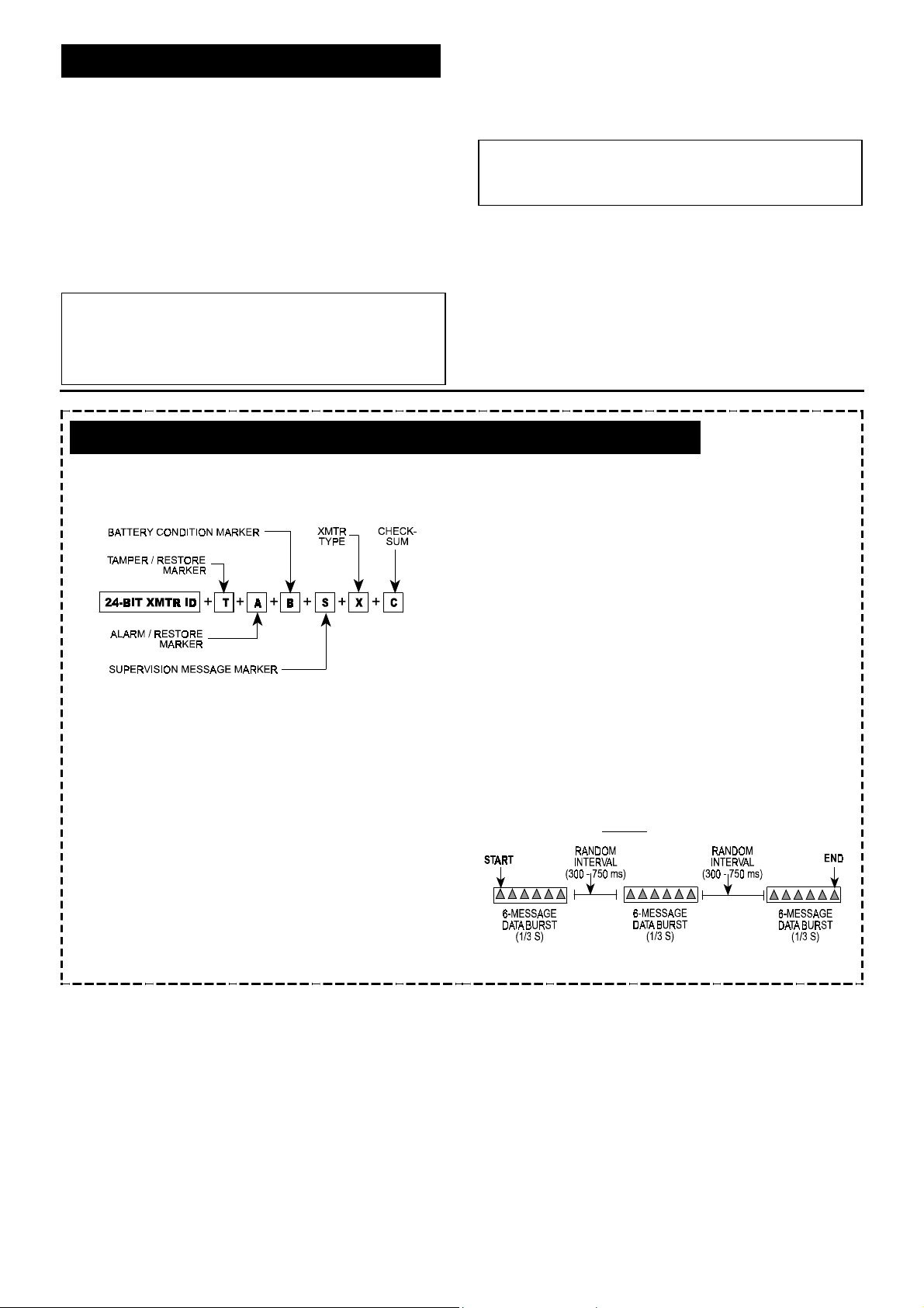
A-1. The PowerCode Message Format
The PowerCode message transmitted by the MCT-100 includes
the 24-bit ID of the input of origin and a status report (see Fig. A1).
Figure A1. Transmitted Data
A message includes the following data:
• Input ID: The 24-bit ID of the input sending the message.
• Tamper / Restore: Upon removal of the unit's front cover,
Input 1 (or input 2 if input 1 is disabled) will send out a
message with a "tamper marker" set to ON. If the unit's cover
is put back, the “input in charge of reporting” will initiate a
message with the tamper marker OFF ("Tamper Restore").
• Alarm / Restore: Once the input loop is disturbed, a message
will be transmitted with an "Alarm marker" ON. Upon restoral
of the input loop, a message will be transmitted with the alarm
marker set to OFF (provided that restore transmission is
desired - SW-3 has been set to ON - see Para. 3.3.).
Low Battery: A special battery condition marker is used to
report the battery status in any message. The battery is tested
once an hour and if found low, Input 1 will initiate a message
in which the "Low Battery” marker is set to ON. This marker
will be ON in all messages that follow, whatever the cause
for transmission. Once the battery is restored to normal,
this
The user is cautioned that changes or modifications to the
unit, not expressly approved by Visonic Ltd., could void the
user's FCC or other authority to operate the equipment.
This device complies with the essential requirements and
provisions of Directive 1999/5/EC of the European Parliament and
of the Council of 9 March 1999 on radio and telecommunications
terminal equipment.
4.3 Frequency Allocations for Wireless
Devices in European (EU) Countries
• 433.92 MHz has no restriction in any EU member state.
• 418 MHz is allowed in the UK only.
• 315 MHz is not allowed in any EU member state
• 868.95 MHz (wide band) is allowed in all EU member states
except for Belgium.
• 869.025 MHz and 869.2625 MHz (narrow band) are not
restricted in any EU member state.
marker will be OFF in all messages that follow (“Battery
Restore”).
• Supervision Report: A special "supervision message”
marker, when set to ON, identifies the periodic supervision
messages transmitted automatically at 60 minute intervals.
This marker will be OFF in all other messages. Supervision
messages are sent by input 1 (if enabled) or by input 2 (if
input 1 is disabled).
• Transmitter Type: A special marker indicates the type of the
transmitter:
Supervised or non-supervised
"
Reports or does not report restorals after alarm
"
• Checksum: Checksum bits at the end of the message allow
the receiver to determine whether an incoming message is
valid (error-free). This feature considerably upgrades the
reliability of the wireless communication link.
A-2. Anti-Collision
To overcome message collisions at the receiving end, Power-
Code transmitters transmit 3 data bursts at random intervals,
with 6 repetitions of the same message in each burst (Fig. A2).
This redundancy improves the probability of reception.
Note: Periodic supervision messages are an exception to this
rule - they consist of a single 6-message burst.
Figure A2. Anti-Collision Transmission Sequence
DE2241U 3
Page 4

WARRANTY
WARRANTY
WARRANTYWARRANTY
Visonic Ltd. and/or its subsidiaries and its affiliates ("the Manufacturer") warrants its
products hereinafter referred to as "the Product" or "Products" to be in conformance with
its own plans and specifications and to be free of defects in materials and workmanship
under normal use and service for a period of twelve months from the date of shipment by
the Manufacturer. The Manufacturer's obligations shall be limited within the warranty
period, at its option, to repair or replace the product or any part thereof. The Manufacturer
shall not be responsible for dismantling and/or reinstallation charges. To exercise the
warranty the product must be returned to the Manufacturer freight prepaid and insured.
This warranty does not apply in the following cases: improper installation, misuse,
failure to follow installation and operating instructions, alteration, abuse, accident or
tampering, and repair by anyone other than the Manufacturer.
This warranty is exclusive and expressly in lieu of all other warranties, obligations or
liabilities, whether written, oral, express or implied, including any warranty of
merchantability or fitness for a particular purpose, or otherwise. In no case shall the
Manufacturer be liable to anyone for any consequential or incidental damages for breach
of this warranty or any other warranties whatsoever, as aforesaid.
This warranty shall not be modified, varied or extended, and the Manufacturer does not
authorize any person to act on its behalf in the modification, variation or extension of this
warranty. This warranty shall apply to the Product only. All products, accessories or
attachments of others used in conjunction with the Product, including batteries, shall be
covered solely by their own warranty, if any. The Manufacturer shall not be liable for any
damage or loss whatsoever, whether directly, indirectly, incidentally, consequentially or
otherwise, caused by the malfunction of the Product due to products, accessories, or
attachments of others, including batteries, used in conjunction with the Products.
The Manufacturer does not represent that its Product may not be compromised and/or
circumvented, or that the Product will prevent any death, personal and/or bodily injury
and/or damage to property resulting from burglary, robbery, fire or otherwise, or that the
Product will in all cases provide adequate warning or protection. User understands that a
properly installed and maintained alarm may only reduce the risk of events such as
burglary, robbery, and fire without warning, but it is not insurance or a guarantee that such
will not occur or that there will be no death, personal damage and/or damage to property
as a result.
The Manufacturer shall have no liability for any death, personal and/or bodily injury
and/or damage to property or other loss whether direct, indirect, incidental,
consequential or otherwise, based on a claim that the Product failed to function.
However, if the Manufacturer is held liable, whether directly or indirectly, for any loss or
damage arising under this limited warranty or otherwise, regardless of cause or origin, the
Manufacturer's maximum liability shall not in any case exceed the purchase price of the
Product, which shall be fixed as liquidated damages and not as a penalty, and shall be the
complete and exclusive remedy against the Manufacturer.
Warning: The user should follow the installation and operation instructions and among
other things test the Product and the whole system at least once a week. For various
reasons, including, but not limited to, changes in environmental conditions, electric or
electronic disruptions and tampering, the Product may not perform as expected. The user
is advised to take all necessary precautions for his/her safety and the protection of his/her
property.
6/91
VISONIC LTD. (ISRAEL): P.O.B 22020 TEL-AVIV 61220 ISRAEL. PHONE: (972-3) 645-6789, FAX: (972-3) 645-6788
VISONIC INC. (U.S.A.): 10 NORTHWOOD DRIVE, BLOOMFIELD CT. 06002-1911. PHONE: (860) 243-0833, (800) 223-0020. FAX: (860) 242-8094
VISONIC LTD. (UK): FRASER ROAD, PRIORY BUSINESS PARK, BEDFORD MK44 3WH. PHONE: ( 0870) 7300800 FAX: (0870) 7300801
INTERNET:
VISONIC LTD. 2002 MCT-100 DE2241U- (REV. 0, 3/02)
4 DE2241U
www.visonic.com
 Loading...