

Page 1
D-304915 1
MCS
MCSMCS
MCS----740
740740
740
Fully Wireless Outdoor Siren
Installation Instructions
1. INTRODUCTION
1. INTRODUCTION1. INTRODUCTION
1. INTRODUCTION
The MCS-740 is a fully wireless outdoor siren, designed for installation
in areas in which wiring action is difficult or impossible. It is compatible
with control panels such as PowerMax Pro, PowerMaxComplete,
PowerMaxExpress or Visonic newer panels (not compatible with
PowerMax+ and PowerMax control panel).
Features
• Siren and strobe light activation: The siren produces a strong
alarm noise and emits flashing light to deter intruders and guide
police to the site.
Notes:
The duration of the siren's alarm is controlled from the control panel
by setting the "Bell Time" option (refer to alarm system installer
guide, par. 4.4) and should be set according to local authorities
requirements.
The strobe light operates (every 1 second) for 20 minutes after
siren stops or until the system is disarmed, whichever occurs first.
• 2 Types of alarm indication
The siren produces different alarm signals for Burglar and Fire.
• Squawk indication: Squawk (beep) sounds can be used to
indicate alarm system arming (1 squawk) and disarming (2
squawks) by a keyfob (squawk can be enabled from the control
panel User menu).
• Tamper / supervision failure indication: Siren is equipped with
tamper protection, which produces alarm if a burglar attempt to
open the siren's cover or remove siren from wall.
• Low battery voltage alert
The siren reports a low battery message to the alarm system when
battery is about to drain. After low voltage is reported, at least 2
siren alarms are possible before the siren is totally inactive.
• Strobe Light Color: The siren can be purchased with red, blue,
amber or transparent lens, according to the desired strobe light color.
• Siren activity LED: A flashing LED (optional, at the bottom of the
siren front panel) indicates siren activity (can be disabled by an
internal jumper, see fig. 3, step 8)
• 2-way full supervision
The siren is fully supervised, 2-way communication device. It
periodically transmits its status signal to the alarm system.
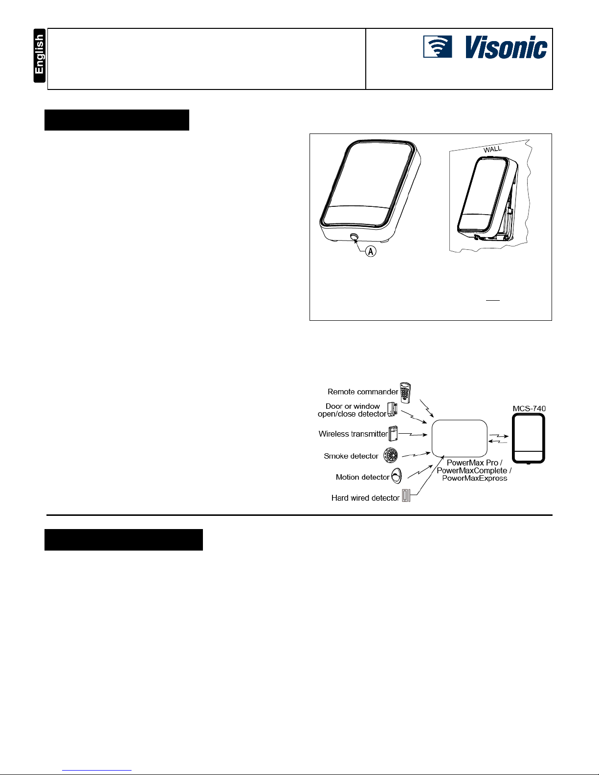
Fig. 1a
- External View
Fig. 1b – Mounting Position
A. MCS-740 can be recognized outwardly by its red screw cap.
IMPORTANT! The MCS-740 siren must be installed on the wall in a
vertical position with the screw pointing to the floor only, as illustrated
in Figure 1b. The importance of correct positioning of the MCS-740 is
to enable the siren to function as a waterproof device.
• Installation diagnostics
The transmitted signal strength can be measured during the
installation (refer to the alarm system Installer guide, par. 5.2 –
Diagnostic Test).
• Self-test function
Upon pressing the self test switch, siren functional check is performed low level sounds and flash light indicate that the siren is serviceable.
Figure 2- Typical Integration with the Alarm System
2. SPECIFICATIONS
2. SPECIFICATIONS2. SPECIFICATIONS
2. SPECIFICATIONS
Siren Type: One Piezo 109 db. Sound Pressure Level @ 1m, 1.8-3.5
kHz, sweep frequency 7 Hz. Additional piezo is optional.
Battery: Four 3.6V/3.5A/H Lithium independent cells (EVE
ER18505M) assembled in two plastic wrappings and connected to the
cable adaptor (see Figure 3). Visonic assembly catalog no. 103-
304742.
Caution! Risk of explosion if battery is replaced by an incorrect type.
Dispose of used battery according to the manufacturer's instructions.
Battery Life Time: 3 years (taking into consideration a typical alarm
of 4 minutes Piezo + strobe operation per week).
Current Consumption: Standby - 250µA average, Operation - 300mA
average.
Compliance with Standards: EN 50131-1 Grade 2 Class 4,
EN50131-4, EN301489, EN50130-4, EN50130-5, ETSI EN 300 220,
IP55,
Operating Frequency (MHz): 433.92, 868.95
Supervision Time: 5 minutes
Strobe Light: Pulsed @ 1 sec.
Dimensions (LxWxD): 295x186x63mm (11-5/8 x 7-5/16 x 2-1/2 in)
Color: White (with red, blue, amber or transparent lens)
Operating Temperature: -33°C to 70°C (-27.4°F to 158°F), RH
humidity 75%.
Weight (including battery): 970g (34 oz)
Note: The manufacturer is not responsible for any radio or TV
interference caused by unauthorized modifications to this equipment.
Such modifications could void the user's authority to operate the
equipment.
Page 2
2 D-304915
3. INSTALLATION
3. INSTALLATION3. INSTALLATION
3. INSTALLATION, TESTING AND ENROLLING
, TESTING AND ENROLLING, TESTING AND ENROLLING
, TESTING AND ENROLLING
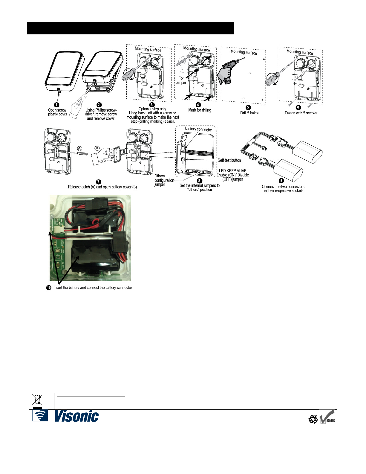
3.1 Installation
Figure 3 – Installation
3.2 Self-Test
Press the self test button (see figure 3 step 8). Low level piezo
sounds and flash lights indicate that the siren is fully operational.
3.3 Configuration (see figure 3, step 8)
LED Keep Alive Jumper Setup:
When it is desired that the Keep Alive LED should blink (every 5
sec.); LED configuration must be set to ON position.
PowerMax+ / Other Jumper Setup
The internal jumper must be set to “others” position.
3.4 Enrolling
Important Note: The siren is ready to operate 30 seconds after the
enrolling. Pre-enrolled sirens are ready to operate 30 seconds after
power up.
The alarm system must recognize the siren's unique identification code
for command delivery and supervision. To enroll the siren into the alarm
system memory, refer to the ENROLLING section of the alarm system
installation instructions, and momentarily press the Self-Test button (see
figure 3 step 8) when you are instructed.
After the enrolling, close the siren's cover and perform diagnostic test,
as described in the alarm system installer guide, DIAGNOSTIC
section.
Enrolling cancellation, if required, is also described in the alarm
system Installer Guide, ENROLLING section.
W.E.E.E. Product Recycling Declaration
For information regarding the recycling of this product you must contact the company from which you orignially purchased it. If you are discarding this product and not
returning it for repair then you must ensure that it is returned as identified by your supplier. This product is not to be thrown away with everyday waste.
Directive 2002/96/EC Waste Electrical and Electronic Equipment.
EMAIL: info@visonic.com
INTERNET: www.visonic.com
VISONIC LTD. 2013 MCS-740, D-304915 (Rev 0, 10/13) Refer to separate W arranty statement Based on D-301680 Rev 4
 Loading...