

Page 1
MC-312 PG2
Outdoor PowerG wireless magnetic contact with auxiliary input
1. INTRODUCTION
The MC- 312 PG2 isa two-way wirelessPowerG magnetic contact device
that is compatible with PowerMaster control panels.
The device has the following features:
l Weatherproof, water-resistant outdoor transceiver
l Functions in extreme temperature (-40 °C to 66 °C / -40 °F to 151
°F) and is IP66 certified.
l Battery life of up to 5 years (with typicaluse)
l Integrated magnetic sensor
l Anti-masking protection, based on panel software version.
l Auxiliary hard-wired input, programmable as either NO, NC, EOL or
DEOL (based on panel version support) for use with additional
devices
l Maximum magnet gap of 44.5 mm (1¾ in) on wood and 31.8 mm
(1¼ in) in on metal.
l Ability to disable the magnetic sensor if the auxiliary input only is
required
l The sensor and the auxiliary input can behave as separate
transmitters, although they trigger the same RF transmitter.
l Front and backtamper protection (back tamper not available in US
market)
l Automatic periodic supervision at regular intervals
l PowerG two- way Frequency Hopping Spread Spectrum FHSS-
TDMA technology
Installation Instructions
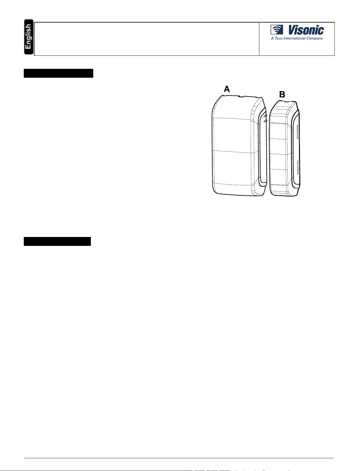
Figure 1- MC-312 PG2
A: Device B:Magnet
2. INSTALLATION
The equipment is designed to be installed only by qualified service persons.
It isrecommended to place the transmitter above the door or window on the fixed frame and the magnet to the movable part of the door or window.
Make sure that the magnet is located not more than 44 mm (1.75 in) from the marked side of the transmitter.
It isalso possible to mount the MC-312 PG2 on a curved surface, such as a fence pole or similar, to monitor outdoor areas.
In case of roller shutter assembly, the magnet needs to be assembled25mm – 35mm from the sensor.
Note: Once the battery cover isremoved, a tamper message is tr ansmitted to the panel. Subsequent removal of the battery prevents transmission of
the TAMPER RESTORE alert, leaving the receiver in permanent alert. To avoid this, press the tamper switch when you remove the battery.
Caut ion! Riskof explosion if the battery isreplaced by an incorrect type. Dispose of the used battery according to the manufacturer’s instructions.
Attent ion ! The unit has an optional back tamper switch behind the device. As long as the device isseated firmly within the bracket, the switchlever will
be pressed against a specialbreak-away bracket segment that islooselyconnected to the bracket. Be sure to fasten the break-away segment to the
wall. If the detector unit is forciblyremoved from the wall, this segment willbreak away from the bracket, causing the tamper switch to open.
2.1. Mounting the MC-312 PG2 on a flat surface
To mount the device on a flat surface, complete the following steps:
1. Insert a flat-head screwdriver into the slot provided and push upward to remove the decorative cover, as in Fig. 2.
2. Unscrew the lower screw from the device cover, as in Fig. 3.
3. Separate the device from the bracket, as in Fig. 4.
4. Mark and drillfour holes in the mounting surface, as in Fig. 5.
5. Screw in the bracket with four screws provided.
6. Reattach the device to the bracket.
7. Mount the magnet base with two supplied screws to an adjacent surface and attach the magnet to the magnet bracket, as in Fig. 5.
Note: Align the device and magnet according to the specifications in "Range coverage directions" on the next page.
D-307174 MC-312 PG2 Installation Instructions 1
Page 2
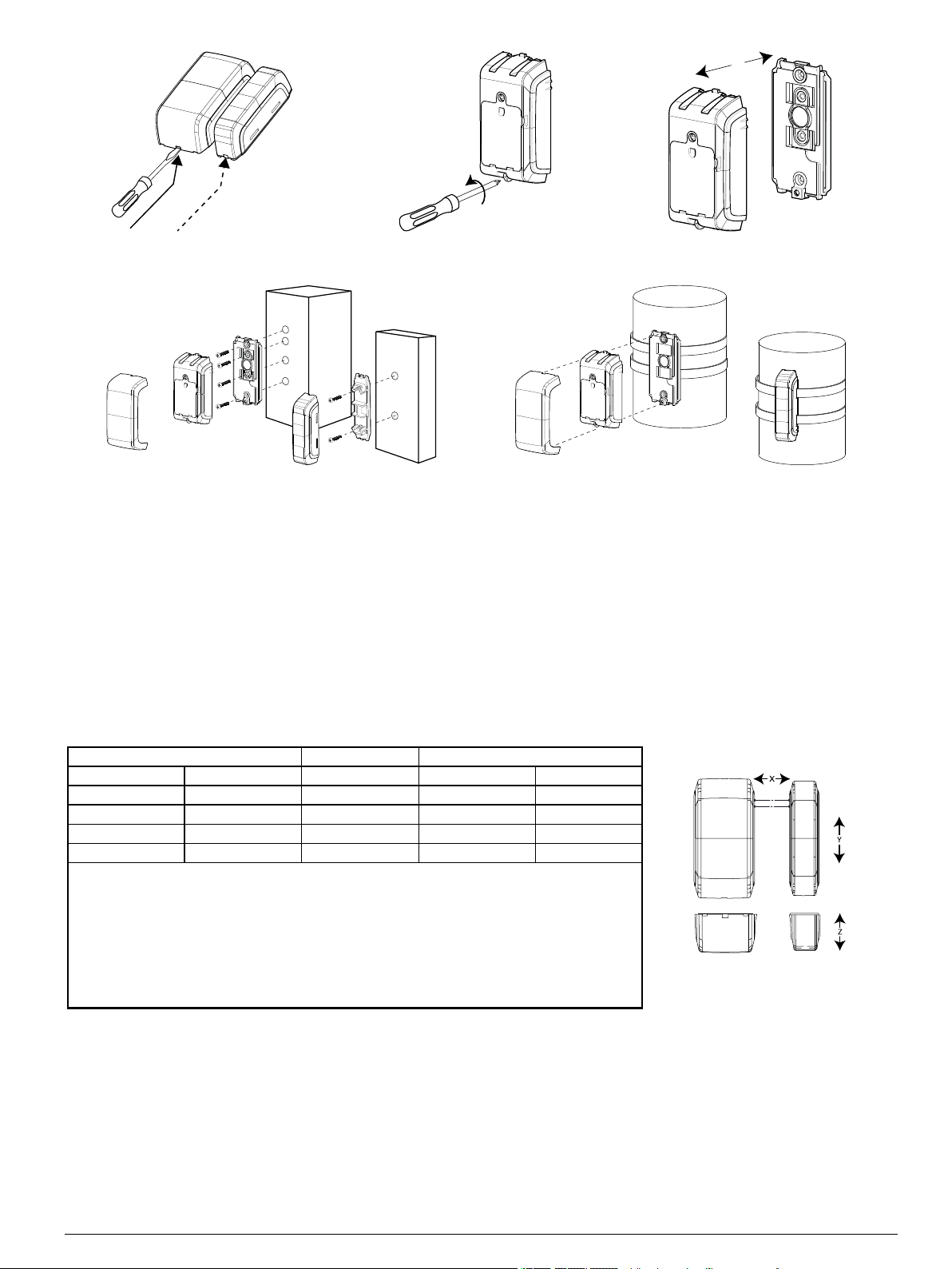
Figure 2 - Decorative cover removal Figure 3 - Unscrewing device Figure 4 - Device and bracket separation
Figure 5 - F lat surface mounting Figure 6 - Curved surface mounting
2.2. Mounting the MC-312 PG2 on a curved surface
1. Insert a flat-head screwdriver into the slot provided and push upward to remove the decorative cover, as in Fig. 2.
2. Unscrew the lower screw from the device cover, as in Fig. 3.
3. Separate the device from the bracket, as in Fig. 4.
4. Feed both straps through the slots provided in the bracket, as in Fig. 6.
5. Fasten both straps to the desired curved surface and position the connecting sections of the straps at the location of the bracket.
6. Separate the magnet bracket and cover and feed both straps through the slots provided on the cover.
7. Close the magnet and fasten both straps to the desired curved surface and position the connecting sectionsof the straps at the location of the
bracket.
Note: Align the device and magnet according to the specifications in "Range coverage directions" below.
2.3. Range coverage directions
Non -metallic surface Supp orts Metallic surface
Open Close Direction Open Close
71 mm 52 mm X 48 mm 35 mm
40 mm 33 mm Y (up) 32 mm 25 mm
22 mm 17 mm Y (down) 17 mm 8 mm
85 mm 55 mm Z 55 mm 30 mm
Table 1 - Ran ge co verage d irections
Note: Values stated above may vary by up to 10%. F or steel installations, the gaps cannot be lessthan
3.2 mm.
Note: In case of roller shutter assembly, the magnet needs to be mounted 25 mm - 35 mm (on the X
plane) from the device. F or all other installations, a minimum gap of 5 mm is needed.
Tip: When mounting on a slide door, refer to X. When mounting on a roller shutter, refer to Y. When
mounting on a normal door, refer to Z.
Figure 7 - Range coverage directions
D-307174 MC-312 PG2 Installation Instructions 2
Page 3
2.4. Enrolling the MC-312 PG2
Refer to the relevant control panel installer guide and follow the procedure under the “02: ZONES/DEVICES” option of the Installer Menu. A general
description of the procedure is provided in the following flow chart.
Step 1 Step 2 Step 3 Step 4 Step 5 Step 6
Enter the installer
menu and select 02:
ZONES / DEVICES
02:ZONES DEVICES > ADD NEW DEVICES > Z06: LOCATION
Notes:
If the magnetic contact deviceis already enr olled you can configure the magnetic contact device
parameters using the Modify Devicesoption (see step 2).
Select the Device Settings option and refer to "Configuring the MC-312 PG2device parameters" below to
configure the device parameters.
To enroll the device as noted in step 3, you can power on the device, press the enrollment button, or
remove the pull tab on new devices ( see Fig. 8).
Select ADD NEW
DEVICE. See note [1]
Enroll the device or
enter the device ID
ENROLL NOW or
ENTER
ID: XXX-XXXX >
Select the desired
zone number
Z06: Co ntact
Sensor ID No .
107-XXXX
Configure the
location, zone type,
and chime
parameters
Z06: ZONE T YPE
Z06: SET CHIME
Z06: DEV
SETTINGS
Seesection 2.7
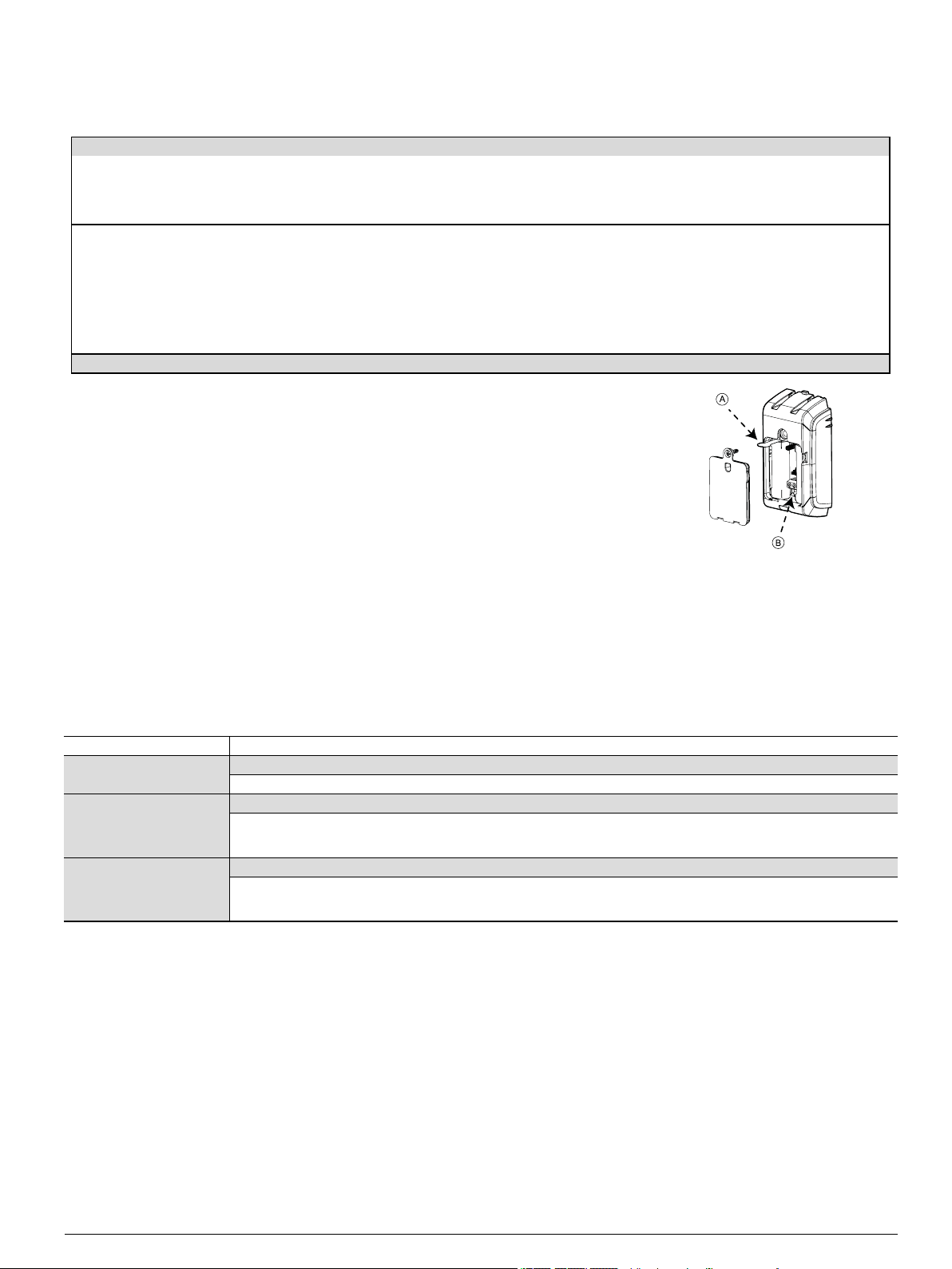
Figure 8 - Enrollment options
Configure the
detector
A: Enrollment tab
B: Enrollment button
2.5. Configuring the MC-312 PG2device parameters
Enter the control panel DEVICE SETTINGS menu and follow the configuration instructions for the MC-312 PG2 magnetic contact device as described
in the Table 2.
Option Con fig uration in structio ns
Magnetic sensor Determine whether to enable or disable the magnetic sensor.
Optional settings: Enabled (default) or Disabled.
Input #1 Define the external input according to the installer's requirements.
Optional settings: Disabled (default), No rmally Open, Normally Closed, End of L ine, or Double End of Line.
Note: DEOL support is dependent on panel software version.
Anti-mask Determine whether to enable or disable the anti-masking protection.
Optional settings: Enabled or Disabled (default).
Note: Thisfeature isdependent on panel softwar e version.
Table 2 - Magnetic device parameters
D-307174 MC-312 PG2 Installation Instructions 3
Page 4

2.6. Wiring the auxiliary input
Notes:
For UL installations, the device connected to the initiating circuit must be
located in the same room as the transmitter.
For UL installations, connect to UL listed residential burglar alarm
accessories only.
For ULC installations, connect ULC listed products onlyto the auxiliary
wiring input.
An alarm message is transmitted once the loop is opened or short
circuited.
To connect thisdevice with another nearby device viaauxiliary input,
complete the following steps:
1. Remove the jacket at the end of the cable to expose the wires within.
2. Perforate the silicon gasket, at the back of the device, with a 0.8 mm
(1/32 in) pin.
3. Pass each wire through an entry hole and out the opposite side.
4. Remove the insulation from the end of each wire.
5. Connect each wire to the r elevant terminal, referencing"Auxiliary
wiring options" below.
6. Screw the ter minal closed using a flat head screwdriver.
Notes:
Use a 22 AWG AUX cable for thisinstallation.
Use a cableshorter than 3 m (10 ft) for the AUX connection.
Seal the auxiliary wiring gasket with RTV Silicone adhesive sealant.
Figure 9- Auxiliary wiring
2.7. Auxiliary wiring options
You can add mor e devicesto the circuitof the MC-312 PG2 for normally closed, normally open or end of line applications. Each application type is
explained in the table below:
Normallyclosed (NC) Exclusively use series connected NC sensor contacts if the auxiliary input of the MC-312 PG2 is defined as a normally
closed (NC) type. An EOL resistor is not required.
Normallyopen (NO) Exclusively use parallel connected NO sensor contactsif the auxiliary input of the MC-312 PG2 isdefined as NO type.
An EOL resistor is not required.
End of Line (EOL) For EOL supervision, NC sensor contacts can be used. A 5.6 kΩ EOL resistor may be wired at the far end of the zone
loop.
Note: Figure 10 illustrates a DEOL (Double End of Line) resistor setup, which is available dependent on panel software version.
Figure 10 - DEOL wiring example
A: Terminal B: Alarm C:Tamper
D-307174 MC-312 PG2 Installation Instructions 4
Page 5

3. LOCAL DIAGNOSTICS TEST
A local diagnostic test is required to establish the
signalstrength of a device in its current position
during the installation process. To perform the
mandatory test, do as follows:
1. Separate the decorative cover
from the device and unscrew the
battery cover, as in steps 1 - 3 in
"Mounting the MC-312 PG2 on a
flat surface" on page1.
2. Pressthe tamper switch once (see
Fig. 8) and release it.
3. Open the door or window and
verify that detection is indicated by
a red LED flash.
4. After two secondsthe LED flashes
three times in one of three colors to
indicate the signal strength (see
Table 3).
Important! Reliable reception must be assured. Ther efore, "poor" signal strength is not
acceptable. If you receive a "poor" signal from the detector, re-locate it and re-test until a "good"
or "strong" signalstrength is received (in regions requiring UL-compliant installation, only
“strong” signal strength is permitted).
Note:
For UL, only strong signal strength isacceptable.
For detailed diagnosticstest instructions, refer to the control panel Installer Guide.
After this step you can r eattach the battery cover.
The LED light if off in normal conditions.
LED response Reception
Green LED flashes Strong
Yellow LED flashes Good
Red LED flashes Poor
No flashes No communication
Table 3 - LED reception response
4. CALIBRATING THE ANTI-MASK
The anti-mask feature enables the detection of attempted sabotage (for example, obstructing the sensor). In order to enable this feature on the MC312 PG2, complete the following steps of the anti-mask learning process:
Note: Thisfeature isdependent on panel softwar e version.
Pre-requisite: In order to r eceive an alert in the case of interfer ence of the magnet, this function must be set in the control panel to ‘Enable’ in the
configuration setup.
Pre-requisite: The anti-mask learning processcan onlybe completed after enrollment (see "Enrolling the MC-312 PG2" on page3).
1. Position the device and magnet pointers to face each other with reference to "Range coverage directions" on page2.
2. Locate the device and magnet on the same height from the surface they are installed on (this r efers to the Z plane in "Range coverage
directions" on page2).
Note: During the anti-mask learning process the sensor and the magnet must be stable for 10 seconds.
3. Pressand hold the enroll button for 6-8 secondsto start the anti-mask learning pr ocess.
Note: Do not release the enroll button after 2 seconds, while the yellow LED islit. Release the button after the green LED lights (6
seconds), but before 8 seconds.
In a caseof success, the green LED will flash three times. In a case of failure, the red LED will flash three times.
Note: If the door isopen while the enroll button is pressed, the anti-mask learning process willbe ignored.
5. MISCELLANEOUS COMMENTS
Visonic Ltd. wireless systemsare very reliable and are tested to high standards. However, due to low transmitting power and limited range (required by
FCC and other regulatory authorities), there are some limitations to be considered as follows:
A. Receivers may be blocked by radio signals occurring on or near their operating frequencies, r egardlessof the digitalcode used.
B. Areceiver responds only to one transmitted signal at a time.
C. Wirelessdevices should be tested regularly to determine whether there are sources of interference and to protect against faults.
D-307174 MC-312 PG2 Installation Instructions 5
Page 6

6. COMPLIANCE WITH STANDARDS
The MC-312 PG2 compl ies with the fol lowing standards:
Europe EN 301489, EN 50130-4, EN 300 220, EN 62368-1, EN 60950-22, EN 50130-5, EN 50131-5-3, EN 50131-6 Type C, EN 50131-2-6 Grade
2 C lass IV
Hereby, Visonic Ltd. declares that the radio equipment type MC-312 PG2 is in compliance with Directive 2014/53/EU.
The full text of the EU declaration of conformity isavailable at the following internet addr ess:
http://www.visonic.com/download-center.
EN 50131-1 Security Grade: According to EN 50131-1 thisequipment can be applied in installed systems up to and including
Security Grade 2.
EN 50131-1 Environmental Class: Class IV
Certified by Applica Test & Certification AS in accordance with EN 50130-4, EN 50130- 5, EN 50131-5-3, EN 50131- 6, EN
50131-2- 6, EN 50131-1
The Power G peripheral devices have two- way communication functionality, providing additional benefits as described in the technical brochure.
This functionality has not been tested to comply with the respect ive technical requirements and should therefore be considered outside t he
scope of the product’s c ertification.
UK: T he MC-312 PG2 issuitable for use in systems installed to conform to PD6662 at Grade 2 and environmental CLASS IV
and BS8243
USA: FCC -CFR 47 part 15, UL- UL634, UL 1023/UL 1610
Canada: IC-RSS-247, ULC- ORD-C634, ULC S304
Note: Only devices operating at 912-919 MHz are tested and listed by UL/ULC
Note: This equipment has been tested and found to complywith the limits for a Class B digital device, pursuant to part 15 of the FCC Rules. These limits
are designed to provide r easonable protection against harmful interference in a residentialinstallation. This equipment generates, uses and can radiate
radio frequency energy and, if not installed and used in accordance with the instructions, may cause harmful interference to r adio communications.
However, there is no guarantee that interference willnot occur in a particular installation. If this equipment does cause harmful interference to radio or
television reception, which can be determined by turning the equipment off and on, the user is encouraged to try to correct the interference by one or
more of the following measures:
-Reor ient or relocate the receiving antenna.
-Increase the separation between the equipment and receiver.
-Connect the equipment into an outlet on a circuit different from that to which the r eceiver isconnected.
-Consult the dealer or an experienced radio / TV technicianfor help.
l This ClassB digitalapparatus complieswith Canadian ICES-003.
l Cet appareil numerique de la classeB est conforme a la norme NMB-003 du Canada.
WARNING! Changes or modifications to this unit not expressly approved by the party responsible for compliance could void the user’s authority to
operate the equipment.
This device complies with Part 15 of the FCC Rules and with ISED license-exempt RSS standard( s). Operation is subject to the following two conditions:
(1) This device may not cause harmful interference, and (2) this device must accept any interference received, including interference that may cause
undesired operation.
Le présent appareil est conforme aux CNR d'ISED applicablesaux appareils radio exempts de licence. L'exploitation est autorisée aux deux conditions
suivantes : (1) l'appareil ne doit pas produire de brouillage, et (2) l'utilisateur de l'appareil doit accepter tout brouillage radioélectrique subi, même si le
brouillage est susceptible d'en compromettre le fonctionnement.
To comply with FCC and IC RF exposure compliance requirements, the device should be located at a distance of at least 20 cm from all persons during
normal operation. T he antennas used for this pr oduct must not be co-located or operated in conjunction with any other antenna or transmitter.
Le dispositif doit être placé à une distance d'au moins 20 cm à partir de toutes les personnes au cours de son fonctionnement normal. Les antennes
utilisées pour ce produit ne doivent pas être situés ou exploités conjointement avec une autre antenne ou transmetteur .
7. SPECIAL COMMENTS
Even the most sophisticated detectors can sometimes be defeated or may fail to warn due to: DC power failure / improper connection, malicious
masking of the lens, tampering with the opticalsystem, decreased sensitivity in ambient temperatures closeto that of the human body and unexpected
failure of a component part.
The above list includes the most common reasons for failure to detect intrusion, but is by no means comprehensive. It istherefore recommended that
the detector and the entire alarm system be checked weekly,to ensure proper performance.
An alarm system should not be regarded as a substitute for insurance. Home and property owners or renters should be prudent enough to continue
insuring their lives and property, even though they are protected by an alarm system.
D-307174 MC-312 PG2 Installation Instructions 6
Page 7

W.E.E.E. Product Recycling D eclaration
For information regarding the recycling of this product youm ust contact the company from which you originally purchased it. If you are discarding this product andnot r eturning it for repair then
you must ensure that it is returned as identifiedby your supplier. This product is not to be thrown away wi th everyday waste.
Directive 2002/96/EC W aste Electrical and Electronic Equipment.
8. APPENDIX: SPECIFICATIONS
Frequency Band (MHz) Europe and rest of world: 433-434, 868-869
Maximum Tx Power 10 dBm @ 433 MHz
Alarm input One internal and one auxiliary
Supervision Signalling at 4-minute intervals
Tamper alert Report when a tamper event occurs
Communication prot ocol PowerG
Power su pply Type C
Batt ery type 2 x 1.5 V Ultimate Lithium Energizer battery only
Batt ery life expectancy 5 years with typical commercialtransmissionsper day (not tested by UL)
Low battery t hresh old 3.2 V
Batt ery supervision Automatic transmission of battery condition data as part of the periodic status report and
Operating Temperature -40 °C (-40 °F ) to 66 °C (151 °F)
Relative Humidity ( RH) Average relative humidityof approximately 75% non-condensing. For 30 days per year relative
Dimensions (LxWxD) 105 x 52 x 35 mm (4 ⅛ x 2 x 1 ⅜ in)
Device weight (including battery) 154 g (5.4 oz)
Colo r Dark grey
USA: 912-919
10 dBm @ 868
15 dBm @ 915 MHz
immediatelyupon low battery detection.
humidity may vary between 85% and 95% non-condensing.
Note: For UL installations, relative humidity is 93%.
WARRANTY
Visonic Limited (the “Manufacturer ") warrants thisproduct only (the "Product") to the original purchaser only(the “Purchaser”) against defective
workmanship and materials under normal use of the Product for a period of twelve (12) months from the date of shipment by the Manufacturer.
This Warranty is absolutely conditional upon the Product having been properly installed, maintained and operated under conditions of normal use in
accordance with the Manufacturers recommended installation and operation instructions. Products which have become defective for any other reason,
according to the Manufacturers discretion, such as improper installation, failure to follow recommended installation and operational instructions, neglect,
willfuldamage, misuse or vandalism, accidental damage, alteration or tampering, or repair by anyone other than the manufacturer, are not covered by
this Warranty.
There is absolutely no warranty on software, and allsoftware products are sold as a user license under the terms of the software license agreement
included with such Product.
The Manufacturer does not represent that this Product may not be compromised and/or circumvented or that the Product will prevent any death and/or
personal injury and/or damage to property r esulting from burglary, robbery, fire or otherwise, or that the Product will in all cases provide adequate
warning or pr otection. The Product, properly installed and maintained, only r educes the riskof such events without warning and it is not a guarantee or
insurance that such events willnot occur.
Con dit ions to Void Warranty: This war ranty appliesonly to defects in parts and workmanship relating to normal use of the Products. It does not
cover:
* damage incurred in shipping or handling;
* damage caused by disaster such as fire, flood, wind, earthquake or lightning;
* damage due to causesbeyond the control of the Seller such as excessive voltage, mechanical shock or water damage;
* damage caused by unauthorized attachment, alterations, modifications or foreign objectsbeing used with or in conjunction with the Products;
* damage caused by peripherals (unlesssuch peripherals were supplied by the Seller;
* defects caused by failure to provide a suitable installation environment for the products;
* damage caused by use of the Products for purposes other than those for which they were designed;
* damage from improper maintenance;
* damage arising out of any other abuse, mishandling or improper application of the Products.
Items Not Covered by Warranty: In addition to the items which void the Warranty, the following items shall not be covered by War ranty: (i) freight cost
to the repair centre; (ii) customs fees, taxes,or VAT that may be due; (iii) Products which are not identified with the Seller's product label and lot number
or serial number; (iv) Products disassembled or repaired in sucha manner as to adversely affect performance or prevent adequate inspection or testing
to verify any warranty claim. Access cards or tags returned for replacement under warranty will be credited or replaced at the Seller's option.
D-307174 MC-312 PG2 Installation Instructions 7
Page 8

THIS WARRANTY IS EXCLUSIVE AND EXPRESSLY IN LIEU OF ALL OTHER WARRANTIES, OBLIGATIONS OR LIABILITIES, WHETHER
WRITT EN, ORAL, EXPRESS OR IMPLIED, INCLUDING ANY WARRANTY OF MERCHANTABILITY OR FITNESS F OR A PARTICULAR
PURPOSE, OR OTHERWISE. IN NO CASE SHALL THE MANUFACTURER BE LIABLE TO ANYONE FOR ANY CONSEQUENTIAL OR
INCIDENTAL DAMAGES FOR BREACH OF THIS WARRANT Y OR ANY OTHER WARRANTIES WHATSOEVER, AS AFORESAID.
THE MANUFACT URER SHALL IN NO EVENT BE LIABLE FOR ANY SPECIAL, INDIRECT, INCIDENTAL, CONSEQUENTIAL OR PUNIT IVE
DAMAGES OR FOR LOSS, DAMAGE, OR EXPENSE, INCLUDING LOSS OF USE, PROFITS, REVENUE, OR GOODWILL, DIRECTLY OR
INDIRECTLY ARISING FROM PURCHASER’S USE OR INABILITY TO USE T HE PRODUCT, OR FOR LOSS OR DESTRUCTION OF OTHER
PROPERTY OR FROM ANY OTHER CAUSE, EVEN IF MANUFACTURER HAS BEEN ADVISED OF THE POSSIBILITY OF SUCH DAMAGE.
THE MANUFACT URER SHALL HAVE NO LIABILITY FOR ANY DEATH, PERSONAL AND/OR BODILY INJURY AND/OR DAMAGE TO
PROPERTY OR OTHER LOSS WHETHER DIRECT, INDIRECT, INCIDENT AL, CONSEQUENTIAL OR OTHERWISE, BASED ON A CLAIM THAT
THE PRODUCT FAILED TO FUNCTION. HOWEVER, IF THE MANUFACTURER IS HELD LIABLE, WHETHER DIRECTLY OR INDIRECTLY,
FOR ANY LOSS OR DAMAGE ARISING UNDER THIS LIMITED WARRANTY, THE MANUFACT URER'S MAXIMUM LIABILITY (IF ANY) SHALL
NOT IN ANY CASE EXCEED THE PURCHASE PRICE OF THE PRODUCT INVOLVED, WHICH SHALL BE FIXED AS LIQUIDATED DAMAGES
AND NOT AS A PENALTY, AND SHALL BE THE COMPLETE AND EXCLUSIVE REMEDY AGAINST THE MANUFACTURER. SOME
JURISDICT IONS DO NOT ALLOW THE EXCLUSION OR LIMITATION OF INCIDENTAL OR CONSEQUENTIAL DAMAGES, SO THESE
LIMITATIONS MAY NOT APPLY UNDER CERTAIN CIRCUMSTANCES.
When accepting the delivery of the Product, the Pur chaser agrees to the said conditions of sale and warranty and he recognizeshaving been informed
of.
The Manufacturer shall be under no liabilitywhatsoever arising out of the corruption and/or malfunctioning of any telecommunication or electronic
equipment or any programs.
The Manufacturers obligationsunder this Warranty are limited solelyto repair and/or replace at the Manufacturer’s discretion any Product or part
thereof that may prove defective. Any repair and/or replacement shall not extend the original Warr anty period. The Manufacturer shall not be
responsible for dismantling and/or reinstallation costs. To exercise this War ranty the Product must be returned to the Manufacturer freight pre-paid and
insured. Allfreight and insurance costsare the responsibility of the Purchaser and are not included in this Warranty.
This warranty shall not be modified, varied or extended, and the Manufacturer does not authorize any person to act on itsbehalf in the modification,
variation or extension of this warranty. This warranty shall apply to the Product only. All products, accessories or attachments of others used in
conjunction with the Product, including batteries, shall be covered solely by their own warranty, if any. The Manufacturer shallnot be liable for any
damage or loss whatsoever, whether directly,indirectly,incidentally, consequentiallyor otherwise, caused by the malfunction of the Product due to
products, accessories, or attachments of others, including batteries, used in conjunction with the Products. This Warranty is exclusive to the original
Purchaser and is not assignable.
This Warranty is in addition to and does not affect your legal rights. Any provision in this warranty which is contrary to the Law in the state or country were
the Product is supplied shall not apply.
Governing Law: Thisdisclaimer of warranties and limited warranty are governed by the domestic laws of Israel.
Warning
The user must follow the Manufacturer’s installation and operational instructions including testing the Product and itswhole system at least once a week
and to take all necessary precautions for his/her safety and the protection of his/her property.
* In case of a conflict, contradiction or interpretation between the English version of the warranty and other versions, the English version shall prevail.
4/18
EMAIL: info@visonic.com
INTERNET: www.visonic.com
VISONIC LT D. 2018D-307174 MC-312 PG2 REV. 0, (04/18)
D-307174 MC-312 PG2 Installation Instructions 8
 Loading...