

MC-303 PG2
Supervised vanishing magnetic contact
1. Introduction
The MC- 303 PG2 is a thin, ultra long- life Power G magnetic contact
device that iscompatible with PowerMaster control panels.
The wireless device includes a built-in reed switch that opens a circuit
when the magnet is moved from its normal position.
The detector has the following features:
l Two-way PowerG communication with the control panel
l Front and back cover tamper detection
l LED light signalstrength indication during installation
l Discreet transmissionof supervisionmessage
l PowerG two-way frequency hopping spread spectrum time-
division multiple access (FHSS-TDMA) technology
l Low battery indication
Installation Instructions
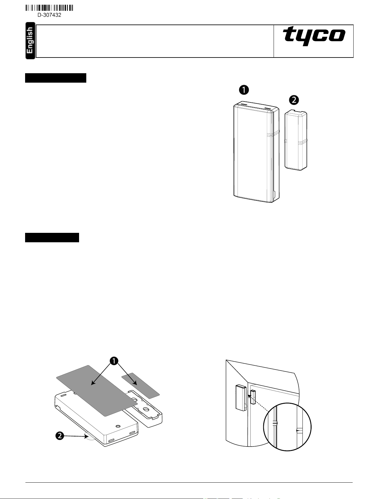
Figure 1: MC-303 PG2
1: Device
2:Magnet
2. Installation
Caut ion: Service personnel only may installthis equipment. Place this device in no-hazardous indoor locationsonly.
Notes:
Installthe MC-303 PG2 in accordance with the Standard for Installation and Classification of Bur glar and Holdup Alarm Systems, UL 681.
To comply with FCC and IC RF exposure compliance requirements, locate the device at a distance of at least 20 cm from all persons during normal
operation.
Do not co-locate the antennas used for this product, or operate them in conjunction with any other antenna or transmitter.
2.1. Mounting the device (quick installation)
1. Peelthe release liners off the two strips of double-sided adhesivetape and attach the tape to the back of the device and the magnet. See
Figure 2.
2. Place the device on the frame of a window or door and place the magnet on the moving surface of the door or window itself, directed
according to the location marks. See Figure 3.
Note: See section '3. TypicalReed Switch Positions' for more information on alignment.
Figure 2: Quick in stallation
1. Double-sided adhesive tape
Device and magnet posit ion on door and door frame
Figure 3:
2. Enrollment/battery tab
D-307432 MC-303 PG2 Installation Instructions 1
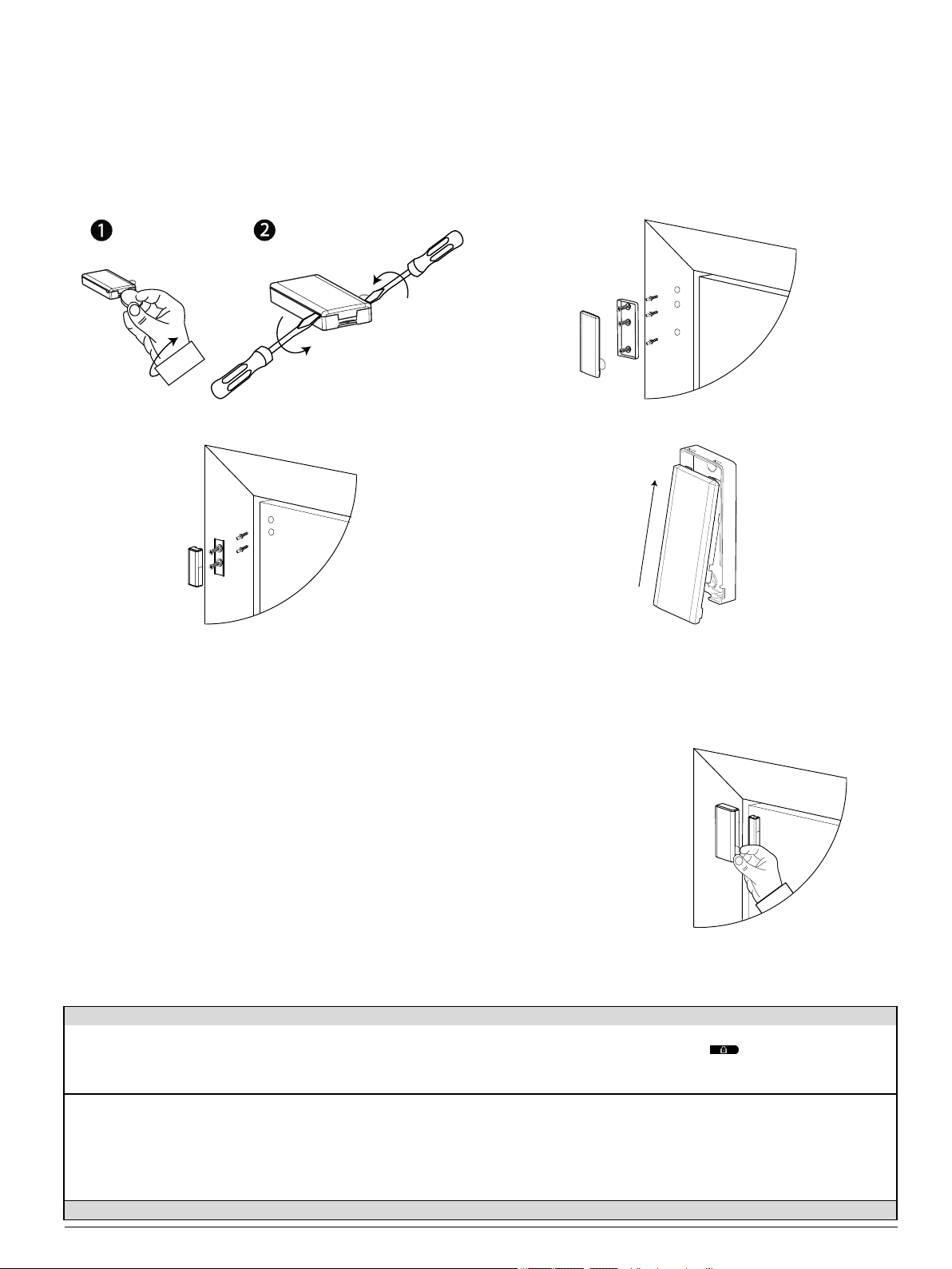
2.2. Mounting the device (screw installation)
To mount the device with screws, complete the following steps:
1. Insert a coin in the slot and twist to remove the cover. See Figure 4.1. If a coin is not available, insert a 4 mm flat screwdriver into each slot of the
plasticcover and twist to open each side. See Figure 4.2.
2. Screw the device base onto the door frame. See Figure 5.
3. Screw the magnet base on to the door. See Figure 6. Align the magnet and devicedirected according to the location marks. See Figure 3.
Note: See section '3. TypicalReed Switch Positions' for more information on alignment.
4. Clip the covers on to the device base and magnet base. See Figure 7.
Figure 4: Device cover removal Figure 5: Device screw installation
Figure 6: Magnet screw inst allation Figure 7: Closing the d evice cover
2.3. Enrolling the device
To enroll the device, complete the following steps:
1. Pull the battery/enrollment tab to power on the device. See F igure 8.
2. From the installation menu in the control panel, follow the flow chart below.
Notes:
Refer to the PowerMaster panel installer guide and select 02:ZONES/DEVICES from the installation
menu.
For UL/ULC listed installationsuse onlyin conjunction with UL/ULC listed control panels: PowerMaster10 PG2 and PowerMaster-30 PG2.
When enrolling an MC-303 PG2 detector to PowerMaster panels with version 19.4 or ear lier, enroll the
detector as MC-302 magnetic contact detector, ID:100-XXXX, and labeled Contact Sens in the panel.
Table 1: Enrollment flow chart
Step 1
From the installer
menu, select
02:ZONES/DEVICES
02:ZONES DEVICES >
ADD NEW DEVICES >
Step 2 Step 3 Step 4 Step 5 Step 6
Select ADD NEW
DEVICES.
Enroll the device or
enter the device ID.
ENROLL NOW or
ENTER
ID: XXX-XXXX >
Select the desired
zone number.
Z06: Contact
Sensor ID No.
100-XXXX
Configure the
location, zone type,
and chime
parameters.
Z06: LOCATION
Z06: ZONE TYPE
Z06: SET CHIME
Z06: DEV SETTINGS
Figure 8: Battery/enrollment tab
Configure the detector or select
, followed by OK to exit.
D-307432 MC-303 PG2 Installation Instructions
2

2.4. Replacing the battery
Caut ion: Do not replace the battery with an incorrect type as it may cause an explosion. Dispose of the used battery according to the manufacturer's
instructionsand according to local rules and regulations.
Warning:This pr oduct contains a coin battery. If it is swallowed, it can cause severe internal burns in just 2 hours and can lead to death. Keep new and
used batteries away from children. If the battery compartment does not close securely, stop using the product and keep it away form children. Seek
immediate medicalattention if you think batteries might have been swallowed or placed inside any par t of the body.
To remove the battery, complete the following steps:
1. Remove the device cover. See Figure 4.
2. Wedge a flat head screwdriver under the battery. See Figure 9
(a).
3. Twist the screwdr iver using the magnet base as a lever to
remove the battery.
To insert the battery, complete the following steps:
1. Insert the battery at an angle while observing battery polarity.
Note: When you insert the battery, the (+) symbol should be
visible and not the (-) symbol. See Figure 9 (b).
2. Pressdown on the battery untilit fitsinto place.
Figure 9: Battery removal and insertion
3. Typical reed switch positions
Table 1 displays the range coverage directions of the MC-303 PG2.
Table 2: T ypical reed switch positions
Wood Supp orts Iron
Opening Closing Direction Opening Closing
> 25 mm (0.98 in.) < 20 mm (0.79 in.) X > 9 mm (0.35 in.) < 5 mm (0.20 in.)
> 16 mm (0.63 in.) < 14 mm (0.55 in.) Y > 17 mm (0.67 in.) < 12 mm (0.47 in.)
> 27 mm (1.05 in.) < 25 mm (0.98 in.) Z > 18 mm (0.71 in.) < 15 mm (0.59 in.)
Figure 10:Ran ge coverage directio ns
4. Local diagnostics test
Separate the device cover from the base before testing and complete the following steps:
Note: For further instruction, see Mounting the device (screw installation), step 1.
1. Close the cover to return the tamper switch to its normal (undisturbed) position.
2. Open the door or window momentarily to verify detection. Red LED blinks will indicate detection.
3. Wait 2 secondsfor the LED to blink three times and compare the LED color to the reception result in Table 3.
Table 3: Sig nal st reng th indicat ion
LED response Reception
Green LED blinks Strong
Yellow LED blinks Good
Red LED blinks Poor
No blinks No communication
Important! Reliablereception must be assured. Therefore, poor signal strength is not acceptable. If you receive a poor signal from the detector, relocate it and re-test untila strong signal strength is received . In regions requiring UL-compliant installation, only strong signalstrength is permitted.
Note: A strong signalstrength is suggested. You must verify the signal strength using the control panel diagnostic test. For detailed diagnosticstest
instructions, refer to the control panel installer guide.
D-307432 MC-303 PG2 Installation Instructions
3

5. Specifications
Frequency Band (MHz)
Maximum Tx Power
Modulation
Antenn a
Communication Protocol
Supervision
Batt ery type
Batt ery Life
Low Battery Threshold
Operating Temperature
Storage Temperature
Relative Humidity (RH)
Dimensions (LxWxD)
Weight (including battery)
Colo r
6. Compliance with standards
The MC-303 PG2 complies with the follo wing standards:
Europe EN 300220, EN 301489, EN 50130-4, EN 61000-6-3, EN 62368-1, EN 50131-1, EN 50131-2-6 Grade 2, ClassII
and EN 50131-6 Type C
Hereby, Visonic Ltd. declares that the radio equipment type MC-303 PG2 is in compliance with Directive 2014/53/EU.
The full text of the EU declaration of conformity isavailable at the following internet address:
http://www.visonic.com/download-center.
USA: FCC- CFR 47 Part 15, UL- UL 634
433, 868, 915 (in accordance with the prevailing frequency of your region)
Note: Only devices in frequency band 915MHz are UL/ULC listed
10 dBm radiated @ 868 MHz, 915 MHz
-5 dBm radiated @ 433 MHz
GFSK
Built-in inverted-F antenna
PowerG
Signaling at 256 s intervals
3 V Lithium CR2450 Panasonic battery only
6 years with typical use at room temperature 25°C (77°F)
2 V at room temperature 25°C (77°F)
0°C (32°F ) to 50°C (122°F). UL verified range: 0ºC (32°F) to 49ºC (120°F ) only -20°C to
70°C (-4°F to 158°F)
Up to 95% non-condensing, UL verified up to a maximum of 85% RH only
67 x 31 x 11 mm (2.6 x 1.2 x 0.4 in.)
20 g (0.71 oz)
White or brown
Canada:IC-RSS-247, ULC – C634
The Power G peripheral devices have two-way c ommunication functionality, providing additional benefits as described in the technical
brochure. This functionality has not been tested to comply with the respective technical requirements and should therefore be considered
outside the s cope of the product's c ertification.
Security Grade:Designed according to EN 50131-1, EN-50131- 2-6 and EN-50131-6 Type C: this equipment can be applied
in installed systems up to and including Security Grade 2.
Environ ment Class:EN-50131-2-6 Class II
Not e: This equipment has been tested and found to complywith the limits for a ClassB digitaldevice,pursuant to part 15 of the FCC Rules. These limits
are designed to provide r easonable protection against harmful interference in a residentialinstallation. T his equipment generates, uses and can radiate
radio frequency energy and, if not installed and used in accordance with the instructions, may cause harmful interference to r adio communications.
However, there is no guarantee that interfer ence willnot occur in a particular installation. If this equipment does cause harmful interference to radio or
television reception, which can be determined by turning the equipment off and on, the user isencouraged to try to correct the interference by one or
more of the following measures:
-Reor ient or relocate the receiving antenna.
-Increase the separation between the equipment and receiver.
-Connect the equipment into an outlet on a circuit different from that to which the r eceiver isconnected.
-Consult the dealer or an experienced radio / TV technician for help.
Cet équipement a été testé et jugé conforme aux limites s’appliquant à un appareil numérique de classe B, conformément à la Partie 15 des
réglementations de la FCC. Ces limites ont été élaborées pour offrir une pr otection raisonnable contre lesinterferences nuisiblesdans une installation
résidentille.
l This Class B digital apparatus complieswith Canadian ICES-003.
l Cet appareil numerique de la classe B est conforme a la norme NMB-003 du Canada.
WARNING! Changes or modifications to this unit not expressly approved by the party responsible for compliance could void the user’s authority to
operate the equipment.
This device complies with Part 15 of the FCC Rules and with ISED license-exempt RSS standard(s). Operation is subject to the following two conditions:
(1) T his device may not cause harmful interference, and (2) this device must accept any interference received, including interference that may cause
undesired operation.
Le présent appareil est conforme aux CNR d'ISED applicablesaux appareils radio exempts de licence. L'exploitation est autor isée aux deux conditions
suivantes : (1) l'appareil ne doit pas pr oduire de brouillage, et (2) l'utilisateur de l'appareil doit accepter tout brouillage radioélectrique subi, même si le
brouillage est susceptible d'en compromettre le fonctionnement.
To comply with FCC and IC RF exposure compliance requirements, the device should be located at a distance of at least 20 cm from all persons during
normal operation. T he antennas used for this pr oduct must not be co-located or operated in conjunction with any other antenna or transmitter.
Le dispositif doit être placé à une distance d'au moins20 cm à partir de toutes lespersonnes au cours de son fonctionnement normal. Les antennes
D-307432 MC-303 PG2 Installation Instructions
4

utilisées pour ceproduit ne doivent pas être situés ou exploitésconjointement avec une autre antenne ou transmetteur .
7. Special comments
Even the most sophisticated detectors can sometimes be defeated or may fail to warn due to: DC power failure / improper connection, malicious
masking of the lens, tampering with the opticalsystem, decreased sensitivity in ambient temperatures close to that of the human body and unexpected
failure of a component part.
The above list includes the most common reasons for failure to detect intrusion, but is by no means comprehensive. It istherefor e recommended that
the detector and the entire alarm system be checked weekly,to ensure proper performance.
An alarm system should not be regarded as a substitute for insurance. Home and property owners or renters should be prudent enough to continue
insuring their lives and property, even though they are protected by an alarm system.
W.E.E.E. Product Recycling Declaration
For information regarding the recycling of this product you m ust contact the company from which youoriginally purchased i t. If you are discarding this product and not returning it for repair then
you must ensure that it is returned as i dentifiedby your supplier. This product is not to bethrown away with everyday waste.
Directive 2002/96/EC Waste Electrical andElectronic Equipment.
WARRANTY
Visonic Limited (the “Manufacturer") warrants thisproduct only ( the "Product") to the original purchaser only (the “Purchaser”) against defective
workmanship and materials under normal use of the Product for a period of twelve (12) months from the date of shipment by the Manufacturer.
This Warranty is absolutely conditional upon the Product having been properly installed, maintained and oper ated under conditions of normal use in
accordance with the Manufacturers recommended installation and operation instructions.Products which have become defective for any other r eason,
according to the Manufacturers discretion, such as improper installation, failure to follow recommended installation and operational instructions, neglect,
willfuldamage, misuse or vandalism, accidental damage, alteration or tampering, or repair by anyone other than the manufacturer, are not covered by
this Warranty.
There is absolutely no warranty on software, and allsoftware products are sold as a user license under the terms of the softwar e license agreement
included with such Product.
The Manufacturer does not represent that this Product may not be compromised and/or circumvented or that the Product will prevent any death and/or
personal injury and/or damage to property resulting from burglary, robbery, fire or otherwise, or that the Product willin all casesprovide adequate
warning or pr otection. The Product, properly installed and maintained, only reduces the risk of such events without warning and it is not a guar antee or
insurance that such events willnot occur.
Con dit ions to Void Warranty: This warranty appliesonly to defects in par ts and workmanship relating to normal use of the Products. It does not
cover:
* damage incurred in shipping or handling;
* damage caused by disaster such as fire, flood, wind, earthquake or lightning;
* damage due to causesbeyond the control of the Seller such as excessive voltage, mechanical shock or water damage;
* damage caused by unauthorized attachment, alterations, modifications or foreign objectsbeing used with or in conjunction with the Products;
* damage caused by peripherals (unlesssuch peripherals were supplied by the Seller;
* defects caused by failure to provide a suitable installation environment for the products;
* damage caused by use of the Products for purposes other than those for which they were designed;
* damage from improper maintenance;
* damage arising out of any other abuse, mishandling or improper application of the Products.
Items Not Covered by Warranty: In addition to the items which void the Warr anty, the following items shallnot be covered by Warranty: (i) freight cost
to the repair centre; (ii) customs fees, taxes,or VAT that may be due; (iii) Products which are not identified with the Seller's product label and lot number
or serial number; (iv) Products disassembled or repaired in such a manner asto adversely affect performance or prevent adequate inspection or testing
to verify any warranty claim. Access cards or tags returned for replacement under warranty willbe credited or replaced at the Seller's option.
THIS WARRANTY IS EXCLUSIVE AND EXPRESSLY IN LIEU OF ALL OTHER WARRANTIES, OBLIGATIONS OR LIABILITIES, WHETHER
WRITT EN, ORAL, EXPRESS OR IMPLIED, INCLUDING ANY WARRANTY OF MERCHANTABILITY OR FITNESS F OR A PARTICULAR
PURPOSE, OR OTHERWISE. IN NO CASE SHALL THE MANUFACTURER BE LIABLE TO ANYONE FOR ANY CONSEQUENTIAL OR
INCIDENTAL DAMAGES FOR BREACH OF THIS WARRANT Y OR ANY OTHER WARRANTIES WHATSOEVER, AS AFORESAID.
THE MANUFACT URER SHALL IN NO EVENT BE LIABLE FOR ANY SPECIAL, INDIRECT, INCIDENTAL, CONSEQUENTIAL OR PUNIT IVE
DAMAGES OR FOR LOSS, DAMAGE, OR EXPENSE, INCLUDING LOSS OF USE, PROFITS, REVENUE, OR GOODWILL, DIRECTLY OR
INDIRECTLY ARISING FROM PURCHASER’S USE OR INABILITY TO USE T HE PRODUCT, OR FOR LOSS OR DESTRUCTION OF OTHER
PROPERTY OR FROM ANY OTHER CAUSE, EVEN IF MANUFACTURER HAS BEEN ADVISED OF THE POSSIBILITY OF SUCH DAMAGE.
THE MANUFACT URER SHALL HAVE NO LIABILITY FOR ANY DEATH, PERSONAL AND/OR BODILY INJURY AND/OR DAMAGE TO
PROPERTY OR OTHER LOSS WHETHER DIRECT, INDIRECT, INCIDENT AL, CONSEQUENTIAL OR OTHERWISE, BASED ON A CLAIM THAT
THE PRODUCT FAILED TO FUNCTION. HOWEVER, IF THE MANUFACTURER IS HELD LIABLE, WHETHER DIRECTLY OR INDIRECTLY,
FOR ANY LOSS OR DAMAGE ARISING UNDER THIS LIMITED WARRANTY, THE MANUFACT URER'S MAXIMUM LIABILITY (IF ANY) SHALL
NOT IN ANY CASE EXCEED THE PURCHASE PRICE OF THE PRODUCT INVOLVED, WHICH SHALL BE FIXED AS LIQUIDATED DAMAGES
AND NOT AS A PENALTY, AND SHALL BE THE COMPLETE AND EXCLUSIVE REMEDY AGAINST THE MANUFACTURER. SOME
JURISDICT IONS DO NOT ALLOW THE EXCLUSION OR LIMITATION OF INCIDENTAL OR CONSEQUENTIAL DAMAGES, SO THESE
LIMITATIONS MAY NOT APPLY UNDER CERTAIN CIRCUMSTANCES.
When accepting the delivery of the Product, the Pur chaser agrees to the said conditions of sale and warranty and he recognizeshaving been informed
of.
The Manufacturer shall be under no liability whatsoever arising out of the corruption and/or malfunctioning of any telecommunication or electronic
equipment or any programs.
The Manufacturers obligationsunder this Warranty ar e limited solelyto repair and/or replace at the Manufacturer’s discretion any Product or part
thereof that may prove defective. Any repair and/or replacement shall not extend the original Warr anty period. The Manufacturer shall not be
responsible for dismantling and/or reinstallation costs. To exercise this War ranty the Product must be returned to the Manufacturer freight pre-paid and
insured. Allfreight and insurance costsare the responsibility of the Purchaser and are not included in this Warranty.
D-307432 MC-303 PG2 Installation Instructions
5

This warranty shall not be modified, varied or extended, and the Manufacturer does not authorize any person to act on its behalf in the modification,
variation or extension of this warranty. This warranty shall apply to the Product only. All products, accessories or attachments of others used in
conjunction with the Product, including batteries, shall be covered solelyby their own warranty, if any. T he Manufacturer shall not be liable for any
damage or loss whatsoever, whether directly,indirectly,incidentally, consequentiallyor otherwise, caused by the malfunctionof the Product due to
products, accessories, or attachments of others, including batteries, used in conjunction with the Products. This War ranty is exclusive to the original
Purchaser and is not assignable.
This Warranty is in addition to and does not affect your legal rights. Any provision in this warranty which is contrary to the Law in the state or country were
the Product is supplied shall not apply.
Governing Law: This disclaimer of warranties and limited warranty are governed by the domesticlaws of Israel.
Warning
The user must follow the Manufacturer’s installation and operational instructions including testing the Product and its whole system at leastonce a week
and to take all necessary precautions for his/her safety and the protection of his/her property.
* In case of a conflict, contradiction or interpretation between the English version of the war ranty and other versions, the English version shallprevail.
4/18
EMAIL: info@visonic.com
INTERNET: www.visonic.com
TYCO SECURITY PRODUCTS LTD. 2018D-307432MC-303 PG2
REV. 0, (09/18)
D-307432 MC-303 PG2 Installation Instructions
6
 Loading...