

Page 1
MC-302 PG2
Supervised PowerG Magnetic Contact Device
1. INTRODUCTION
The MCT-302 PG2 is a fully supervised, PowerG magnetic
contact device. The device includes a built-in reed switch (that
opens upon removal of a magnet placed near it). The MC-302 PG
sends the parameters of the specific alarm to the control panel
using PowerG 2-way communications protocol.
The MC-302 PG 2 tamper switch is activated when the cover is
removed.
A periodic supervision message is transmitted automatically. The
control panel is thus informed, at regular intervals, of the unit’s
active participation in the system.
An LED lights whenever alarm or
tamper events are reported. The
LED does not light while a
supervision message is being
transmitted.
Operating power is obtained from
an on-board 3 V Lithium battery.
When the battery voltage is low, a
“low battery” message is sent to
the receiver.
2. SPECIFICATIONS
Frequency Band (MHz): Europe: 433, 868, USA: 915
Modulation: GFSK
Antenna: Built-in helical antenna.
Communication Protocol: PowerG.
Alarm Input: One internal.
Supervision: Signaling at 4-min. intervals.
Tamper Alert: Reported when a tamper event occurs.
Battery type
Sanyo only.
Caution!
Risk of explosion if battery is replaced by an incorrect type.
Dispose of used battery according to manufacturer's instructions.
Battery Life Expectancy
Battery Supervision: Automatic transmission of battery condition
data as part of periodic status report and immediately upon low
battery condition detection.
Operating Temperature: 0°C to 49°C (32°F to 120°F).
Dimensions: 81 x 34 x 25 mm (3-3/16 x 1-1/4 x 1 in.)
: 3 V Lithium CR-123 type battery, Panasonic or
: 8 years (for typical use)
Weight: 53g (1.9 oz)
Compliance with Standards:
USA: CFR47 part 15 (FCC)
Europe: EN 301 489-3, EN 50130-4:( 95) & A1 : (98) & A2: (03),
EN 300 220-2, EN 60950-1, EN 50130-5, EN 50131-1, CLC/TS
50131-2-6
Canada: RSS 210
This device complies with Part 15 of the FCC Rules and RSS-210
of Industry and Science Canada. Operation is subject to the
following two conditions: (1) This device may not cause harmful
interference, and (2) this device must accept any interference
received, including interference that may cause undesired
operation.
This device complies with the essential requirements and
provisions of Directive 1999/5/EC of the European Parliament
and of the Council of 9 March 1999 on radio and
telecommunications terminal equipment.
Installation Instructions
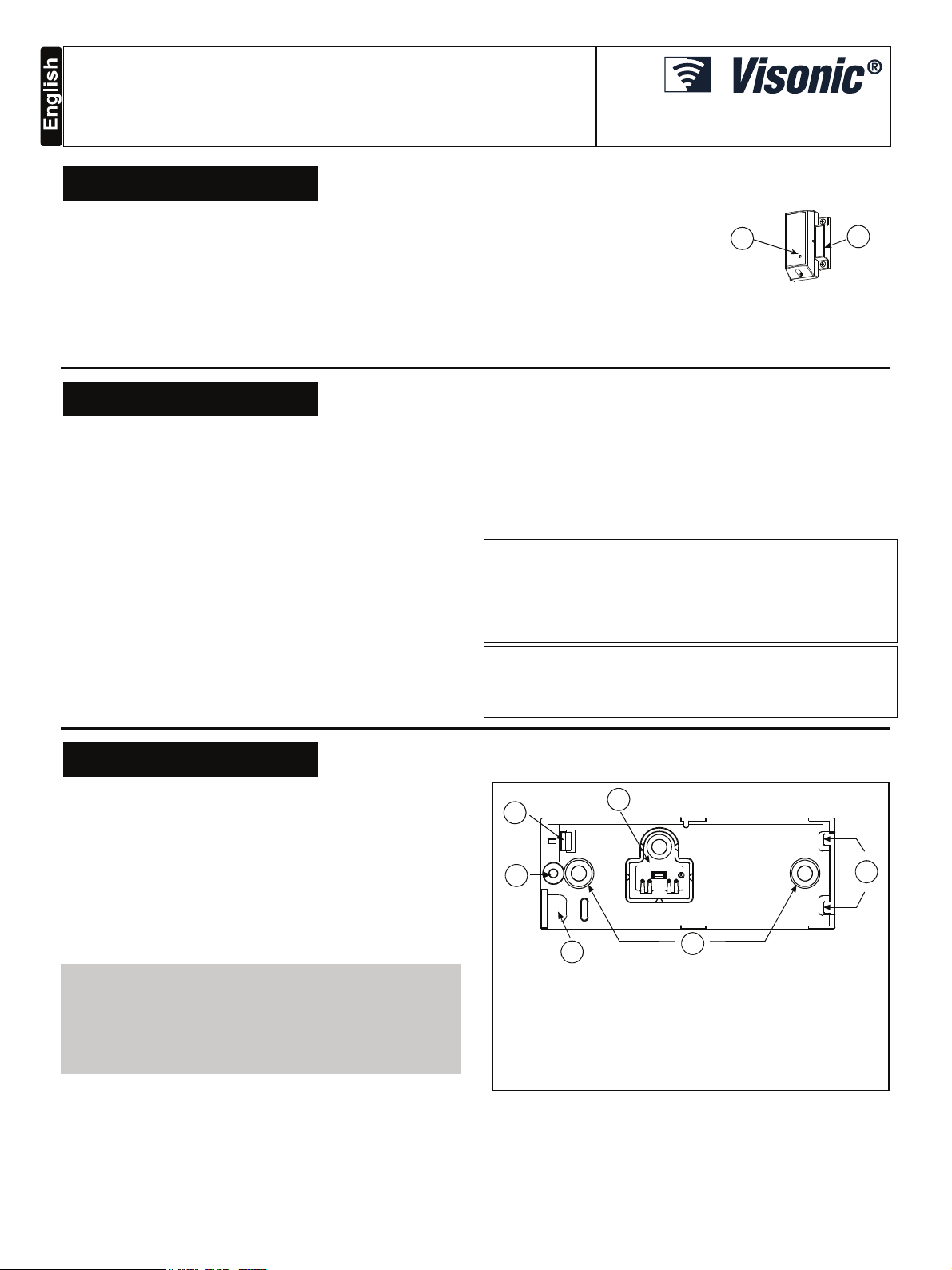
A
A. Transmission LED
B. Magnet
Figure 1:
External View
B
3. INSTALLATION
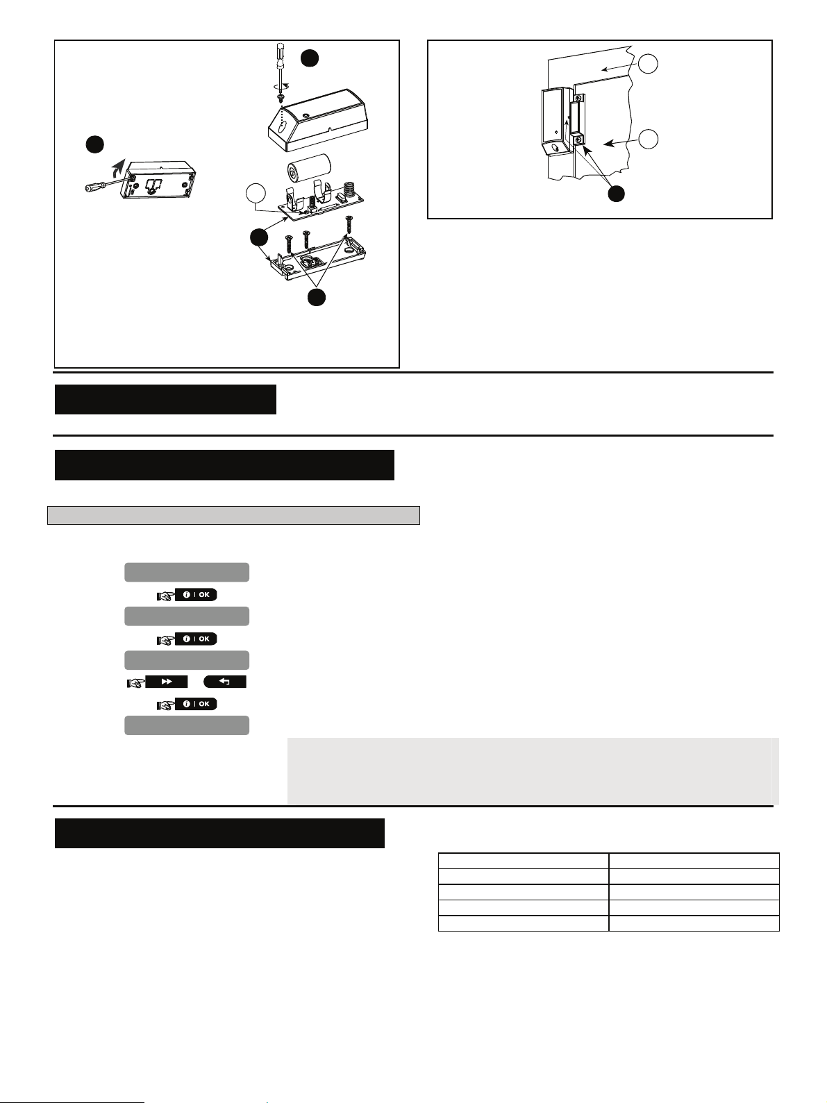
3.1 Mounting (Fig. 3a and 3b)
It is highly recommended to attach the transmitter to the top of the
door/window on the fixed frame and the magnet to the movable
part (door or window). Make sure that the magnet is located not
more than 6 mm (0.25 in.) from the transmitter’s marked side.
Note: Once the cover is removed, a tamper message is
transmitted to the receiver. Subsequent removal of the battery
prevents transmission of "TAMPER RESTORE", leaving the
receiver in permanent alert. To avoid this, during the enrolling
process, press the tamper switch while you remove the battery.
Attention! The unit has a back tamper switch (optional) under
the PCB. As long as the PCB is seated firmly within the base, the
switch lever will be pressed against a special break-away base
segment that is loosely connected to the base (Figures 2 and 3a).
Be sure to fasten the break-away segment to the wall. If the
detector unit is forcibly removed from the wall, this segment will
break away from the base, causing the tamper switch to open.
A
B
F
E
A. Flexible Retainer
B. Break-away base segment (for Back Tamper)
C. P.C. board edge supports
D. Mounting holes
E. Wiring inlet
F. Plastic standoff for case closure screw
Figure 2. Base with P.C. Board Removed
D
C
D-302412 1
Page 2
1
A
A
D
L
B
2
A
C
5
Figure 3b. Mounting
3
Figure 3a. Mounting
Note: 868 MHz device is illustrated in the above example. The
same mounting procedure should be performed for 433 MHz and
915 MHz devices.
* This screw is used for back tamper only.
*
4
1. Remove screw
2. Separate base from cover.
3. Flex catch and remove P.C. board
4. Mark & drill 2 holes in mounting surface.
Fasten base with 2 countersunk screws.
5. Mount the magnet near its location mark with 2 screws
A. Enroll button
B. Fixed frame
C. Moving part
4. ENROLLMENT
Refer to the PowerMaster-10 Installer Guide for the device enrollment procedure.
5. MODIFY DEVICE SETTINGS
This section describes how to configure the parameters of contact sensors from the PowerMaster-10 control panel.
To Modify the Contact Sensor Settings
Refer to the PowerMaster-10 Installer Guide and perform the procedure for Adding A Wireless Device (section 4.5.2), or, Modifying a
Device (section 4.5.5). Then continue below to modify the device settings.
1.
2.
3.
4.
EV SETTINGS
larm LED
ED ON
or
larm LED
Here you determine whether or not the alarm LED indication will be activated.
Select between "LED ON" and "LED OFF".
When exiting "
devices that need to be updated, as follows: DEV UPDATING NNN.
For detailed instructions on Adding Devices, Deleting Devices, Replacing Devices and
Defining Defaults see the PowerMaster-10 Installer Guide.
ZONES / DEVICES
" menu, the PowerMaster-10 system displays the number of
6. LOCAL DIAGNOSTICS TEST
Before testing, separate the base from the cover (see Fig. 3a).
A. Press the tamper switch once and release it.
B. Put back the cover to return the tamper switch to its normal
(undisturbed) position, and then secure the front cover to the
base with the case closure screw.
C. Momentarily open the door or window and verify the red LED
blinks, indicating detection.
D. After 2 seconds the LED blinks 3 times.
The following table indicates received signal strength
indication.
IMPORTANT! Reliable reception must be assured. Therefore,
"poor" signal strength is not acceptable. If you receive a "poor"
signal from the device, re-locate it and re-test until a "good" or
"strong" signal strength is received.
Note: For detailed Diagnostics Test instructions refer to
PowerMaster-10 Installer Guide.
2 D-302412
LED response Reception
Green LED blinks Strong
Orange LED blinks Good
Red LED blinks Poor
No blinks No communication
Page 3

7. MISCELLANEOUS COMMENTS
Visonic Ltd. wireless systems are very reliable and are tested to
high standards. However, due to low transmitting power and
limited range (required by FCC and other regulatory authorities),
there are some limitations to be considered:
A. Receivers may be blocked by radio signals occurring on or
near their operating frequencies, regardless of the digital code
used.
.
B. A receiver responds only to one transmitted signal at a time.
C. Wireless devices should be tested regularly to determine
whether there are sources of interference and to protect
against faults.
The user is cautioned that changes or modifications to the
unit, not expressly approved by Visonic Ltd., could void the
user’s FCC or other authority to operate the equipment.
D-302412 3
Page 4

WARRANTY
Visonic Limited (the “Manufacturer") warrants this product only (the "Product") to the original purchaser only (the
“Purchaser”) against defective workmanship and materials under normal use of the Product for a period of twelve
(12) months from the date of shipment by the Manufacturer.
This Warranty is absolutely conditional upon the Product having been properly installed, maintained and operated
under conditions of normal use in accordance with the Manufacturers recommended installation and operation
instructions. Products which have become defective for any other reason, according to the Manufacturers
discretion, such as improper installation, failure to follow recom mended installation and operational instructions,
neglect, willful damage, misuse or vandalism, acc idental damage, alteration or tampering, or repair by anyone
other than the manufacturer, are not covered by this Warranty.
The Manufacturer does not represent that this Product may not be compromised and/or circumvented or that the
Product will prevent any death and/or personal injury and/or damage to property resulting from burglary, robbery,
fire or otherwise, or that the Product will in all cases provide adequate warning or protection. The Product,
properly installed and maintained, only reduces the risk of such events without warning and it is not a guarantee
or insurance that such events will not occur.
THIS WARRANTY IS EXCLUSIVE AND EXPRESSLY IN LIEU OF ALL OTHER WARRANTIES, OBLIGATIONS
OR LIABILITIES, WHETHER WRITTEN, ORAL, EXPRESS OR IMPLIED, INCLUDING ANY WARRANTY OF
MERCHANTABILITY OR FITNESS FOR A PARTICULAR PURPOSE, OR OTHERWISE. IN NO CASE SHALL
THE MANUFACTURER BE LIABLE TO ANYONE FOR ANY CONSEQUENTIAL OR INCIDENTAL DAMAGES
FOR BREACH OF THIS WARRANTY OR ANY OTHER WARRANTIES WHATSOEVER, AS AFORESAID.
THE MANUFACTURER SHALL IN NO EVENT BE LIABLE FOR ANY SPECIAL, INDIRECT, INCIDENTAL,
CONSEQUENTIAL OR PUNITIVE DAMAGES OR FOR LOSS, DAMAGE, OR EXPENSE, INCLUDING LOSS
OF USE, PROFITS, REVENUE, OR GOODWILL, DIRECTLY OR INDIRECTLY ARISING FROM
PURCHASER’S USE OR INABILITY TO USE THE PRODUCT, OR FOR LOSS OR DESTRUCTION OF
OTHER PROPERTY OR FROM ANY OTHER CAUSE, EVEN IF MANUFACTURER HAS BEEN ADVISED OF
THE POSSIBILITY OF SUCH DAMAGE.
THE MANUFACTURER SHALL HAVE NO LIABILITY FOR ANY DEATH, PERSONAL AND/OR BODILY
INJURY AND/OR DAMAGE TO PROPERTY OR OTHER LOSS WHETHER DIRECT, INDIRECT, INCIDENTAL,
CONSEQUENTIAL OR OTHERWISE, BASED ON A CLAIM THAT THE PRODUCT FAILED TO FUNCTION.
W.E.E.E. Product Recycling Declaration
For information regarding the recycling of this product you must contact the company from which you orignially purchased it. If you are discarding this product and not
returning it for repair then you must ensure that it is returned as identified by your supplier. This product is not to be thrown away with everyday waste.
Directive 2002/96/EC Waste Electrical and Electronic Equipment.
However, if the Manufacturer is held liable, whether directly or indirectly, for any loss or damage arising under this
limited warranty, THE MANUFACTURER'S MAXIMUM LIABILITY (IF ANY) SHALL NOT IN ANY CASE
EXCEED THE PURCHASE PRICE OF THE PRODUCT, which shall be fixed as liquidated damages and not as a
penalty, and shall be the complete and exclusive remedy against the Manufacturer.
When accepting the delivery of the Product, the Purchaser agrees to the said c onditions of sale and warranty and
he recognizes having been informed of.
Some jurisdictions do not allow the exclusion or limitation of incidental or c onsequential damages, so these
limitations may not apply under certain circumstances.
The Manufacturer shall be under no liability whatsoever arising out of the corruption and/or m alfunctioning of any
telecommunication or electronic equipment or any programs.
The Manufacturers obligations under this W arranty are limited solely to repair and/or replace at the
Manufacturer’s discretion any Product or part ther eof that may prove defective. Any repair and/or replacement
shall not extend the original Warranty period. The Manufacturer shall not be responsible for dismantling and/or
reinstallation costs. To exercise this Warranty the Product must be returned to the Manufacturer f reight pre-paid
and insured. All freight and insurance costs are the responsibility of the Purchaser and are not included in this
Warranty.
This warranty shall not be modified, varied or extended, and the Manufacturer does not authorize any person to
act on its behalf in the modification, variation or extension of this warranty. This warranty shall apply to the
Product only. All products, accessories or attachments of others used in conjunction with the Product, including
batteries, shall be covered solely by their own warranty, if any. The Manufacturer shall not be liable for any
damage or loss whatsoever, whether directly, indirectly, incidentally, consequentially or otherwise, caused by the
malfunction of the Product due to products, ac cessories, or attachments of others, including batteries, used in
conjunction with the Products. This Warranty is exclusive to the original Purchaser and is not assignable.
This Warranty is in addition to and does not af fect your legal rights. Any provision in this warranty which is
contrary to the Law in the state or country were the Product is supplied shall not apply.
Warning:
The user must follow the Manufacturer’s installation and operational instructions including testing the
Product and its whole system at least once a week and to take all necessary precautions for his/her s afety and
the protection of his/her property.
1/08
VISONIC LTD. (ISRAEL): P.O.B 22020 TEL-AVIV 61220 ISRAEL. PHONE: (972-3) 645-6789, FAX: (972-3) 645-6788
VISONIC INC. (U.S.A.): 65 WEST DUDLEY TOWN ROAD, BLOOMFIELD CT. 06002-1376. PHONE: (860) 243-0833, (800) 223-0020.
FAX: (860) 242-8094
VISONIC LTD. (UK): UNIT 6 MADINGLEY COURT CHIPPENHAM DRIVE KINGSTON MILTON KEYNES MK10 0BZ. TEL: (0870) 7300800
FAX: (0870) 7300801. TEL: (0870) 7300800 FAX: (0870) 7300801 PRODUCT SUPPORT: (0870) 7300830
VISONIC GmbH (D-A-CH): KIRCHFELDSTR. 118, D-40215 DÜSSELDORF, TEL.: +49 (0)211 600696-0, FAX: +49 (0)211 600696-19
VISONIC IBERICA: ISLA DE PALMA, 32 NAVE 7, POLÍGONO INDUSTRIAL NORTE, 28700 SAN SEBASTIÁN DE LOS REYES, (MADRID), ESPAÑA.
TEL (34) 91659-3120, FAX (34) 91663-8468. www.visonic-iberica.es
INTERNET: www.visonic.com
©VISONIC LTD. 2010 MC-302 PG2 D-302412 (REV. 0, 11/10)
4 D-302412
 Loading...