

Page 1
KP-140 PG2
Portable Remote Wireless 2-Way Keypad
1. INTRODUCTION
KP-140 PG2 is a wireless keypad for the PowerG family control
panels. KP-140 PG2 enables the user to arm/disarm the alarm
system, to initiate emergency/fire/panic alarms, to perform one of
the AUX (auxiliary) functions (see Note 4 in Section 6) and to turn
lighting devices on and off. The keypad comprises an RF
transmitter that sends out a differently coded RF signal for each
command. The KP-140 PG2 comprises a proximity reader for
operation with a proximity tag.
The KP-140 PG2 supports an optional partition feature.
Partitioning allows you to have up to three independently
controllable areas with different user codes assigned to each
partition or one user code assigned to up to three partitions. A
partition can be armed or disarmed regardless of the status of the
other partitions within the system.
Note: Partition refers to the PowerG family control panels that
support the Partitioning feature.
The KP-140 PG2 enables activation of the Aux (Auxiliary), fifteen
home control outputs (X-10), one PGM output, Fire and
Emergency functions. Each button needs to be individually
defined for the AUX, PGM or X-10 functions at the corresponding
points of the "DEFINE PANEL" and "DEFINE OUTPUTS" menu of
the control panel (refer to the PowerMaster Installer Guide for
specific details).
An "on-board" tamper switch opens when the battery
compartment cover is removed, and an "under-board" tamper
switch opens if the unit is removed from its mounting place.
The main features of the KP-140 PG2 are:
• Status, alarm memory, and trouble data retrieval from the
control panel
• Automatic reporting of low battery voltage.
• Visual indications by red/green LED.
• Keypad back lighting.
• Various buzzer sounds in response to specific actions.
• Back tamper and battery compartment tamper
• Automatic supervision messages to the control panel.
• Exit/entry beeps
• Long-life 4 year (with entry/exit beeps) / 5 year (without
entry/exit beeps) battery life expectancy, 3 VDC lithium
battery.
• Wall mounting option.
User’s Guide
Communication Indications
Description Definition
Red LED lights shortly, then red LED lights 1
sec. and "sad" beep is heard
Red LED lights shortly, then green LED
lights 1 sec. and "happy" beep is heard
Red LED lights shortly and no buzzer sound
is heard.
Keypad Buzzer Sound
Description Symbol
Short single beep, upon pressing a button
"Happy" (success) beep
"Sad" (failure) beep
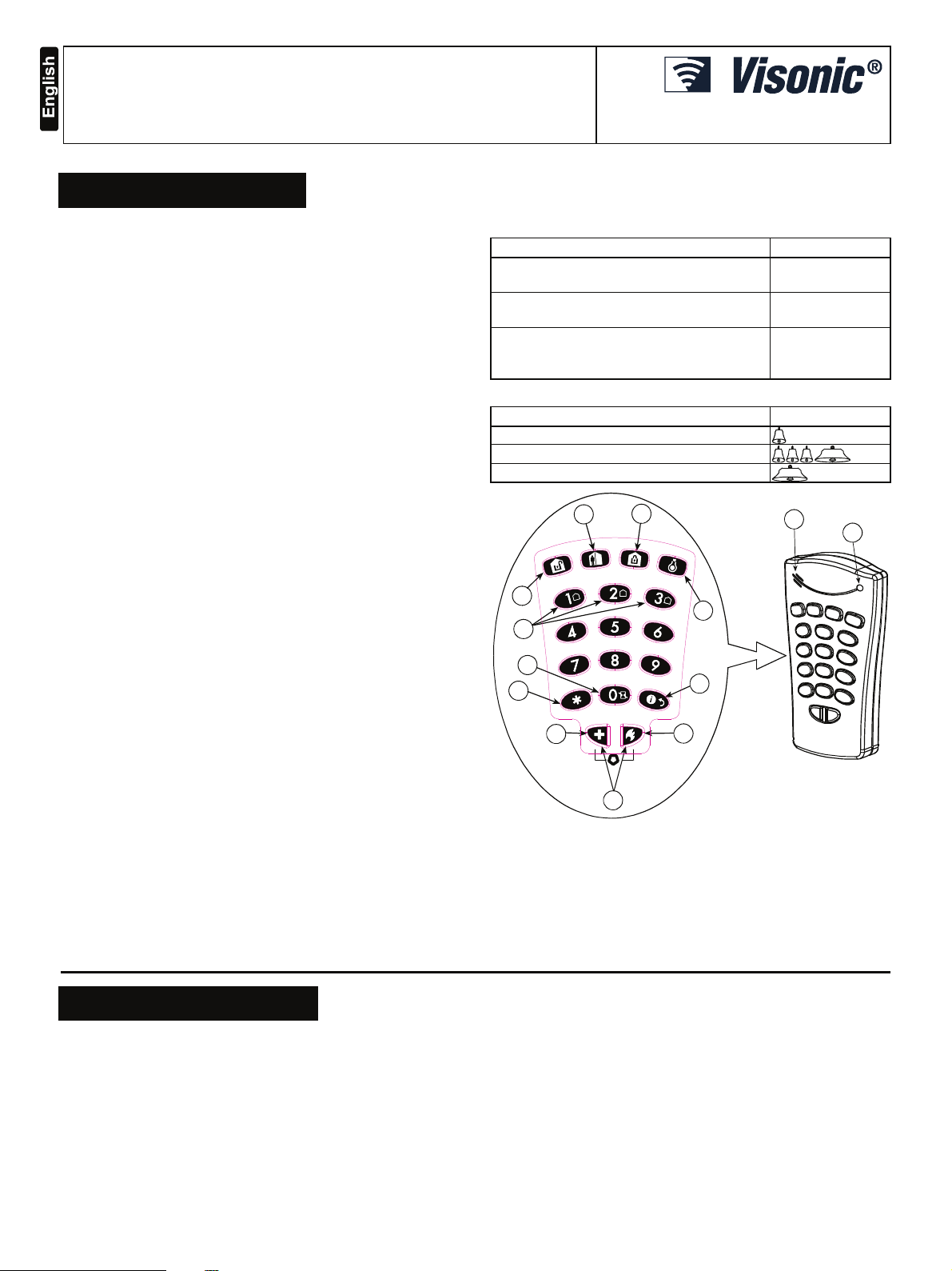
A
B
C
D
E
F
H
I
G
J
K
A. HOME
B. AWAY
C. DISARM J. FIRE
D. LIGHT K. PANIC
E. PARTITION SELECTION L. Buzzer
F. INSTANT M. LED
G. STATUS / ESCAPE
Figure 1 - External View
H. AUX / ENROLLMENT
I. EMERGENCY
Failure response
Success response
No communication
with the control
panel
L
M
2. SPECIFICATIONS
Frequency Band (MHz): Europe: 433, 868, USA: 915
Modulation: GFSK.
Antenna: Built-in antenna
Communication Protocol: PowerG
Battery type: 3V, CR123A type.
Caution!
Risk of explosion if battery is replaced by an incorrect type.
Dispose of used battery according to manufacturer's instructions.
Battery Life Expectancy: 4 years (with entry/exit beeps) /
5 years (without entry/exit beeps).
Operating Temperature: 0°C to 49°C (32°F to 120°F)
D-303015 1
Dimensions (LxWxD): 127x70x24mm (5 x 2-3/4 x 31/32 in)
Weight (including battery): 107g (3.4 oz)
Color: White
Compliance with Standards:
Europe
EN 300220-1, EN 50130-4, EN 50131-1 Grade 2 Class II, EN 50131-3,
EN 301489.
USA
CFR 47 part 15, Canada RSS 210
Page 2
3. MOUNTING AND BATTERY REPLACEMENT
B
T
O
E
-
E
O
S
D
D
1
2
A
A
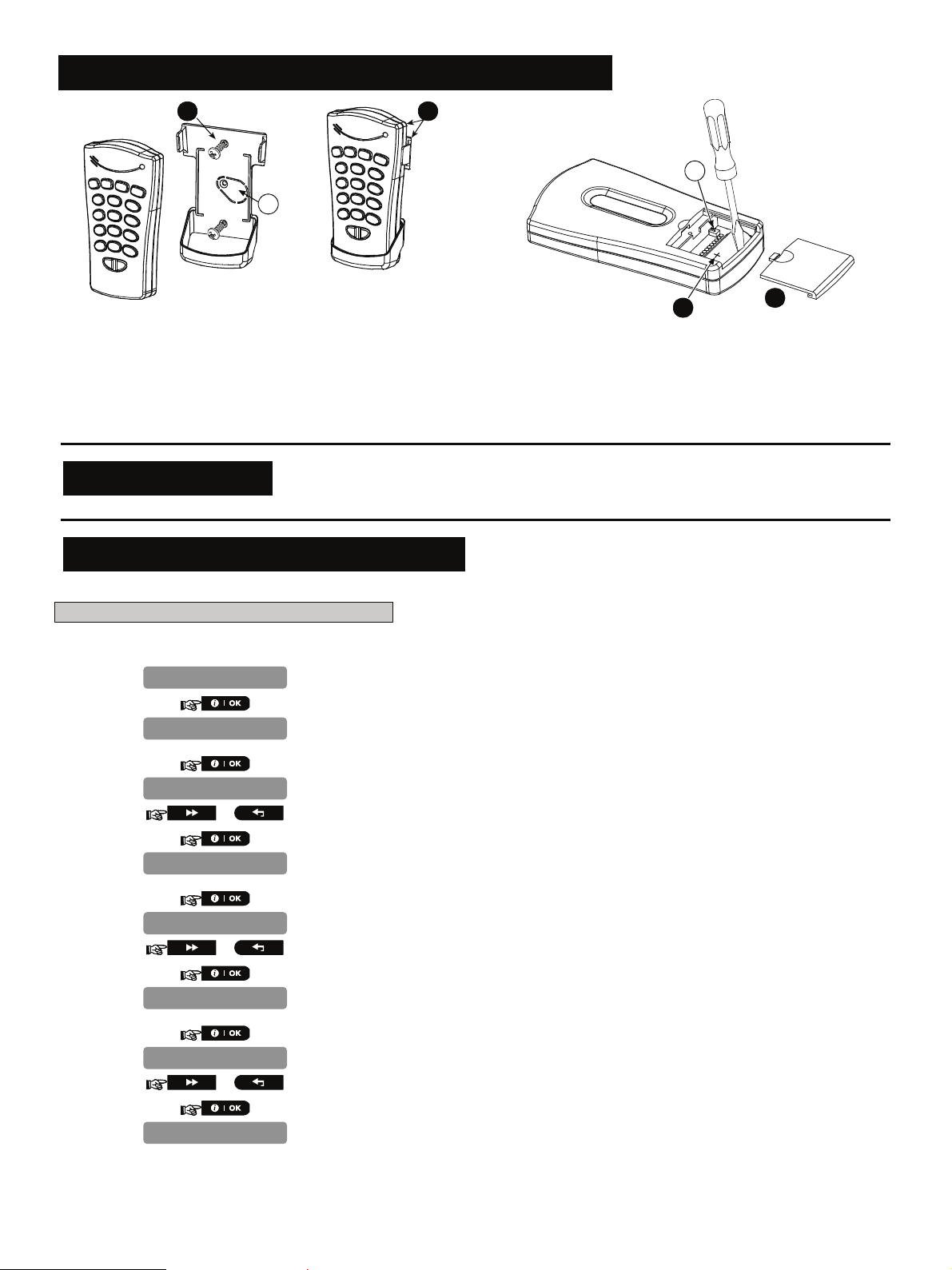
1. Drill 2 holes in mounting surface, insert wall anchors and fasten
the bracket with 2 screws.
2. Slide the keypad into the bracket.
A. Magnet (activates back tamper when bracket is removed from
the wall).
Figure 2 - Mounting
Note: If the KP-140 is mounted near the site door, the PowerG family control panel "Quick arming" function should be disabled,
otherwise site security may be compromised.
1. Slide out the cover.
2. Replace the battery (verify proper polarity) and close the cover.
A. Battery compartment tamper switch
Figure 3 - Battery Replacement
2
1
4. ENROLLMENT
Refer to the PowerMaster-10 Installer Guide for the device enrollment procedure.
5. MODIFY DEVICE SETTINGS
This section describes how to configure the parameters of the keypad from the PowerMaster-10 control panel.
To Modify the Keypad Device Settings
Refer to the PowerMaster-10 Installer Guide and perform the procedure for Adding A Wireless Device (section 4.5.2), or, Modifying a
Device (section 4.5.5). Then continue below to modify the device settings.
1.
2.
3.
4.
5.
6.
7.
8.
9.
10.
EV SETTINGS
AMPERS
isabled
or
UPERVISION
N
or
XIT
NTRY Beeps
N
or
UTTON (*)
Here you determine whether or not the tamper alarm will be activated and if so whether it
will be a wall tamper alarm or a battery tamper alarm.
Select between "Disabled", "Wall Only" or "Battery Only".
Here you determine whether or not the control panel will monitor supervision messages
sent by the KP-140 PG2 device.
Select between "ON" and "OFF".
Here you determine whether or not to activate the exit – entry beeps, or, activate the exit – entry
beeps when armed AWAY only.
Select between "ON", "OFF" and "OFF @ Home".
Here you select the function of the AUX button on the keypad device. Four options are
offered:
Not used: No functions assigned to AUX button.
Stop Beeps: Pressing the AUX button will cause the control panel and the KP-140 PG2
device to mute the beeps.
Skip exit delay: Pressing the AUX button will immediately stop the exit delay.
2 D-303015
Page 3

PGM: Pressing the AUX button will activate the PGM output (for further programming
N
instructions see the PowerMaster-10 Installer Guide section 4.12 CONFIGURING
OUTPUT PARAMETERS).
11.
12.
13.
ot used
or
Select between "Not Used", "Stop Beeps", "Skip exit delay" and "PGM".
When exiting "
INSTALLLER MODE
number of devices that need to be updated, as follows: "
For detailed instructions on Adding Devices, Deleting Devices, Replacing Devices and
Defining Defaults see the PowerMaster-10 Installer Guide.
6. OPERATION
The tables in the following sections describe how to activate the
various functions of the KP-140 PG2 keypad.
Security
Function Actions
Partition Selection (when
Partition is enabled)
Arming HOME
Arming AWAY
Disarming
Quick arm / HOME
Quick arm / AWAY
Instant (perform HOME/ AWAY arming)
Latchkey
Duress
AUX Function
Status
(perform arm AWAY)
default)
/ /
[user code]
[user code]
[user code]
(≈ 2 sec.)
(≈ 2 sec.)
(2)
(3)
[duress code]
(4)
(5)
(2580 by
Automation
Function Actions
X-10 device ON
X-10 device OFF
X-10 device toggle
PGM device ON
PGM device OFF
PGM device toggle
X-10 or PGM device
status
[X-10 no. 01 to 15]
[X-10 no. 01 to 15]
[X-10 no. 01 to 15]
[00]
[00]
[00]
[00 to 15]
(1)
" menu, the PowerMaster-10 system displays the
DEV UPDATING NNN
".
Safety
Function Actions
Emergency alarm
(≈ 2 sec.)
Fire alarm
Panic alarm
(≈ 2 sec.)
(≈ 2 sec.)
Notes
1. For arming HOME/AWAY a specific Partition, first press the
Partition number and then perform the arming action.
2. For INSTANT arming function, press the HOME/AWAY
button, enter the user code while the HOME/AWAY button
blinks, wait for success acknowledgement (green LED lights
and "happy" beep is heard), then press the INSTANT button.
3. For LATCHKEY arming function by arming AWAY / quick arm
away, wait for success acknowledgement (green LED lights
and "happy" beep is heard), then press the AWAY button
twice.
Note: Immediately after performing arming AWAY of the
system, you can perform the Latchkey and Instant functions,
one after the other.
4. The function of the AUX button can be configured on the
control panel (see section 5.)
STATUS button has two functions; pressing
5. The
the
sequence, or, when the KP-140 PG2 is in idle mode, it
displays the status of the control panel. Pressing the
provides the status of the control panel and is indicated when
the
provides indication on the status of the control panel (see
table below). If Partition is enabled, the partition no.
(
/ / button and the LED provides indication
on the status of the indicated partition no.
returns the KP-140 PG2 to idle mode from any
button, when the KP-140 PG2 is in idle mode,
/ / button lights steadily and the LED
/ / )
lights steadily in parallel to the
D-303015 3
Page 4

Control Panel Status
Description Definition
LED lights green 4 sec. Ready
LED lights red 4 sec. Not Ready
LED lights green 2 sec. and then yellow
2 sec.
LED lights red 2 sec. and then yellow 2
sec.
Ready + Trouble /
Memory (or both)
Not Ready + Trouble
/ Memory (or both)
6. Pressing a non-valid code causes a long failure beep.
7. If a keying sequence is not completed within timeout,
indicated when the pressed button stops blinking, the desired
function will not be executed.
WARRANTY
Visonic Limited (the “Manufacturer") warrants this product only (the "Product") to the
original purchaser only (the “Purchaser”) against defective workmanship and materials
under normal use of the Product for a period of twelve (12) months from the date of
shipment by the Manufacturer.
This Warranty is absolutely conditional upon the Product having been properly installed,
maintained and operated under conditions of normal use in accordance with the
Manufacturers recommended installation and operation instructions. Products which
have become defective for any other reason, according to the Manufacturers discretion,
such as improper installation, failure to follow recommended installation and operational
instructions, neglect, willful damage, misuse or vandalism, accidental damage, alteration
or tampering, or repair by anyone other than the manufacturer, are not covered by this
Warranty.
The Manufacturer does not represent that this Product may not be compromised and/or
circumvented or that the Product will prevent any death and/or personal injury and/or
damage to property resulting from burglary, robbery, fire or otherwise, or that the
Product will in all cases provide adequate warning or protection. The Product, properly
installed and maintained, only reduces the risk of such events without warning and it is
not a guarantee or insurance that such events will not occur.
THIS WARRANTY IS EXCLUSIVE AND EXPRESSLY IN LIEU OF ALL OTHER
WARRANTIES, OBLIGATIONS OR LIABILITIES, WHETHER WRITTEN, ORAL,
EXPRESS OR IMPLIED, INCLUDING ANY WARRANTY OF MERCHANTABILITY OR
FITNESS FOR A PARTICULAR PURPOSE, OR OTHERWISE. IN NO CASE SHALL
THE MANUFACTURER BE LIABLE TO ANYONE FOR ANY CONSEQUENTIAL OR
INCIDENTAL DAMAGES FOR BREACH OF THIS WARRANTY OR ANY OTHER
WARRANTIES WHATSOEVER, AS AFORESAID.
THE MANUFACTURER SHALL IN NO EVENT BE LIABLE FOR ANY SPECIAL,
INDIRECT, INCIDENTAL, CONSEQUENTIAL OR PUNITIVE DAMAGES OR FOR
LOSS, DAMAGE, OR EXPENSE, INCLUDING LOSS OF USE, PROFITS, REVENUE,
OR GOODWILL, DIRECTLY OR INDIRECTLY ARISING FROM PURCHASER’S USE
OR INABILITY TO USE THE PRODUCT, OR FOR LOSS OR DESTRUCTION OF
OTHER PROPERTY OR FROM ANY OTHER CAUSE, EVEN IF MANUFACTURER
HAS BEEN ADVISED OF THE POSSIBILITY OF SUCH DAMAGE.
THE MANUFACTURER SHALL HAVE NO LIABILITY FOR ANY DEATH, PERSONAL
AND/OR BODILY INJURY AND/OR DAMAGE TO PROPERTY OR OTHER LOSS
WHETHER DIRECT, INDIRECT, INCIDENTAL, CONSEQUENTIAL OR OTHERWISE,
BASED ON A CLAIM THAT THE PRODUCT FAILED TO FUNCTION.
The technical documentation as required by the European Conformity Assessment procedure is kept at:
UNIT 6 MADINGLEY COURT CHIPPENHAM DRIVE KINGSTON MILTON KEYNES MK10 0BZ. Telephone number: 0870 7300800, Fax number: 0870 7300801
W.E.E.E. Product Recycling Declaration
For information regarding the recycling of this product you must contact the company from which you orignially purchased it. If you are discarding this product and not
returning it for repair then you must ensure that it is returned as identified by your supplier. This product is not to be thrown away with everyday waste.
Directive 2002/96/EC Waste Electrical and Electronic Equipment.
However, if the Manufacturer is held liable, whether directly or indirectly, for any loss or
damage arising under this limited warranty, THE MANUFACTURER'S MAXIMUM
LIABILITY (IF ANY) SHALL NOT IN ANY CASE EXCEED THE PURCHASE PRICE OF
THE PRODUCT, which shall be fixed as liquidated damages and not as a penalty, and
shall be the complete and exclusive remedy against the Manufacturer.
When accepting the delivery of the Product, the Purchaser agrees to the said conditions
of sale and warranty and he recognizes having been informed of.
Some jurisdictions do not allow the exclusion or limitation of incidental or consequential
damages, so these limitations may not apply under certain circumstances.
The Manufacturer shall be under no liability whatsoever arising out of the corruption
and/or malfunctioning of any telecommunication or electronic equipment or any
programs.
The Manufacturers obligations under this Warranty are limited solely to repair and/or
replace at the Manufacturer’s discretion any Product or part thereof that may prove
defective. Any repair and/or replacement shall not extend the original Warranty period.
The Manufacturer shall not be responsible for dismantling and/or reinstallation costs. To
exercise this Warranty the Product must be returned to the Manufacturer freight pre-paid
and insured. All freight and insurance costs are the responsibility of the Purchaser and
are not included in this Warranty.
This warranty shall not be modified, varied or extended, and the Manufacturer does not
authorize any person to act on its behalf in the modification, variation or extension of this
warranty. This warranty shall apply to the Product only. All products, accessories or
attachments of others used in conjunction with the Product, including batteries, shall be
covered solely by their own warranty, if any. The Manufacturer shall not be liable for any
damage or loss whatsoever, whether directly, indirectly, incidentally, consequentially or
otherwise, caused by the malfunction of the Product due to products, accessories, or
attachments of others, including batteries, used in conjunction with the Products. This
Warranty is exclusive to the original Purchaser and is not assignable.
This Warranty is in addition to and does not affect your legal rights. Any provision in this
warranty which is contrary to the Law in the state or country were the Product is supplied
shall not apply.
Warning! The user must follow the Manufacturer’s installation and operational
instructions including testing the Product and its whole system at least once a week and
to take all necessary precautions for his/her safety and the protection of his/her property.
01/08
VISONIC LTD. (ISRAEL): P.O.B 22020 TEL-AVIV 61220 ISRAEL. PHONE: (972-3) 645-6789, FAX: (972-3) 645-6788
VISONIC INC. (U.S.A.): 65 WEST DUDLEY TOWN ROAD, BLOOMFIELD CT. 06002-1376. PHONE: (860) 243-0833, (800) 223-0020.
FAX: (860) 242-8094
VISONIC LTD. (UK): UNIT 6 MADINGLEY COURT CHIPPENHAM DRIVE KINGSTON MILTON KEYNES MK10 0BZ. TEL: (0870) 7300800
FAX: (0870) 7300801. TEL: (0870) 7300800 FAX: (0870) 7300801 PRODUCT SUPPORT: (0870) 7300830
VISONIC GmbH (D-A-CH): KIRCHFELDSTR. 118, D-40215 DÜSSELDORF, TEL.: +49 (0)211 600696-0, FAX: +49 (0)211 600696-19
VISONIC IBERICA: ISLA DE PALMA, 32 NAVE 7, POLÍGONO INDUSTRIAL NORTE, 28700 SAN SEBASTIÁN DE LOS REYES, (MADRID), ESPAÑA.
TEL (34) 91659-3120, FAX (34) 91663-8468. www.visonic-iberica.es
INTERNET: www.visonic.com
©VISONIC LTD. 2010 KP-140 PG2 D 303015 (Rev 0, 12/10)
4 D-303015
 Loading...