

Page 1
KF-235 PG2
Wireless PowerG 2-Way Keyfob
User's Guide
1. INTRODUCTION
KF-235 PG2 is a PowerG two-way 4-button keyfob, designed for use
with the PowerMaster family of control panels.
KF-235 features include arming and disarming of the system as well as
viewing status of system and operating a predefined programmable
function. Commands are invoked by pressing any of the four command
buttons. Status is indicated via the Status LEDs and buzzer after every
command.
KP-235 PG2 alerts both control panel and user when its battery is
depleted and needs to be replaced.
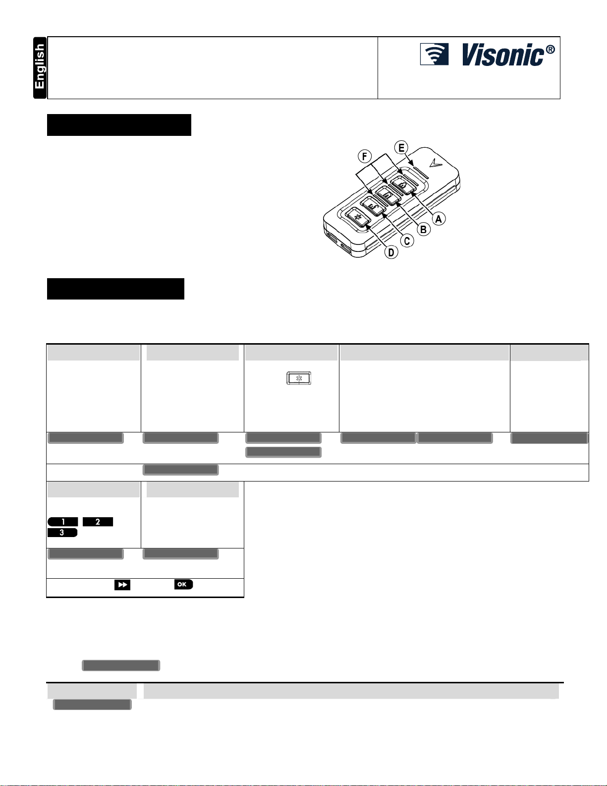
Figure 1: External View
A. ARM "AWAY" /
ARM "LATCHKEY"
B. ARM "HOME"
C. DISARM
D. AUX
E. Transmission LED
F. Status LEDs
2. INSTALLATION
2.1 Enrollment
Refer to the PowerMaster panel's Installer Guide and follow the procedure under the "02:ZONES/DEVICES" option of the Installer Menu.
A general description of the procedure is provided in the following flow chart.
Step 1 Step 2 Step 3 Step 4 Step 5
Enter the Installer menu
and select
“02:ZONES/DEVICES”
Select "ADD NEW
DEVICE"
See Note 1
MODIFY DEVICES
Enroll the keyfob by
holding the
and release it as soon as
the yellow LED lights.
Alternatively, enter the
device ID (printed on the
back of the keyfob)
ENROLL NOW or ADD NEW DEVICES 02.ZONES/DEVICES
ENTR ID:XXX-XXXX
Step 6 Step 7
Assign partitions to the
keyfob by pressing the
, and
buttons on the
panel
F02:P1 P2 P3
means scroll and select
Notes:
1. If the keyfob is already enrolled, you can configure the keyfob parameter and assign partitions via the “Modify Devices” option – see Step 2.
2. PARTITIONS will appear only if PARTITIONING was previously enabled in the panel (for further details, see "Partitioning" in the PowerMaster
Installer Guide).
Select the "Device
Settings" option and refer
to section to configure the
keyfob parameter (AUX).
DEVICE SETTINGS
Select the desired Keyfob Number for the new
keyfob
button
ID No. 301-XXXX F02:Keyfob
Enter PARTITIONS.
See Note 2
F02:PARTITIONS
2.2 Configuring the Keyfob Parameters
Enter the menu and follow the configuration instructions for the KF-235 PG2 keyfob as described in the following table.
D-303486 KF-235 PG2 Installation Instructions 1
DEVICE SETTINGS
Option Configuration Instructions
AUX A
Here you select the function of the AUX button on the keyfob device.
Options: Arm instant (default); Not Used; Status, Stop Beeps, Skip exit delay, and PGM.
Not Used: No function assigned to the AUX button.
Control panel displays and announces* the system status.
Status:
Stop Beeps:
Pressing the AUX button will cause the control panel and other devices in the system (such as keyfobs,
Page 2
keypads, sirens etc.) to stop beeping (for example during exit or entry delays).
Skip exit delay: Pressing the AUX button will immediately stop the exit delay and cause the system to arm
instant.
PGM: Pressing the AUX button will activate the PGM output.
corresponding sections of the control panel’s Installer Guide (see “OUTPUTS” menu) and User Guide (see
“SCHEDULER ” menu).
The functions of the PGM output is configured at the
Arm instant: Pressing the AUX button while the exit delay is in progress will cause the system to arm “instant” - the
entry delay is canceled.
* Applicable only to control panels that support the voice option.
3. USING THE KEYFOB
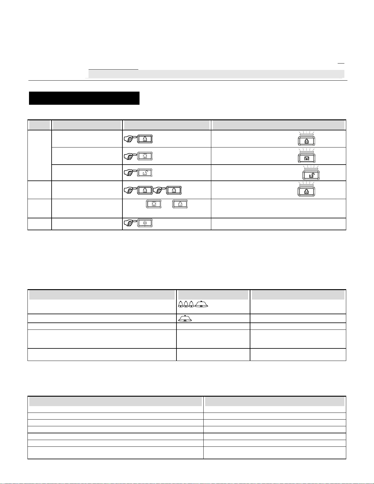
3.1 Keyfob Functionality
Step Functions User Actions ARM/DISARM LED Indication
1
2
3
4
Arm AWAY
Arm HOME
Disarm (OFF)
LATCHKEY
PANIC alarm
AUX
Press the
simultaneously ( 2 sec.)
and buttons
Blue LED above AWAY button lights
Blue LED above HOME button lights
Blue LED above DISARM button lights
Blue LED above AWAY button lights
-
According to the state of the alarm system, see section 2.2
3.2 Keyfob Response
When executing a command, the keyfob's Transmission LED blinks red once to indicate transmission of the command to the control panel. If
the operation is successfully completed, the green LED lights momentarily and a "happy tune" is heard. If the operation fails or cannot
be completed, for example, when the system is "not ready", the red LED lights steadily and a "sad tune" is heard. When executing a
command and there is a communication failure between the keyfob device and the control panel, the keyfob's Transmission LED remains off
and no tune is heard.
3.2.1 Primary LED and Buzzer Response to Keyfob Commands
Panel Response Buzzer Indication Transmission LED Indication
Success: Operation is successfully completed
Fail: Operation failed
No communication: For example, control panel is out of range.
Keyfob low battery:
Note: If transmission is still possible despite the battery condition,
the unit will send a low battery signal to the control panel.
Trouble in system:
When forced arming (bypass zones) is performed, the keyfob buzzer “protests” by emitting a continuous tone during the exit delay for 5
seconds (for more details, see the PowerMaster Installer Guide, section 5.5.2).
Happy (success) beep
None None
Depends on the operation that
is performed
Depends on the operation that
is performed
Sad (failure) beep
Momentary GREEN
Momentary RED
Blinks yellow 2 sec.
Lights yellow 2 sec.
3.2.2 Arming LED indication
When executing a command using the keyfob device, the status of the control panel is indicated by the status LEDs that light blue.
System State ARM/DISARM LED Indication
Exit from DISARM to AWAY AWAY lights
Exit from DISARM to HOME HOME lights
Entry from HOME
Entry from AWAY
Exit from HOME TO AWAY
Exit from AWAY TO HOME
Installer mode, Sync mode or when the system is otherwise reachable but
unavailable
2 D-303486 KF-235 PG2 Installation Instructions
DISARM blinks
DISARM blinks
AWAY lights
HOME lights
AWAY, HOME, DISARM blink twice, wait, then blink twice again
Page 3

4. MAINTENANCE
4.1 Replacing the Battery
A replacement 3V battery, CR-2032, is available from hardware and electrical supply stores. Replace the battery as shown in Figure 2.
Caution! Risk of explosion if battery is replaced by an incorrect type. Dispose of used batteries according to the manufacturer's instructions.
1. Remove backside screw and open the cover.
2. Using a non-metallic instrument such as a pencil, push out the
battery from its holder and install new battery (polarity "+" as
shown).
3. Put back the cover and re-attach it with the screw.
4. Test the unit by momentarily pressing one of the command
buttons (see Figure 1) – the LED should blink.
Figure 2: Battery Replacement
Caution!
Risk of explosion if battery is replaced by an incorrect type. Dispose of used battery according to manufacturer's instructions.
A. Button pad (make sure that it remains in its place).
B. LED light guides.
C. Battery holder.
D. Battery
4.2 Cleaning
Clean the keyfob only with a soft cloth or sponge moistened lightly with a mixture of water and mild detergent, and wipe it dry immediately.
The use of abrasives of any kind is strictly forbidden. Also never use solvents such as kerosene, acetone or thinner.
4.3 Periodic Test
Wireless equipment should be tested regularly to determine whether there are sources of interference and to protect against faults.
Refer to the PowerMaster Installer Guide, Chapter 6 Periodic Test, for instructions on how to conduct a periodic test.
5. TROUBLESHOOTING
Problem Diagnosis Proposed actions
Keyfob does not enroll
Keyfob LED does not light when
button is pressed
1. Keyfob was pre-enrolled 1. Enroll the keyfob again in the vicinity of the control panel.
2. The wrong ID number was entered 2. Reenter the ID number
3. No free location 3. If the maximum number of keyfobs has already been enrolled
4. Unknown device 4. Make sure the frequency used for the device is the same as the
Low battery condition
the alarm system will not allow enrolling any more keyfobs.
control panel frequency.
Replace the battery
6. PRODUCT LIMITATIONS
Visonic Ltd. wireless systems are very reliable and are tested to high standards. However, due to their low transmitting power and limited range
(required by FCC and other regulatory authorities), there are some limitations to be considered:
Control panels may be blocked by radio signals occurring on or near their operating frequencies, regardless of the code selected.
7. COMPLIANCE WITH STANDARDS
Compliance with Standards
FCC Compliance Statement
This device complies with Part 15 of the FCC Rules and with Industry Canada licence-exempt RSS standard(s).
Operation is subject to the following two conditions:
D-303486 KF-235 PG2 Installation Instructions 3
Europe: EN 300220, EN 50131-1 Grade 2, Class II and (EN 50134-2 Class II if used for social alarm), EN
301489, EN 50130-4, EN 60950, EN 50131-6
The KF-235 is compatible with the RTTE requirements - Directive 1999/5/EC of the European
Parliament and of the Council of 9 March 1999 and EN50131-1 Grade 2 Class II.
Certified by the Dutch testing and certificating body Telefication BV.
USA: CFR 47 part 15
Canada: RSS 210
Page 4

(1) This device may not cause harmful interference, and
(2) this device must accept any interference received, including interference that may cause undesired operation.
Le present appareil est conforme aux CNR d'Industrie Canada applicables aux appareils radio exempts de licence. L'exploitation est
autorisee aux deux conditions suivantes :(1) l'appareil ne doit pas produire de brouillage, et (2) l'utilisateur de l'appareil doit accepter tout
brouillage radioelectrique subi, meme si le brouillage est susceptible d'en compromettre le fonctionnement.
Note: This equipment has been tested and found to comply with the limits for a Class B digital device, pursuant to Part 15 of the FCC Rules.
These limits are designed to provide reasonable protection against harmful interference in a residential installation. This equipment generates,
uses and can radiate radio frequency energy and, if not installed and used in accordance with the instructions, may cause harmful interference
to radio communications. However, there is no guarantee that interference will not occur in a particular installation. If this equipment does
cause harmful interference to radio or television reception, which can be determined by turning the equipment off and on, the user is
encouraged to try to correct the interference by one or more of the following measures:
-- Reorient or relocate the receiving antenna.
-- Increase the separation between the equipment and receiver.
-- Connect the equipment into an outlet on a circuit different from that to which the receiver is connected.
-- Consult the dealer or an experienced radio/TV technician for help.
Warning!
Changes or modifications to this equipment not expressly approved by the party responsible for compliance (Visonic Ltd.) could void the user’s
authority to operate the equipment.
This equipment complies with FCC and IC RF radiation exposure limits set forth for an uncontrolled environment.
The technical documentation as required by the European Conformity Assessment procedure is kept at:
UNIT 6 MADINGLEY COURT CHIPPENHAM DRIVE KINGSTON MILTON KEYNES MK10 0BZ. TEL: (0845) 0755800 FAX: (0845) 0755801
W.E.E.E. Product Recycling Declaration
For information regarding the recycling of this product you must contact the company from which you orignially purchased it. If you are discarding this product and not
returning it for repair then you must ensure that it is returned as identified by your supplier. This product is not to be thrown away with everyday waste.
Directive 2002/96/EC Waste Electrical and Electronic Equipment.
APPENDIX: SPECIFICATIONS
Frequency Band (MHz) Europe and rest of world: 433-434, 868-869 USA: 912-919
Communication Protocol PowerG
Battery type 3V CR-2032 Lithium battery.
Low Battery Threshold 2.1 V
Battery Life Expectancy 8 years (for typical use)
Power Supply Type C
Operating Temperature 0° to 55°C (32° to 131°F)
Humidity Average relative humidity of approximate 75% non-condensing. For 30 days per year relative humidity
Dimensions (LxWxD) 60 x 34.5 x 12.5 mm (2-3/8 x 1-3/8 x 1/2 in.).
Weight (including battery) 25 g (0.9 oz).
WARRANTY
Visonic Limited (the “Manufacturer") warrants this product only (the "Product") to the
original purchaser only (the “Purchaser”) again st defective workmanship and materials
under normal use of the Product for a period of twelve (12) months from the date of
shipment by the Manufacturer.
This Warranty is absolutely conditional upon the Product having been properly installed,
maintained and operated under conditions of normal use in accordance with the
Manufacturers recommended installation and operation instructions. Products which
have become defective for any other reason, according to the Manufacturers discretion,
such as improper installation, failure to follow recommended installation and operational
instructions, neglect, willful damage, misuse or vandalism, accidental damage, alteration
or tampering, or repair by anyone other than the manufacturer, are not covered by this
Warranty.
The Manufacturer does not represent that this Product may not be compromised and/or
circumvented or that the Product will prevent any death and/or personal injury and/or
damage to property resulting from burglary, robbery, fire or otherwise, or that the
Product will in all cases provide adequate warning or protection. The Product, properly
installed and maintained, only reduces the risk of such events without warning and it is
not a guarantee or insurance that such events will not occur.
THIS WARRANTY IS EXCLUSIVE AND EXPRESSLY IN LIEU OF ALL OTHER
WARRANTIES, OBLIGATIONS OR LIABILITIES, WHETHER WRITTEN, ORAL,
EXPRESS OR IMPLIED, INCLUDING ANY WARRANTY OF MERCHANTABILITY OR
FITNESS FOR A PARTICULAR PURPOSE, OR OTHERWISE. IN NO CASE SHALL
THE MANUFACTURER BE LIABLE TO ANYONE FOR ANY CONSEQUENTIAL OR
INCIDENTAL DAMAGES FOR BREACH OF THIS WARRANTY OR ANY OTHER
WARRANTIES WHATSOEVER, AS AFORESAID.
THE MANUFACTURER SHALL IN NO EVENT BE LIABLE FOR ANY SPECIAL,
INDIRECT, INCIDENTAL, CONSEQUENTIAL OR PUNITIVE DAMAGES OR FOR
LOSS, DAMAGE, OR EXPENSE, INCLUDING LOSS OF USE, PROFITS, REVENUE,
OR GOODWILL, DIRECTLY OR INDIRECTLY ARISING FROM PURCHASER’S USE
OR INABILITY TO USE THE PRODUCT, OR FOR LOSS OR DESTRUCTION OF
OTHER PROPERTY OR FROM ANY OTHER CAUSE, EVEN IF MANUFACTURER
HAS BEEN ADVISED OF THE POSSIBILITY OF SUCH DAMAGE.
THE MANUFACTURER SHALL HAVE NO LIABILITY FOR ANY DEATH, PERSONAL
AND/OR BODILY INJURY AND/OR DAMAGE TO PROPERTY OR OTHER LOSS
WHETHER DIRECT, INDIRECT, INCIDENTAL, CONSEQUENTIAL OR OTHERWISE,
BASED ON A CLAIM THAT THE PRODUCT FAILED TO FUNCTION.
Note: If transmission is still possible despite the battery condition, the unit will send a low battery signal to
the control panel.
may vary between 85 % and 95 % non-condensing
However, if the Manufacturer is held liable, whether directly or indirectly, for any loss or
damage arising under this limited warranty, THE MANUFACTURER'S MAXIMUM
LIABILITY (IF ANY) SHALL NOT IN ANY CASE EXCEED THE PURCHASE PRICE OF
THE PRODUCT, which shall be fixed as liquidated damages and not as a penalty, and
shall be the complete and exclusive remedy against the Manufacturer.
When accepting the delivery of the Product, the Purchaser agrees to the said conditions
of sale and warranty and he recognizes having been informed of.
Some jurisdictions do not allow the exclusion or limitation of incidental or consequential
damages, so these limitations may not apply under certain circumstances.
The Manufacturer shall be under no liability whatsoever arising out of the corruption
and/or malfunctioning of any telecommunication or electronic equipment or any
programs.
The Manufacturers obligations under this Warranty are limited solely to repair and/or
replace at the Manufacturer’s discretion any Product or part thereof that may prove
defective. Any repair and/or replacement shall not extend the original Warranty period.
The Manufacturer shall not be responsible for dismantling and/or reinstallation costs. To
exercise this Warranty the Product must be returned to the Manufacturer freight pre-paid
and insured. All freight and insurance costs are the respon sibility of the Purchaser and
are not included in this Warranty.
This warranty shall not be modified, varied or extended, and the Manufacturer does not
authorize any person to act on its behalf in the modification, variation or extension of this
warranty. This warranty shall apply to the Product only. All products, accessories or
attachments of others used in conjunction with the Product, including batteries, shall be
covered solely by their own warranty, if any. The Manufacturer shall not be liable for any
damage or loss whatsoever, whether directly, indirectly, incidentally, consequentially or
otherwise, caused by the malfunction of the Product due to products, accessories, or
attachments of others, including batteries, used in conjunction with the Products. This
Warranty is exclusive to the original Purchaser and is not assignable.
This Warranty is in addition to and does not affect your legal rights. Any provision in this
warranty which is contrary to the Law in the state or country were the Product is supplied
shall not apply.
Warning! The user must follow the Manufacturer’s installation and operational
instructions including testing the Product and its whole system at least once a week and
to take all necessary precautions for his/her safety and the protection of his/her property.
01/08
VISONIC LTD. (ISRAEL): P.O.B 22020 TEL-AVIV 61220 ISRAEL. PHONE: (972-3) 645-6789, FAX: (972-3) 645-6788
VISONIC INC. (U.S.A.): 65 WEST DUDLEY TOWN ROAD, BLOOMFIELD CT. 06002-1376. PHONE: (860) 243-0833, (800) 223-0020.
FAX: (860) 242-8094
VISONIC LTD. (UK): UNIT 6 MADINGLEY COURT CHIPPENHAM DRIVE KINGSTON MILTON KEYNES MK10 0BZ. TEL: (0845) 0755800
FAX: (0845) 0755801. PRODUCT SUPPORT: (0845) 0755802
VISONIC GmbH (D-A-CH): KIRCHFELDSTR. 118, D-40215 DÜSSELDORF, TEL.: +49 (0)211 600696-0, FAX: +49 (0)211 600696-19
VISONIC IBERICA: ISLA DE PALMA, 32 NAVE 7, POLÍGONO INDUSTRIAL NORTE, 28700 SAN SEBASTIÁN DE LOS REYES, (MADRID), ESPAÑA.
TEL (34) 91659-3120, FAX (34) 91663-8468. www.visonic-iberica.es
INTERNET : www.visonic.com
VISONIC LTD. 2011 KF-235 PG2 D-303486 (Rev 0, 01/12)
4 D-303486 KF-235 PG2 Installation Instructions
 Loading...