

Page 1
K-980W
K-980W
K-980WK-980W
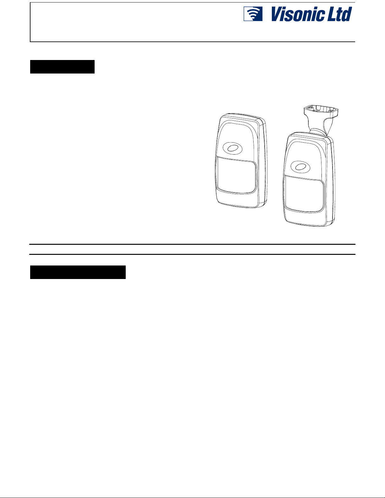
Pet-immune Wireless PIR Motion Detector
1. FEATURES
1. FEATURES
1. FEATURES1. FEATURES
• Uses TSI™ (Target Specific Imaging) technology for
distinction between humans and pets
• Immune to pets weighing up to 36 kg (80 l b)
• Integral swivel bracket for wall or ceiling installation
• Sealed chamber protects the optical system
• On-board CE and FCC approved transmitt er
• Programmable pulse counter (1, 2, 3 or 5 pulses)
• 9 Volt battery powered, with unique energy saving
circuitry
• Extremely-low current consum ption – 0.013 mA
• Automatically inhibited after detecting motion; rever ts to
the ready state if no moti on is detected for 2 minutes.
• A TEST/NORMAL selector eliminates t he 2-minute i nhibit
period and sets the pulse counter t o 1-pulse during walk
testing.
• Automatic transmission of lo w-battery and tamper alert s
• Three-position vertical adjustment
• White light protect ion
• Programmable 8-bit system code and 4-bit channel code
• Surface and corner mounting
Installation Instructions
• Rejects RF interference up to 1000 MHz
• Elegantly styled, sturdy case
• Keyhole-shaped slot for easy removal of PCB
Figure 1. The K-980W Wireless Detector
2. SPECIFICATIONS
2. SPECIFICATIONS
2. SPECIFICATIONS2. SPECIFICATIONS
OPTICAL
Max. Coverage Range: 9 x 9 m (30 x 30 ft) / 90
Pet Immunity: Immune to pets weighing up to 36 kg (80 lb)
under optimal environment al conditions.
Vertical Adjustment: 3-position adjustment scale: 1.8 m (6 ft),
2.1 m (7 ft) and 2.4 m (8 ft).
ELECTRICAL
Voltage: 9 Volt alkaline or lithium battery.
Standby Current: 0.013 mA.
LED: Walk Test & transmission.
Detector: Dual-element low-noise pyroelectric sensor.
Pulse Counter: Programmable to 1, 2, 3 or 5 pulses with wal k-t est
override.
Inhibit Timer: re-enables the unit about 2 minut es after alarm, if
no further motion is detected.
WIRELESS
Frequency (MHz): 315, 304, 404, 418, 433.92 or other
frequencies according to local r equirements.
Alarm Transmission Durati on: 2 seconds.
Encoding: 8-bit digital word, 256 combinations, pulse width
modulation.
Channels: 4 channels, s w itch selectable.
Battery Test: Automatic transmission of "Code 0" at 2-minute
intervals if the battery voltage drops below 7 V.
°
Tamper Alert: Transmis sion of the "Channel 2" code at 2-minut e
intervals, until the tamper swit ch is restored.
ENVIRONMENTAL
Operating Temperature: -10°C to 50°C (14°F to 122°F).
Storage Temperature: -20° to 60°C (-4°F to 140°F).
RFI Protection: Great er than 30 V/m up to 1000 MHz.
Note: The temperature range may be reduced due to battery
characteristics.
Compliance with Standards: Meets FCC Part 15 requirements;
The 433.92 MHz version complies with the European Council
Directive EMC 89/336/EEC & 92/ 31/EEC, and bears the CE mar k
and certific ation.
MOUNTING
Height: 1.8 to 2.4 m (6 to 8 ft)
Installation Options: Surface or corner (without bracket);
surface or ceiling (with bracket).
Bracket Adjustment: 20
applications) , 20
PHYSICAL
Dimensions (H x W x D): 117 x 65 x 47 mm.
(4-5/8 x 2-9/16 x 1-7/8 in.).
Weight: 92 g (3.25 oz) without bracket, 107 g (3.8 oz) with bracket.
Color: White
° left and right.
° downward (only in non-pet immune
DE3582 1
Page 2
3. INSTALLATION
t
3. INSTALLATION
3. INSTALLATION3. INSTALLATION
3.1 Installation Hints
Important! Under optimal environmental
conditions, t he detector is i mmune to animals
weighing up to 36 kg (80 lb) that move on the
floor or climb on furniture, as long as this
activity takes place bel ow 1 m (3 ft). Above 1
m (3 ft), the detector is immune topets
will decrease as the pet gets closer to the detector. It is
therefore recommended to select a mounting location tha
minimizes potential close proximity of animals.
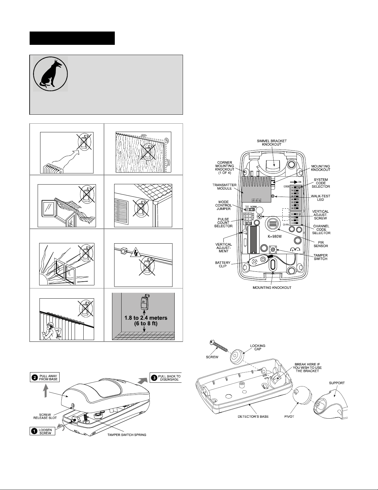
When installing keep in mind the advice given in Figure 2 below:
Do not aim at heat sources
Do not expose to air drafts Do not install outdoors
weighing 18 kg (40 lb), but the pet immunity
Mount on solid, stable surfaces
and remove it via the “keyhole” (see Figure 4).
3rd. Pull the PCB straight out and put it aside until required again.
4th. Refer to Figure 4 and punch out t he mounting knockouts at
the rear wall of the bas e (for surface mounting) or mounting
knockouts at the angled sides of the base (for corner
mounting).
5th. Hold the base against the wall at the selected installation
location and mark t he points for drilling.
6th. Drill the holes and insert the plastic anchors supplied (if
necessary).
7th. Return the PCB to its pl ace: al ign the ” keyhole” with t he head
of the vertical adjustment s crew, press the PCB against the
base, slide the PCB up and adjust it as explained in Para. 3.8.
Prevent direct s unlight from
reaching the detector
Do not install behind partitions
Figure 2. Installation Hints
Keep wiring away from
electrical power cables
3.2 Mounting without S wivel Br acket
1st. Remove the front cover as shown in Figure 3.
Figure 4. Inside View
3.3 Mounting with Sw ivel Bracket
1st. Remove the front cover as shown in Figure 3.
2nd. Remove the PCB and put it temporarily aside.
3rd. Punch out the large knoc kout in the round bulge at the top
part of the base (see Figure 5)
Figure 5. Attaching the Bracket
Figure 3. Cover Removal
2nd. Loosen the vertical adjustment screw, slide the PCB down
4th. Assemble the brack et as shown in Figure 5.
5th. Rotate the bracket t o the desired posit ion (see Figure 6) but
do not yet tighten the screw fully.
2 DE3582
Page 3

Figure 6. Wall and Ceiling Positions of Bracket
6th. Press the brack et agains t the mount ing sur fac e and mark t he
points for drilling. Drill out the holes and insert plastic
anchors.
7th. Attach the bracket to the mounting surface using the two
screws supplied.
H. Swivel the detector horizontall y to face the desired direct ion,
but do not tilt it if this is a pet immune application.
However, if pets are not present it is advisable to tilt the
detector as much as 20
possibilities.
° down. Figure 7 shows the t ilt/swivel
This feature is very useful for zoning
purposes - activation of different type of
zones at the control panel.
The channel selector consists of a 4-k ey
DIP switch (see Figure 9). The channel
code is selected by setting the key with
the desired channel number to ON.
If there is a low bat tery condition, a LOW
BATTERY alert code (code "0") will be
automatically
minutes, regardless of the channel selector setting. Code "0"
causes receivers equipped with a buzzer output to activate the
buzzer. Setting the 4 channel keys to OFF and initiating a
transmissi on is a way to check whether code "0" works.
Upon activation of the det ector’s t amper switch (by r emoving the
front cover), channel "2" code will be automatically transmitted
once every 2 minutes, r egardless of the c hannel selector setting.
Caution: Do not select channel 2 as the normal alarm channel,
because this will cause alarm and tamper events to have the
same channel code.
transmitted once every 2
Figure 9. Channel
Code Selector
3.7 Setting the Pulse Count er
The location of the puls e count selector i s indicated in Figur e 5.
Refer to Figure 10 below and mount the jumper as desired.
Figure 7. Tilt/Swivel Limits
I. Once the detector is directed as desired, tighten the bracket
assembly screw well, to prevent any further change of position.
3.4 Battery Installation
The K-980W is powered by a 9-volt alkaline or lithium battery.
Remove the detector's front cover, s nap the battery cl ip onto the
battery and place the battery i n its place ( below the pr inted c ir cuit
board). Before testing, allow 10 minutes for the detector to
stabilize (the LED may light during this time).
Warning! For proper operat ion, use only alkali ne or lithium ty pe
batteries.
3.5 System Code Selection
The code selector consists of an 8-key
DIP switch (see Figure 8). Each key is
set to either ON or OFF position to cr eate
a unique digital system code c ombinati on
(256 possibilities).
Select a digital code that matches the
one selected on the compani on receiver.
All wireless detectors and the receiver
used in the alarm system m ust be set
to the same digital system code.
CAUTION: The code combination 2, 4, 5, 6, 7 ON / 1, 3, 8 OFF
is a factory setti ng that must be avoi ded. Als o av oid c odes s uch
as all keys ON, all keys OFF or alternating ON-OFF settings.
Figure 8. System
Code Selector
Figure 10. Pulse Counter Setting Options
3.8 Vertical Adjustment
A. Pet-Immune Applications
To maintain maximum coverage range and
pet immunity, the vertical adjustment scale
must be adjusted in accordance with the
actual mounting height (refer to Figure 11).
Loosen the vertical adjustment screw and
slide th e printed circuit board up or down until
the pointer shows the actual mounting height on the scale.
When done, re-tighten the scr ew well.
3.6 Channel Code Selection
The Visonic Ltd. wir eless security s ystems have a multi- channel
capability. Each wireless K-980W detector can be set to t ransmit
one of 4 different c hannel codes. Each channel code ac tivates a
particular output circuit of the companion receiver.
Figure 11. Vertical Adjustment
DE3582 3
Page 4

B. Pet-Free Locations
To obtain the best cover age possible wher e no pets ar e present,
mount the detector with the integral bracket at any desir ed height
between 1.8 m (6 ft) and 2.4 m (8 ft). Then set the vertical
adjustment scal e to the 2.4 m (8 ft) position and tilt the detector
20
° down.
3.9 Setting the TST/NORM Jumper
Since battery saving is of utmost i mportanc e in normal use of the
detector unit, an automatic timer inhibits the detector for
approximately 2 minutes after each transmission. During this
period, the transmit ter cannot be triggered again by subs equent
motion within the protected area. The detector is automatically
rearmed 2 minutes after the last motion was detected.
For rapid walk tes ti ng of t he c overage pat ter n, you must el imi nat e
the 2 minute inhibit interval between successive alarms. The
NORM/TEST selector, when set to TEST, overrides the 2- minute
rearm timer, and also sets the pulse counter to 1 PULSE.
Remember that in the TEST mode, tamper and l ow batter y
will be transmitted at 1/2 second intervals instead of the usual 2minute intervals. When the s elector i s reset to NORM, the r earm
timer reverts to normal operation.
TEST Position Setting the jumper as shown
overrides the rear m timer and the pul se c ounter,
allowing you to walk test the detector rapidly.
NORMAL Position: Setting the jumper as
shown re-enables the 2-mi nute rear m t imer and
the pulse counter.
alerts
protective beam. All ow the unit to re-stabilize for 5 seconds
after each test.
F. In pet immune applicati ons, continue the test by sending the
house pet into the protected area. Make sure it does not
trigger the detec tor by moving across the protected area and
by climbing on furni ture within that ar ea.
G. Remove the cover and set the pulse counter as required for
the particular application.
H. Set the NORMAL/TEST selector to NORM, mount t he cover
and wait 5 minutes outside the cover age area. Then re-enter
the coverage area and verify that the LED li ght s ( r espons e wi ll
be immediate only if the pul se counter is s et to 1 pulse).
If you continue moving within the detector 's field of view, the
LED will turn OFF and the unit will remain disabled as long as
movement continues, due to the 2-minute battery saving
rearm timer. The unit will be rearmed provided that no motion
is detected for approximately 2 minutes, and will again be
ready to detect and signal.
CAUTION: The range and coverage area of the uni t should
be checked at least once a year. To assure proper
continuous function, the end user should be instructed to
perform a walk test at t he far end of the area to assure an
alarm signal prior to each time the alarm system is armed.
3.10 Final Testing
A. Snap the battery cl ip onto the 9 Volt alkali ne or lit hium battery
and allow ten minutes for the unit to stabilize before testing.
B. Adjust the vertical calibration position per Para. 3.8.
C. Set the Normal/Test selector to TEST.
D. Put the cover back in place.
E. W alk-test the entire pr otected area by walking slowly ac ross
it, observing the LED. The LED lights whenever you cross a
4. WARNINGS
4. WARNINGS
4. WARNINGS4. WARNINGS
Visonic Ltd. wir eless systems are very reliable and are tested to
high standards. However, due to their low transmitting power
(required by FCC and other regulatory authorities), there are
some limitations to be considered:
A. Receivers may be blocked by radi o signals on or near their
operating frequenci es, regardless of the code selected.
B. Receivers
a time.
C. Wir eles s equipment s hould be t est ed r egular ly ( at leas t once a
week) to determine if there are s ources of int erference and t o
protect against faults.
WARNING! Changes or modifications to this unit not ex pressly
approved by the party r espons i ble f or complianc e c ould v oi d t he
user's authority to operate the equi pment
can only respond to one transmitted r adio signal at
Class B digital device, pursuant to Part 15 of the FCC Rules. Thes e
limits are designed t o provide reasonable protection against harmful
interference in residential installations. This equipment generates,
uses and can radiate radio frequency energy and, if not instal led and
used in accordance with the instructions, may cause harmful
interference to radio and televis ion reception. However, there is no
guarantee that interference will not occur in a particular ins tallation. I f
this device does cause such int erference, which can be verified by
turning the device off and on, the user is enc ouraged to elim inate t he
interference by one or more of the following measures:
– Re-orient or re-locate the receiving antenna.
– Increase the distance between the device and t he receiver.
– Connect the device to an outlet on a c ircuit different from the one
which supplies power to the receiver.
– Consult the dealer or an experienced radio/TV technician.
This device has been tested and f ound to com ply with the lim its for a
WARRANTY
WARRANTY
WARRANTYWARRANTY
Visonic Ltd. and/or its subsidiaries and its affiliates ("the Manufacturer") warrants its
products hereinafter referred to as "the Product" or "Products" to be in conformance with
its own plans and specifications and to be free of defects in materials and workmanship
under normal use and service for a period of twelve months from the date of shipment by
the Manufacturer. The Manufacturer's obligations shall be limited within the warranty
period, at its option, to repair or replace the product or any part thereof. The Manufacturer
shall not be responsible for dismantling and/or reinstallation charges. To exercise the
warranty the product must be returned to the Manufacturer freight prepaid and insured.
This warranty does not apply in the following cases: improper installation, misuse,
failure to follow installation and operating instructions, alteration, abuse, accident or
tampering, and repair by anyone other than the Manufacturer.
This warranty is exclusive and expressly in lieu of all other warranties, obligations or
liabilities, whether written, oral, express or implied, including any warranty of
The Manufacturer does not represent that its Product may not be compromised and/or
circumvented, or that the Product will prevent any death, personal and/or bodily injury
and/or damage to property resulting from burglary, robbery, fire or otherwise, or that the
Product will in all cases provide adequate warning or protection. User understands that a
properly installed and maintained alarm may only reduce the risk of events such as
burglary, robbery, and fire without warning, but it is not insurance or a guarantee that such
will not occur or that there will be no death, personal damage and/or damage to property
as a result.
The Manufacturer shall have no liability for any death, personal and/or bodily injury
and/or damage to property or other loss whether direct, indirect, incidental,
consequential or otherwise, based on a claim that the Product failed to function.
However, if the Manufacturer is held liable, whether directly or indirectly, for any loss or
damage arising under this limited warranty or otherwise, regardless of cause or origin, the
Manufacturer's maximum liability shall not in any case exceed the purchase price of the
4 DE3582
Page 5

merchantability or fitness for a particular purpose, or otherwise. In no case shall the
Manufacturer be liable to anyone for any consequential or incidental damages for breach
of this warranty or any other warranties whatsoever, as aforesaid.
This warranty shall not be modified, varied or extended, and the Manufacturer does not
authorize any person to act on its behalf in the modification, variation or extension of this
warranty. This warranty shall apply to the Product only. All products, accessories or
attachments of others used in conjunction with the Product, including batteries, shall be
covered solely by their own warranty, if any. The Manufacturer shall not be liable for any
damage or loss whatsoever, whether directly, indirectly, incidentally, consequentially or
otherwise, caused by the malfunction of the Product due to products, accessories, or
attachments of others, including batteries, used in conjunction with the Products.
Product, which shall be fixed as liquidated damages and not as a penalty, and shall be the
complete and exclusive remedy against the Manufacturer.
Warning: The user should follow the installation and operation instructions and among
other things test the Product and the whole system at least once a week. For various
reasons, including, but not limited to, changes in environmental conditions, electric or
electronic disruptions and tampering, the Product may not perform as expected. The user
is advised to take all necessary precautions for his/her safety and the protection of his/her
property.
6/91
VISONIC LTD. (ISRAEL): P.O.B 22020 TEL-AVIV 61220 ISRAEL. PHONE: (972-3) 645-6789, FAX: (972-3) 645-6788
VISONIC INC. (U.S.A.): 10 NORTHWOOD DRIVE, BLOOMFIELD CT. 06002-1911. PHONE: (860) 243-0833, (800) 223-0020 FAX: (860) 242-8094
VISONIC LTD. (UK): UNIT 1, STRATTON PARK, DUNTON LANE, BIGGLESWADE, BEDS. SG18 8QS. PHONE: (01767) 600857 FAX: (01767) 601098
Internet Web Site: www.visonic.com
VISONIC LTD. 1999 K-980W DE3582- (REV. 1, 10/99)
D3582 5
 Loading...