

Page 1

DE1270 1
.
Advanced Pet-Immune PIR Motion Detector
Installation Instructions
)($785(6
x
Uses TSI™ (Target Specific Imaging) technology for
distinction between humans and pets
x
Immunity to pets weighing up to 36 kg (80 lb)
x
Integral swivel bracket for wall or ceiling installation
x
Sealed chamber protect s the optical system
x
Programmable pulse counter (1, 2 or 3 pulses)
x
Three-position vertical adjustment s cale
x
Low current consumption
x
Temperature compensation
x
Terminal for connecting an E.O.L. resist or
x
White light protection
x
Elegantly styled, sturdy case
x
Keyhole-shaped slot for easy removal of PCB
Figure 1. The K-980 Detector
63(&,),&$7,216
OPTICAL
Max. Coverage Range: 12 x 12 m (40 x 40 ft) / 90
Pet Immunity: Immune to pets weighing up to 36 kg (80 lb)
Vertical Adjustment: 3-pos ition adjustment scale: 1.8 m (6 ft),
2.1 m (7 ft) and 2.4 m (8 ft).
ELECTRICAL
Input Voltage: 9 to 16 VDC
Current @ 12 VDC: 10 mA standby, 18 mA on alarm (LED ON)
Alarm Relay: Normally closed (fail-safe) contacts with 18-ohm
resistor in s eries. Rating - 0.1 A resistive / 30 VDC.
Tamper Output: Normally closed contacts rated at 50 mA
resistive / 30 VDC.
Alarm Period: 2-3 seconds .
Pulse Counter: 3 position selector - 1, 2 or 3 pulse operation.
LED Control: Walk test enabled / disabled by internal link
Detector Type: Dual element l ow-noise pyroelectric sensor.
MOUNTING
Height: Up to 2.4 m (8 ft)
Installation Options: Surface or corner (without bracket);
surface or cei ling (with bracket).
Bracket Adjustment: 20 downward (only in non-pet immune
applications), 20 left and right.
ENVIRONMENTAL
RFI Protection: >30 V/m up to 1000 MHz.
Operating Temperatures: -10C to 50C (14F to 122F).
Storage Temperatures: -20C to 60C (-4F to 140F).
Compliance with Standards: This device complies with the
European Council Direct ive EMC 89/336/EEC & 92/31/EEC, and
bears the CE mark and certification.
PHYSICAL
Dimensions (H x W x D): 117 x 65 x 47 mm.
(4-5/8 x 2-9/16 x 1-7/8 in.) .
Weight: 98 g (3.4 oz) without bracket, 113 g (4 oz) with bracket.
,167$//$7,21
,QVWDOODWLRQ+LQWV
Important! The detector is immune to 36 kg
(80 lb) animals moving on the floor or
climbing on furniture as long as the activity
takes place below 1 m (3 ft) . Above the 1 m
(3 ft) height limit, the detec tor is immune to
18 kg (40 lb) pets, but the pet immunity will
decrease as the pet gets c loser to the detec tor. It is t herefore
recommended to select a mounting location that minimizes
potential close proximity of animals.
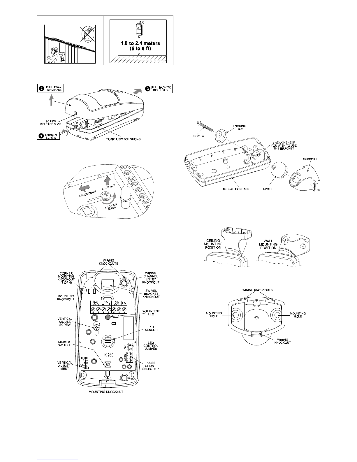
To minimize false alar ms, refer to Figure 2 below:
Do not aim at heat sources
Mount on solid, stable surfaces
Do not expose to air drafts Do not install outdoors
Prevent direct s unlight from
reaching the detector
Keep wiring away from
electrical power cables
Preliminar
y
Page 2
2 DE1270
Do not install behind partitions
0RXQWLQJZLWKRXW6ZL YHO%UDFNHW
A . Remove the front cover as shown in Figure 3.
Figure 3. Cover Removal
B . Loosen the vertical adjustment screw, slide the PCB down
and remove it via the “keyhole” (see Figure 4).
Figure 4. PCB Removal
C . Pull the PCB straight out and put it aside until r equired again.
D . Refer to Figure 5 and punch out the mounting knockouts at
the rear wall of the bas e (for surface mounting) or mounting
knockouts at the angled sides of the base (for corner
mounting).
Figure 5. Inside View
E . Punch out any one of the wiring knockouts s hown in Figure 5.
F . Hold the base against the wall at the selected installation
location and mark the points for drilling.
G . Drill the holes and insert the plastic anchors supplied (if
necessary).
H . Pass the wires through the wiring inlets into the base and
attach the base to the wall using the screws supplied.
I . Return the PCB to its place: ali gn the ”k eyhole” with t he head
of the vertical adjustment s crew, press the PCB against the
base, slide the PCB up and temporarily tighten the s crew.
J . Proceed to wire the terminal block as instructed in Para. 3.4.
0RXQWLQJZLWK6ZLYHO %UDFNHW
A . Remove the front cover as shown in Figure 3.
B . Remove the PCB (see Fi gure 4) and put it temporaril y aside.
C . Punch out the l arge knockout in the round bulge at the top
part of the base (s ee Figure 6)
Figure 6. Attaching the Bracket
D . Assemble the bracket as shown in Figure 6.
E . Rotate the bracket to t he desired position ( see Figure 7) but
do not yet tighten the screw fully.
Figure 7. Wall and Ceiling Positions of Bracket
F . Break the selected wiring knockouts in the bracket (Figure 8).
Figure 8. Bracket Base as Viewed from the Rear
G . Press the br acket agai nst the mount ing surf ace and mark the
points for drilling. Drill out the holes and insert plastic dowels.
H . Route the cable thr ough the bracket and int o the detector as
shown in Figure 9.
I . Attach the bracket to the mounting surface using the two
screws supplied.
Page 3

DE1270 3
Figure 9. Routing the Cable
J .
Swivel the detector hor izontally to face the des ired direction,
but
do not tilt it if this is a pet immune application
.
However, if pets are not present it is advisable to tilt the
detector as much as 20 down. Figure 10 shows the ti lt /s wivel
possibilities.
Figure 10. Tilt/Swivel Limits
K.
Having pointed the detector as desired, tighten the bracket
screw strongl y, to prevent any further change of position.
:LULQJ
The terminal block wiring shown in Figure 11 is self explanatory.
Note: The E.O.L. terminal is simply a connection point for an
E.O.L. resist or, if the circ uit requires one.
Figure 11. Terminal Block Wi ring
6HWWLQJWKH3XO V H&RXQWHU
The location of the puls e count selector i s indicated in Figur e 5.
Refer to Figure 12 below and mount the jumper as desired.
Figure 12. Pulse Counter Set ting Options
9HUWLFDO$GMXVW P HQW
A. Pet-Immune Applications
To maintain maximum coverage range and
pet immunity, the vertical adjustment scale
must be adjusted in accordance with the
actual mounting height (refer to Figure 13).
Loosen the vertical adjustment screw and
slide the printed circuit board up or down until
the pointer shows the actual mounting height on the scale.
When done, re- tighten the screw well .
Figure 13. Vertical Adjustment
B. Pet-Free Locations
To obtain the best coverage pos sible where no pets ar e present,
mount the detector with the integral bracket at any desir ed height
between 1.8 m (6 ft) and 2.4 m (8 ft). Then set the vertical
adjustment scal e
to the 2.4 m (8 ft) position
and tilt the detect or
20 down.
6HWWLQJWKH/(' &RQWURO-XPSHU
ON Position Setting the jumper as shown will
enable the LED, allowing you to walk test the
detector.
OFF Position: Setting the jumper as shown wi ll
disable the walk-t est LED.
:$/.7(67,1*
A . Set the pulse counter jumper, t he vertical angle adjustment
and the LED control jumper as ins tructed in Paragraphs 3.5,
3.6 and 3.7, respect ively.
B . Remount the cover back in place and fast en the cas e c losur e
screw.
C . Walk across the detector ’s field of view at vari ous distances
from the detector, and ver ify proper detection t hroughout the
detector's coverage area (the red LED will illuminate for
several seconds each time your motion is det ected).
Page 4

4 D1270
D .
In pet immune applications , continue the test by s ending the
house pet into the protected area. Make sure it does not
trigger the detect or by moving across the protected ar ea and
by climbing on furniture within that area.
Note: If the LED is disabled, y ou may use the control panel ’s
visual and audible indicators to verify proper function of the
detector.
Attention! To assure proper function of the detector, the r ange
and coverage area should be checked at least twice a year.
Furthermore, the user should be instructed to perform a walk
test at the far end of the coverage pattern to ass ure an alarm
signal prior to each time the alarm system is armed.
:$55$17<
:$55$17<
Visonic Ltd. and/or its subsidiaries and its affiliates ("the Manufacturer") warrants its
products hereinafter referred to as "the Product" or "Products" to be in conformance with
its own plans and specifications and to be free of defects in materials and workmanship
under normal use and service for a period of twelve months from the date of shipment by
the Manufacturer. The Manufacturer's obligations shall be limited within the warranty
period, at its option, to repair or replace the product or any part thereof. The Manufacturer
shall not be responsible for dismantling and/or reinstallation charges. To exercise the
warranty the product must be returned to the Manufacturer freight prepaid and insured.
This warranty does not apply in the following cases: improper installation, misuse,
failure to follow installation and operating instructions, alteration, abuse, accident or
tampering, and repair by anyone other than the Manufacturer.
This warranty is exclusive and expressly in lieu of all other warranties, obligations or
liabilities, whether written, oral, express or implied, including any warranty of
merchantability or fitness for a particular purpose, or otherwise. In no case shall the
Manufacturer be liable to anyone for any consequential or incidental damages for breach
of this warranty or any other warranties whatsoever, as aforesaid.
This warranty shall not be modified, varied or extended, and the Manufacturer does not
authorize any person to act on its behalf in the modification, variation or extension of this
warranty. This warranty shall apply to the Product only. All products, accessories or
attachments of others used in conjunction with the Product, including batteries, shall be
covered solely by their own warranty, if any. The Manufacturer shall not be liable for any
damage or loss whatsoever, whether directly, indirectly, incidentally, consequentially or
otherwise, caused by the malfunction of the Product due to products, accessories, or
attachments of others, including batteries, used in conjunction with the Products.
The Manufacturer does not represent that its Product may not be compromised and/or
circumvented, or that the Product will prevent any death, personal and/or bodily injury
and/or damage to property resulting from burglary, robbery, fire or otherwise, or that the
Product will in all cases provide adequate warning or protection. User understands that a
properly installed and maintained alarm may only reduce the risk of events such as
burglary, robbery, and fire without warning, but it is not insurance or a guarantee that such
will not occur or that there will be no death, personal damage and/or damage to property
as a result.
The Manufacturer shall have no liability for any death, personal and/or bodily injury
and/or damage to property or other loss whether direct, indirect, incidental,
consequential or otherwise, based on a claim that the Product failed to function.
However, if the Manufacturer is held liable, whether directly or indirectly, for any loss or
damage arising under this limited warranty or otherwise, regardless of cause or origin, the
Manufacturer's maximum liability shall not in any case exceed the purchase price of the
Product, which shall be fixed as liquidated damages and not as a penalty, and shall be the
complete and exclusive remedy against the Manufacturer.
Warning: The user should follow the installation and operation instructions and among
other things test the Product and the whole system at least once a week. For various
reasons, including, but not limited to, changes in environmental conditions, electric or
electronic disruptions and tampering, the Product may not perform as expected. The user
is advised to take all necessary precautions for his/her safety and the protection of his/her
property.
6/91
VISONIC LTD. (ISRAEL): P.O.B 22020 TEL-AVIV 61220 ISRAEL. PHONE: (972-3) 645-6789, FAX: (972-3) 645-6788
VISONIC INC. (U.S.A.): 10 NORTHWOOD DRIVE, BLOOMFIELD CT. 06002-1911. PHONE: (860) 243-0833, (800) 223-0020 FAX: (860) 242-8094
VISONIC LTD. (UK): UNIT 1, STRATTON PARK, DUNTON LANE, BIGGLESWADE, BEDS. SG18 8QS. PHONE: (01767) 600857 FAX: (01767) 601098
VISONIC LTD. 1998 K-980 DE1270- (REV. 0, 7/98)
 Loading...