

Page 1
DE1240 1
.
Temperature-Compensated Pet-Immune PIR Detector
Installation Instructions
,1752'8&7,21
The K-940 is an advanced pet immune PIR detector , that utilizes
TSI™ (Target Specif ic I maging) technol ogy, ens uring i mmunity t o
pets weighing up to 18 kg (40 lb).
The detector is also notable for its high stability, enhanced RFI
protection (great er than 30 V/m), high-temperat ure compens ation
for maximum "catch" performance and unique low-temperature
compensation for optim um false-alarm reject ion.
The pyroelectric sensor of the K-940 is enclosed in a sealed
chamber, protected from i ns ect s and air dr aft s . The pul s e count er
may be switched between 1 and 3 puls es, as desired.
Besides regular wall and corner mounting, 3 optional swivel
brackets are available for increased versatility of installation.
Figure 1. General View
63(&,),&$7,216
OPTICAL
Max. Coverage Range: 9 x 9 m (30 x 30 ft) / 90°.
Pet Immunity: Immune to animals wei ghing up to 18 kg (40 lb).
Vertical Adjustment: 3-position adjustment sc ale: 1.8 m (6 ft),
2.1 m (7 ft) and 2.4 m (8 ft).
ELECTRICAL
Voltage: 9 to 16 VDC.
Current: 17 mA at 12 VDC, 21 mA at 16 VDC
Alarm Output: Normally closed (fail-safe) contacts. 18 ohm
resistor in s eries with contact s. Rating - 0.1 A resi stive / 30 VDC.
Tamper Output: Normally closed, rated 0.5 A resistive / 30 VDC.
Alarm Period: 2-3 seconds .
Pulse Counter: 2 position selector, 1 or 3 pulse operation.
LED: Walk test enabled or disabled with internal link .
Detector: Dual-element low noise pyroelectric sensor.
MOUNTING
Surface or corner (without brackets).
Mounting Height: 1.8 m (6 ft) to 2.4 m (8 ft)
Optional Mounting Brackets (See Figure 3)
BR-1: Swivel Bracket, adjustable 30° down and 45° left, 45° right.
BR-2: Same as BR-1, with c orner adapter.
BR-3: Same as BR-1, with c eiling adapter.
ENVIRONMENTAL
Operating Temperature : -10°C to 50°C (14°F to 122°F).
Storage Temperature: -20°C to 60°C (-4°F to 140°F).
RFI Protection: >30 V/m t o 1000 MHz.
PHYSICAL
Size (H X W X D): 104 x 60 x 32 mm (4.1 x 2.4 x 1.3 in.).
Weight: 77 g (2-3/4 oz).
Color: White.
PATENTS
U.S. Patent No. Des. 346,567
,167$//$7,21
0RXQWLQJ
The K-940 can be surface mounted on a wall or in a corner.
Always mount the unit on a firm and stable s urface. For optional
swivel brackets, see Para. 3.2 and Figure 3.
A. Select the mounting location so that the expected motion of an
intruder would cross the detector’ s coverage pattern.
B. Mount the unit at the height of 1.8 m (6 ft) to 2.4 m (8 ft).
Important! The detect or is immune to 18 kg
(40 lb) animals moving on the floor or
climbing on furniture as long as the activity
takes place below 1 m (3 ft) . Above the 1 m
(3 ft) height limit, the detec tor is immune to
9 kg (20 lb) pets, but the pet immunity will
decrease as the pet gets c loser to the detec tor. It is t herefore
recommended to select a mounting location that minimizes
potential close proximity of animals.
C. It is advisable to avoid aiming the det ect or at heat ers , sour c es
of light or windows subjected to direct sunlight. Also avoid
running wiring close to high power electrical cables.
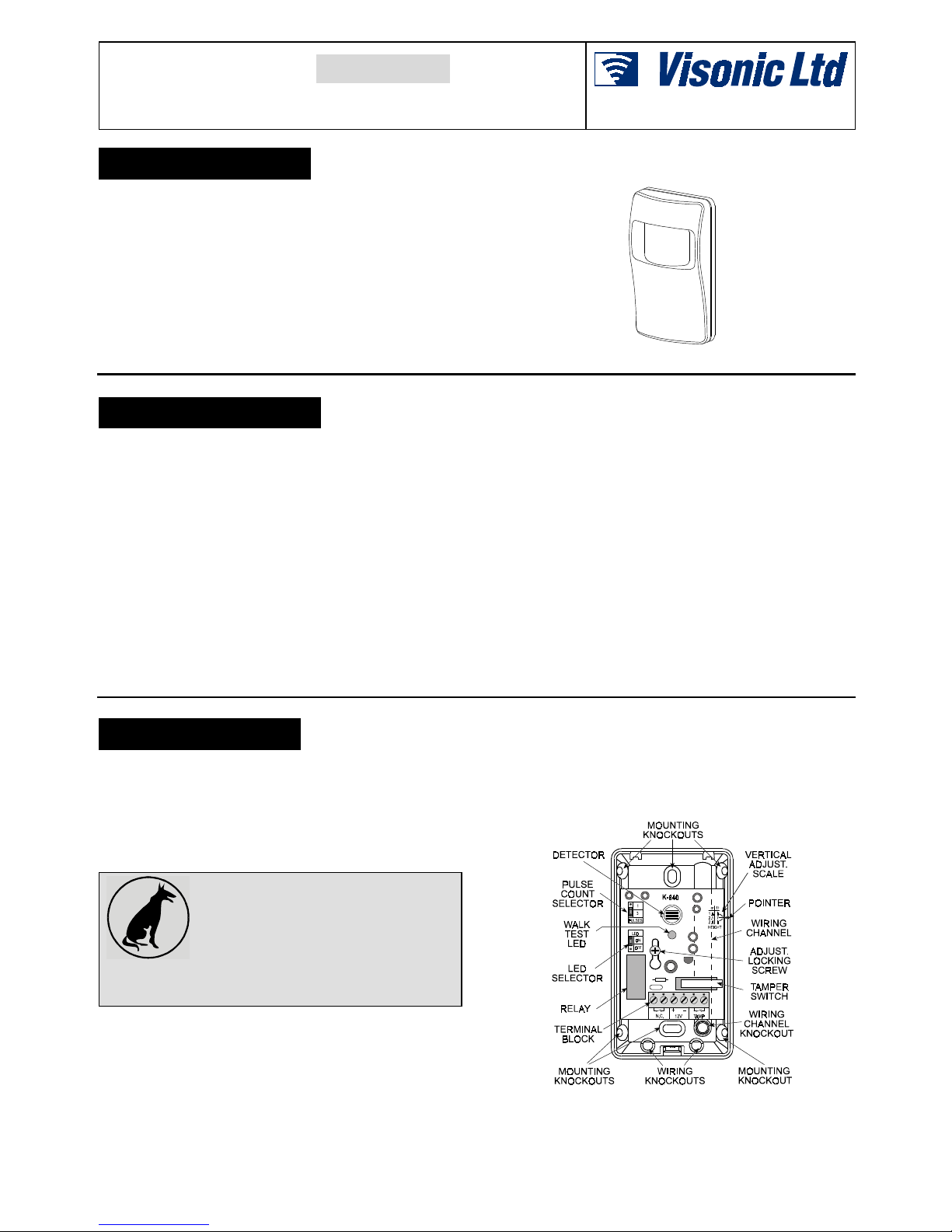
D. To remove the front cover, open the screw at the bottom of
the unit. Separate the front cover from the bas e. A keyhole
shaped slot permits easy r emoval of t he PCB f or mai ntenanc e
by just loosening the adjus tment locking screw.
E. For surface mounti ng use the two knockouts at the back of the
base; for corner mounting use the knockout s on the angled
sides. The unit must be fastened firmly to the mounting
surface, to avoid possible vibrations.
Figure 2. Components Layout
Preliminar
y
Page 2
2 DE1240
2SWLRQDO6ZLYHO%U DFNHWV
The BR-1 is a swivel, surface-mounted bracket which allows
greater flexibility when choosing the direc tion at which the K-940
is pointed. The BR-1 is adjus tabl e 30° downwar d and 45° le ft, 45°
right (see Figure 3).
The BR-2 is a swivel bracket kit for i nstal lati on in room c orner s. I t
consists of the BR-1 and a corner mounting adapter.
The BR-3 is a swivel bracket kit for installation on ceilings. It
consists of the BR- 1 and a ceiling mounting adapter.
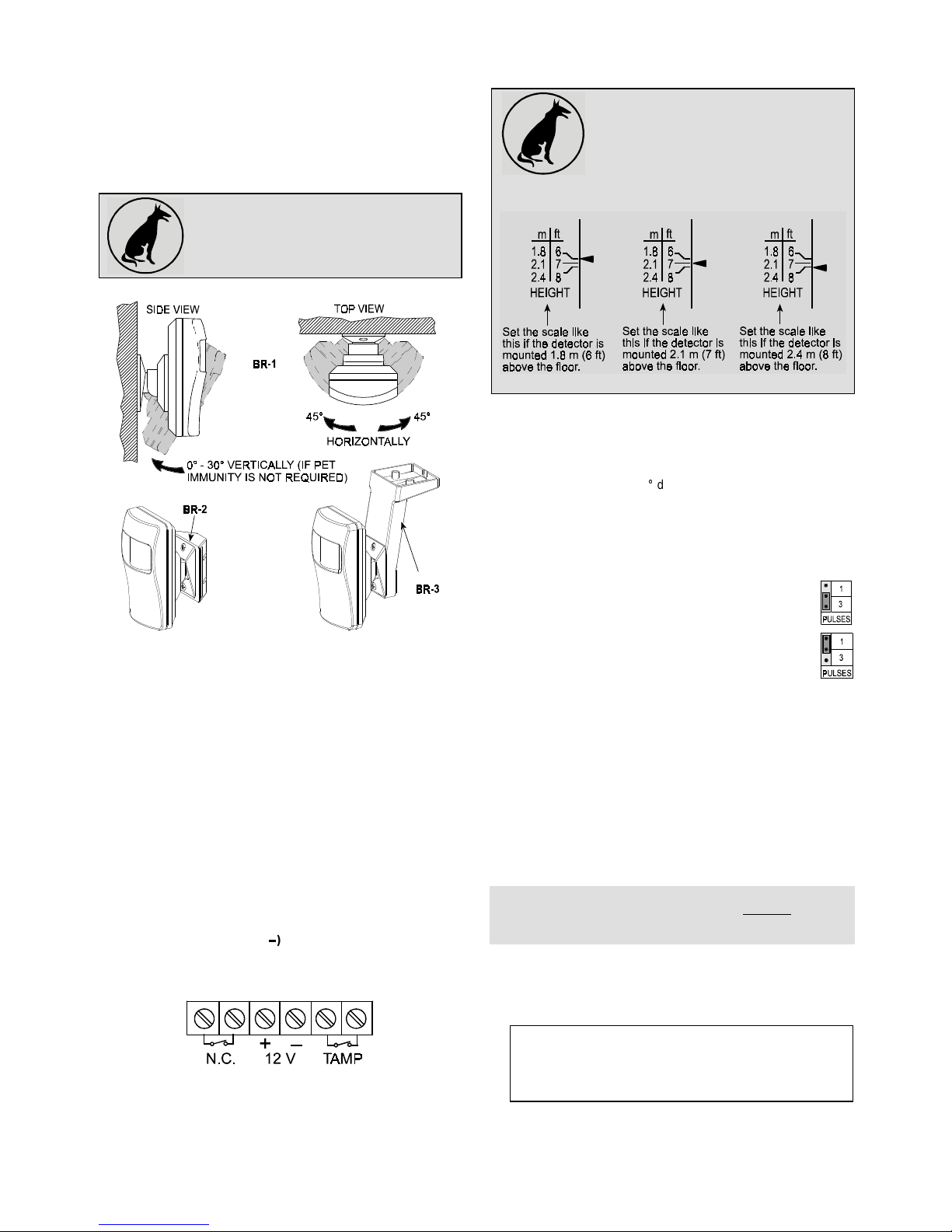
CAUTION! Tilting of the detector is not
allowed in pet immune applications. The
bracket should be used for horizontal
alignment only. The detector should be
kept vertical (perpendicular to the floor).
Figure 3. Optional Swivel Brackets
Having pointed the detector as des ired, tight en the brac ket sc rew
strongly, to prevent any further change of pos ition.
:LULQJ
To route the wires into the detector, use either the wiring
knockouts at the bottom of the base, or the channel and its
associated knock out on the back of the base ( see Figure 2). The
channel allows routing of wires from the ceiling under the detector
and then inside.
Connect wires to the t erminal block as fol lows (see Figure 4):
A. Connect the TAMP. N.C. terminals to a normally closed
24-hour protection zone of the control panel. The tamper
contact will open when the cover is removed.
B. Connect the N.C. relay terminals to a normal ly closed burgl ar
protection zone of the control panel. Relay contact s will open
when motion is detected or during power loss.
For installations in Canada, the N.C. relay must be
connected to an end-of-line resistor supervised zone.
C . Connect the 12V (+) and (±) terminals to a 9 to 16 Volt DC
power source and check for correct polarity. The power supply
must have at least 4 hours of battery back up. The detector' s
current drain is approximately 17 mA.
Figure 4. Terminal Block Wiring
9HUWLFDO$GMXVW P HQW
A. Pet-Immune Applications
To maintain maximum coverage range and
pet immunity, the vert ical adjustment scale
must be adjusted in accordance with the
actual mounting height (refer to Figure 5).
Loosen the vertical adjustment screw and
slide the printed circuit board up or down until
the pointer shows the actual mounting height on the scale.
When done, re- tighten the screw well.
Figure 5. Vertical Adjustment
B. Pet-Free Locations
To obtain the best coverage pos sible where no pets ar e present,
mount the detector wit h a swivel bracket (see Par a. 3.2) at any
desired height between 1.8 m (6 f t) and 2. 4 m ( 8 ft ). Then set t he
vertical adjustm ent s c ale
to the 2.4 m (8 ft) position
and use the
bracket to tilt the detector 30 down.
7KH3XOVH&RXQWHU
The K-940 is equipped with a programmabl e pulse counter that
can be set to count 1 or 3 pulses, before activating the alarm
relay. To set the pulse count er, place the jumper at the desir ed
setting (1 or 3).
3 Pulses: This setting provides improved protection
against false alarms caused by all types of environmental disturbances.
1 Pulse: This setti ng ac tual ly di s ables t he puls e c ounter .
It should be used in high s ec uri ty i ns tal lat ions , where t he
alarm must be activated on the first detected pulse.
:DON7HVWLQJ
A . Apply power and allow five minutes for the unit to warm up
and stabilize.
B . Adjust the vertical pattern angl e per Para. 3.4
C . Set the pulse counter per Para. 3.5.
D . Wal k-test the entire c overage area by walking slowly ac ross
the field of view (in opposite directions) and observing the
LED. The LED will light up whenever your motion is detect ed.
Allow 5 seconds between each test for the unit to stabilize.
Note: If the LED is disabled, you may use t he control panel ’s
visual and audible indi cators to verify pr oper function of the
detector.
E . I n pet immune applications, c ontinue the test by sending t he
pet into the protect ed area. Make sure it does not trigger the
detector by moving acr oss t he prot ec ted ar ea and by cl im bing
on furniture withi n that area.
F . After testing, the LED can be disabled to prevent
unauthorized persons f rom tracing the coverage pattern. To
disable the LED, remove the jumper from the upper and
middle pins of the LED selec tor (ON) and plac e it acr oss the
middle and lower pins (OFF) .
Note: The range and coverage area should be checked at
least once a year by the installer. To assure proper continuous
functioning, the user should be instructed to perform a walk
test at the far end of the cover age pattern t o assure an alarm
signal prior to each time the alarm system is arm e d .
Page 3

D1240 3
:$55$17<
:$55$17<
Visonic Ltd. and/or its subsidiaries and its affiliates ("the Manufacturer") warrants its
products hereinafter referred to as "the Product" or "Products" to be in conformance with
its own plans and specifications and to be free of defects in materials and workmanship
under normal use and service for a period of twelve months from the date of shipment by
the Manufacturer. The Manufacturer's obligations shall be limited within the warranty
period, at its option, to repair or replace the product or any part thereof. The Manufacturer
shall not be responsible for dismantling and/or reinstallation charges. To exercise the
warranty the product must be returned to the Manufacturer freight prepaid and insured.
This warranty does not apply in the following cases: improper installation, misuse,
failure to follow installation and operating instructions, alteration, abuse, accident or
tampering, and repair by anyone other than the Manufacturer.
This warranty is exclusive and expressly in lieu of all other warranties, obligations or
liabilities, whether written, oral, express or implied, including any warranty of
merchantability or fitness for a particular purpose, or otherwise. In no case shall the
Manufacturer be liable to anyone for any consequential or incidental damages for breach
of this warranty or any other warranties whatsoever, as aforesaid.
This warranty shall not be modified, varied or extended, and the Manufacturer does not
authorize any person to act on its behalf in the modification, variation or extension of this
warranty. This warranty shall apply to the Product only. All products, accessories or
attachments of others used in conjunction with the Product, including batteries, shall be
covered solely by their own warranty, if any. The Manufacturer shall not be liable for any
damage or loss whatsoever, whether directly, indirectly, incidentally, consequentially or
otherwise, caused by the malfunction of the Product due to products, accessories, or
attachments of others, including batteries, used in conjunction with the Products.
The Manufacturer does not represent that its Product may not be compromised and/or
circumvented, or that the Product will prevent any death, personal and/or bodily injury
and/or damage to property resulting from burglary, robbery, fire or otherwise, or that the
Product will in all cases provide adequate warning or protection. User understands that a
properly installed and maintained alarm may only reduce the risk of events such as
burglary, robbery, and fire without warning, but it is not insurance or a guarantee that such
will not occur or that there will be no death, personal damage and/or damage to property
as a result.
The Manufacturer shall have no liability for any death, personal and/or bodily injury
and/or damage to property or other loss whether direct, indirect, incidental,
consequential or otherwise, based on a claim that the Product failed to function.
However, if the Manufacturer is held liable, whether directly or indirectly, for any loss or
damage arising under this limited warranty or otherwise, regardless of cause or origin, the
Manufacturer's maximum liability shall not in any case exceed the purchase price of the
Product, which shall be fixed as liquidated damages and not as a penalty, and shall be the
complete and exclusive remedy against the Manufacturer.
Warning: The user should follow the installation and operation instructions and among
other things test the Product and the whole system at least once a week. For various
reasons, including, but not limited to, changes in environmental conditions, electric or
electronic disruptions and tampering, the Product may not perform as expected. The user
is advised to take all necessary precautions for his /her safety and the protection of
his/her property.
6/91
VISONIC LTD. (ISRAEL): P.O.B 22020 TEL-AVIV 61220 ISRAEL. PHONE: (972-3) 645-6789, FAX: (972-3) 645-6788
VISONIC INC. (U.S.A.): 10 NORTHWOOD DRIVE, BLOOMFIELD CT. 06002-1911. PHONE: (860) 243-0833, (800) 223-0020 FAX: (860) 242-8094
VISONIC LTD. (UK): UNIT 1, STRATTON PARK, DUNTON LANE, BIGGLESWADE, BEDS. SG18 8QS. PHONE: (01767) 600857 FAX: (01767) 601098
VISONIC LTD. 1998 K-940 DE1240-0 (REV. 0, 7/98)
 Loading...